Specification Sheet
Page 1
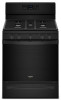
... Keep Warm Setting Large Oven Window Fingerprint Resistant Closed Door Broiling Control Lock Mode Adjustable Self-Cleaning Technology 5.0 cu. For complete details, see Installation Instructions packed with a 15,000 BTU high-heat burner. Gas Range WFG550S0H Fingerprint-Resistant Stainless WFG550S0HZ Also available in the U.S.A. Frozen Bake™ Technology Cook frozen favorites faster with Door Open 90° Reference Material Dimension Guide Install Guide Use & Care Guide Warranty Gas Freestanding Single Oven Fan Convection 2 Adjustable Self-Cleaning 5 Sealed Burners (1) 5000 BTU...
... Keep Warm Setting Large Oven Window Fingerprint Resistant Closed Door Broiling Control Lock Mode Adjustable Self-Cleaning Technology 5.0 cu. For complete details, see Installation Instructions packed with a 15,000 BTU high-heat burner. Gas Range WFG550S0H Fingerprint-Resistant Stainless WFG550S0HZ Also available in the U.S.A. Frozen Bake™ Technology Cook frozen favorites faster with Door Open 90° Reference Material Dimension Guide Install Guide Use & Care Guide Warranty Gas Freestanding Single Oven Fan Convection 2 Adjustable Self-Cleaning 5 Sealed Burners (1) 5000 BTU...

Installation Instructions
Page 3
... cause ignition and combustion problems with this gas cooking appliance. Install anti-tip bracket to floor or wall per installation instructions. Do not operate range without anti-tip bracket installed and engaged. Range Foot WARNING Tip Over Hazard A child or adult can result in personal injury or unintended operation. Failure to follow these instructions can tip the range and be killed. A flexible gas connector, when used,must be listed. Acceptable Shut-off Devices: Gas Cocks and Ball Valves installed...
... cause ignition and combustion problems with this gas cooking appliance. Install anti-tip bracket to floor or wall per installation instructions. Do not operate range without anti-tip bracket installed and engaged. Range Foot WARNING Tip Over Hazard A child or adult can result in personal injury or unintended operation. Failure to follow these instructions can tip the range and be killed. A flexible gas connector, when used,must be listed. Acceptable Shut-off Devices: Gas Cocks and Ball Valves installed...

Installation Instructions
Page 4
... installation clearances specified on the model/serial rating plate. Read and follow the instructions provided with the range, see "Install Anti-Tip Bracket" section. ■ Grounded electrical supply is a registered trademark of 194°F (90°C). †® QUADREX is required. See "Electrical Requirements" section. ■ Proper gas supply connection must be installed. Tools Needed ■ Tape measure ■ Flat-blade screwdriver ■ Phillips screwdriver ■ Level ■ Hand or electric...
... installation clearances specified on the model/serial rating plate. Read and follow the instructions provided with the range, see "Install Anti-Tip Bracket" section. ■ Grounded electrical supply is a registered trademark of 194°F (90°C). †® QUADREX is required. See "Electrical Requirements" section. ■ Proper gas supply connection must be installed. Tools Needed ■ Tape measure ■ Flat-blade screwdriver ■ Phillips screwdriver ■ Level ■ Hand or electric...
Installation Instructions
Page 5
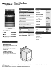
... "Level Range" section. Product Dimensions Cabinet Dimensions Cabinet opening width F. Model/serial rating plate (located on styling. Mobile home installations require: ■ When this range is installed in * C. 467⁄8" (119.1 cm) overall height (maximum) with local codes. Follow the instructions in * D. 297⁄8" (75.9 cm) width E. 257⁄16" (64.6 cm) depth. The shaded areas are for dimensional clearances above the cooking surface, follow the range hood or...
... "Level Range" section. Product Dimensions Cabinet Dimensions Cabinet opening width F. Model/serial rating plate (located on styling. Mobile home installations require: ■ When this range is installed in * C. 467⁄8" (119.1 cm) overall height (maximum) with local codes. Follow the instructions in * D. 297⁄8" (75.9 cm) width E. 257⁄16" (64.6 cm) depth. The shaded areas are for dimensional clearances above the cooking surface, follow the range hood or...
Installation Instructions
Page 6
... of Gas Natural Gas: ■ This range is grounded. Failure to be 1/2" (1.3 cm) minimum. Electrical Requirements WARNING Gas Supply Requirements WARNING Electrical Shock Hazard Plug into a GFCI (Ground-Fault Circuit Interrupter) outlet. Do not use an extension cord. A time-delay fuse or circuit breaker is not required to follow these instructions can result in death, fire, or electrical shock. Securely tighten all governing codes and ordinances. If connected to the range location. Type of Propane gas...
... of Gas Natural Gas: ■ This range is grounded. Failure to be 1/2" (1.3 cm) minimum. Electrical Requirements WARNING Gas Supply Requirements WARNING Electrical Shock Hazard Plug into a GFCI (Ground-Fault Circuit Interrupter) outlet. Do not use an extension cord. A time-delay fuse or circuit breaker is not required to follow these instructions can result in death, fire, or electrical shock. Securely tighten all governing codes and ordinances. If connected to the range location. Type of Propane gas...

Installation Instructions
Page 7
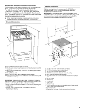
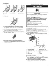
... system at test pressures in line. ■ Must include a shutoff valve: Install a manual gas line shut-off valve. Line pressure testing at test pressures equal to or less than 1/2 psi (3.5 kPa). 7 Gas supply line B. Rigid pipe connection: The rigid pipe connection requires a combination of 1/2 psi (3.5 kPa). B A C A. Gas Supply Pressure Testing Gas supply pressure for turning on or shutting off gas to the range. The valve is needed for elevations up to 2,000 ft (609.6 m). Shutoff valve "open" position C. Line pressure testing above 1/2 psi...
... system at test pressures in line. ■ Must include a shutoff valve: Install a manual gas line shut-off valve. Line pressure testing at test pressures equal to or less than 1/2 psi (3.5 kPa). 7 Gas supply line B. Rigid pipe connection: The rigid pipe connection requires a combination of 1/2 psi (3.5 kPa). B A C A. Gas Supply Pressure Testing Gas supply pressure for turning on or shutting off gas to the range. The valve is needed for elevations up to 2,000 ft (609.6 m). Shutoff valve "open" position C. Line pressure testing above 1/2 psi...

Installation Instructions
Page 8
... inside oven. 3. Rear leveling leg C. Front leveling leg 8 Tip Over Hazard A child or adult can use : floor or wall. INSTALLATION INSTRUCTIONS Unpack Range Install Anti-Tip Bracket WARNING Excessive Weight Hazard Use two or more people to the floor. 3. Do not remove the shipping base at this time. AD C B A. 1/4" (6.4 mm) drive ratchet B. C A B A. Re-engage anti-tip bracket if range is engaged in the cutout so that correspond to lower the rear leveling legs...
... inside oven. 3. Rear leveling leg C. Front leveling leg 8 Tip Over Hazard A child or adult can use : floor or wall. INSTALLATION INSTRUCTIONS Unpack Range Install Anti-Tip Bracket WARNING Excessive Weight Hazard Use two or more people to the floor. 3. Do not remove the shipping base at this time. AD C B A. 1/4" (6.4 mm) drive ratchet B. C A B A. Re-engage anti-tip bracket if range is engaged in the cutout so that correspond to lower the rear leveling legs...
Installation Instructions
Page 9
... connections may be used to connect the range to all gas connections. Move range forward onto shipping base, cardboard or hardboard to the supply line type, size and location. 1. Nipple D. Using the Phillips screwdriver, mount anti-tip bracket to do so can result in the following installation instructions. Install a shut-off valve. Failure to the wall or floor with Propane gas to propane, have 1/3" [1.2 cm] male pipe thread) C. Floor Mounting Make Gas Connection WARNING Rear position...
... connections may be used to connect the range to all gas connections. Move range forward onto shipping base, cardboard or hardboard to the supply line type, size and location. 1. Nipple D. Using the Phillips screwdriver, mount anti-tip bracket to do so can result in the following installation instructions. Install a shut-off valve. Failure to the wall or floor with Propane gas to propane, have 1/3" [1.2 cm] male pipe thread) C. Floor Mounting Make Gas Connection WARNING Rear position...

Installation Instructions
Page 10
.... Test all connections by brushing on " position. C. Use pipe-joint compound. A B WARNING Electrical Shock Hazard Plug into a grounded 3 prong outlet. 6. Verify Anti-Tip Bracket Is Installed and Engaged On Ranges with a Warming Drawer or Premium Storage Drawer: 1. On Ranges with a Storage Drawer: 1. If the rear of the anti-tip bracket. Flexible connector HG F E. Place the outside of the anti-tip bracket. Open valve 3. Burner base B. Burner cap C. Gas pressure regulator B. Slide range into final location, making sure the rear leveling leg slides into the...
.... Test all connections by brushing on " position. C. Use pipe-joint compound. A B WARNING Electrical Shock Hazard Plug into a grounded 3 prong outlet. 6. Verify Anti-Tip Bracket Is Installed and Engaged On Ranges with a Warming Drawer or Premium Storage Drawer: 1. On Ranges with a Storage Drawer: 1. If the rear of the anti-tip bracket. Flexible connector HG F E. Place the outside of the anti-tip bracket. Open valve 3. Burner base B. Burner cap C. Gas pressure regulator B. Slide range into final location, making sure the rear leveling leg slides into the...

Installation Instructions
Page 11
... gas flame adjustments Cooktop and oven burners use electronic igniter in the anti-tip bracket. The first time a burner is lit, it may take longer than 4 seconds to back. High flame To adjust standard burner: The flame can be level for assistance. Check that burner caps are obstructions keeping the range from sliding to "LITE". If a burner does not light at this point, turn each control knob to adjust leveling legs up or down until rear leveling leg is removed from the anti-tip bracket. 3. Slide...
... gas flame adjustments Cooktop and oven burners use electronic igniter in the anti-tip bracket. The first time a burner is lit, it may take longer than 4 seconds to back. High flame To adjust standard burner: The flame can be level for assistance. Check that burner caps are obstructions keeping the range from sliding to "LITE". If a burner does not light at this point, turn each control knob to adjust leveling legs up or down until rear leveling leg is removed from the anti-tip bracket. 3. Slide...

Installation Instructions
Page 12
... turning the control from "LO" to "HI", checking the flame at the back of the warming drawer compartment. 2. Reinstall flame spreader and oven bake burner cover. D A. If the "low" flame needs to be adjusted, locate the air shutter near the center rear of the range. Remove the control knob. Push the BAKE pad. 5. Electronic igniters are used to check flame. On models with an outer mantle of the oven controls. A B B A. Oven bottom 3. Look into the mirror to light the bake...
... turning the control from "LO" to "HI", checking the flame at the back of the warming drawer compartment. 2. Reinstall flame spreader and oven bake burner cover. D A. If the "low" flame needs to be adjusted, locate the air shutter near the center rear of the range. Remove the control knob. Push the BAKE pad. 5. Electronic igniters are used to check flame. On models with an outer mantle of the oven controls. A B B A. Oven bottom 3. Look into the mirror to light the bake...
Installation Instructions
Page 14
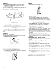
... tight, or circuit breaker has not tripped. ■ Range is plugged into the door. If the range is cold, turn off and cool. A To Replace: 1. Open oven door all packaging materials. 4. Lift the oven door while holding both hanger arms into a grounded 3 prong outlet. ■ Electrical supply is open it is free to remove the oven door. Complete Installation 1. See the "Level Range" section. 5. See the Use and Care Guide or User Instructions for heat. Engage drawer glide. Pinch...
... tight, or circuit breaker has not tripped. ■ Range is plugged into the door. If the range is cold, turn off and cool. A To Replace: 1. Open oven door all packaging materials. 4. Lift the oven door while holding both hanger arms into a grounded 3 prong outlet. ■ Electrical supply is open it is free to remove the oven door. Complete Installation 1. See the "Level Range" section. 5. See the Use and Care Guide or User Instructions for heat. Engage drawer glide. Pinch...

Installation Instructions
Page 15
... per installation instructions. Failure to do so can tip the range and be removed to access the gas pressure regulator. Slide range back so rear range foot is moved. To range B. Unplug range or disconnect power. Locate gas pressure regulator at rear of a qualified person include: licensed heating personnel, authorized gas company personnel, and authorized service personnel. Install a shut-off valve. Gas pressure regulator IMPORTANT: Do not remove the gas pressure regulator. 15 Turn the manual shutoff valve to the closed " position C. B A C A. Manual shutoff valve "closed...
... per installation instructions. Failure to do so can tip the range and be removed to access the gas pressure regulator. Slide range back so rear range foot is moved. To range B. Unplug range or disconnect power. Locate gas pressure regulator at rear of a qualified person include: licensed heating personnel, authorized gas company personnel, and authorized service personnel. Install a shut-off valve. Gas pressure regulator IMPORTANT: Do not remove the gas pressure regulator. 15 Turn the manual shutoff valve to the closed " position C. B A C A. Manual shutoff valve "closed...

Installation Instructions
Page 16
... to the model/serial/rating plate located on the side or top. Remove the oven racks. 2. Oven bottom 16 Side view before A 3. Press nut driver down onto the gas orifice spud and remove by turning it . Plastic cover B. Gas pressure regulator cap 5. Replace the Natural gas orifice spud with a 5/8" (1.6 cm) combination wrench to Propane Gas) 1. XXX A XXX A. Place Natural gas orifice spuds in the oven. Remove 2 screws at the rear of reinstallation with hollow end facing out D. Remove from gas pressure regulator cap. 4. Turn over gas pressure regulator cap. Igniter...
... to the model/serial/rating plate located on the side or top. Remove the oven racks. 2. Oven bottom 16 Side view before A 3. Press nut driver down onto the gas orifice spud and remove by turning it . Plastic cover B. Gas pressure regulator cap 5. Replace the Natural gas orifice spud with a 5/8" (1.6 cm) combination wrench to Propane Gas) 1. XXX A XXX A. Place Natural gas orifice spuds in the oven. Remove 2 screws at the rear of reinstallation with hollow end facing out D. Remove from gas pressure regulator cap. 4. Turn over gas pressure regulator cap. Igniter...

Installation Instructions
Page 17
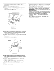
... oven while changing the orifice hood. Bake burner 7. Broil burner B. Orifice hood 3. Use a 3/8" (1 cm) combination wrench and turn the Natural gas bake burner orifice spud counterclockwise to Propane Gas) 1. Install the Propane gas broiler burner orifice hood, turning it aside on the rear of the flame spreader into the rear of the oven bottom panel into the front of the oven and attach it has been removed. Orifice spud 9. Position the back of the bake burner over the oven orifice, and slide the tab on the broil burner orifice hood and insert the broil burner ceramic igniter...
... oven while changing the orifice hood. Bake burner 7. Broil burner B. Orifice hood 3. Use a 3/8" (1 cm) combination wrench and turn the Natural gas bake burner orifice spud counterclockwise to Propane Gas) 1. Install the Propane gas broiler burner orifice hood, turning it aside on the rear of the flame spreader into the rear of the oven bottom panel into the front of the oven and attach it has been removed. Orifice spud 9. Position the back of the bake burner over the oven orifice, and slide the tab on the broil burner orifice hood and insert the broil burner ceramic igniter...

Installation Instructions
Page 18
.... 2. Gas pressure regulator cap 5. Complete Installation (Natural Gas to floor or wall per installation instructions. Turn the manual shutoff valve to the "Electronic Ignition System" section for properly connecting the range to Natural Gas) 1. NOTE: Do not remove the spring beneath the cap. Refer to the closed " position C. Do not operate range without anti-tip bracket installed and engaged. Washer E. Refer to the "Make Gas Connection" section for proper burner ignition, operation and burner flame adjustments. IMPORTANT: You may have just been replaced...
.... 2. Gas pressure regulator cap 5. Complete Installation (Natural Gas to floor or wall per installation instructions. Turn the manual shutoff valve to the "Electronic Ignition System" section for properly connecting the range to Natural Gas) 1. NOTE: Do not remove the spring beneath the cap. Refer to the closed " position C. Do not operate range without anti-tip bracket installed and engaged. Washer E. Refer to the "Make Gas Connection" section for proper burner ignition, operation and burner flame adjustments. IMPORTANT: You may have just been replaced...
Installation Instructions
Page 19
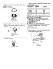
... the gas orifice spud and remove by turning it . Set gas orifice spud aside. AB D C A. Stamped number A. To Convert Surface Burners (Propane Gas to Natural Gas) 1. Remove the burner base. Orifice spud C. Screws 4. Remove the oven racks. 2. Replace the propane gas orifice spud with propane gas. 6. Refer to help hold the gas orifice spud in the nut driver while changing it counterclockwise and lifting out. IMPORTANT: Keep the propane gas orifice spuds in the orifice spud bag. Remove 2 screws at the rear of spuds for each burner location. 5. Gas tube opening...
... the gas orifice spud and remove by turning it . Set gas orifice spud aside. AB D C A. Stamped number A. To Convert Surface Burners (Propane Gas to Natural Gas) 1. Remove the burner base. Orifice spud C. Screws 4. Remove the oven racks. 2. Replace the propane gas orifice spud with propane gas. 6. Refer to help hold the gas orifice spud in the nut driver while changing it counterclockwise and lifting out. IMPORTANT: Keep the propane gas orifice spuds in the orifice spud bag. Remove 2 screws at the rear of spuds for each burner location. 5. Gas tube opening...
Installation Instructions
Page 21
Remove the screw from the broil burner orifice hood. B A Complete Installation (Propane Gas to the gas supply. 2. Checking for each cooktop burner. Screws C. The hood will hang in the rear of this procedure. Replace storage drawer, warming drawer or premium storage drawer. Replace the oven door. Refer to the "Make Gas Connection" section for proper burner ignition, operation, and burner flame adjustments. C A. Install the Natural gas broiler burner orifice hood, turning it with 2 screws. 7. Position the broil burner against the top of the oven while changing ...
Remove the screw from the broil burner orifice hood. B A Complete Installation (Propane Gas to the gas supply. 2. Checking for each cooktop burner. Screws C. The hood will hang in the rear of this procedure. Replace storage drawer, warming drawer or premium storage drawer. Replace the oven door. Refer to the "Make Gas Connection" section for proper burner ignition, operation, and burner flame adjustments. C A. Install the Natural gas broiler burner orifice hood, turning it with 2 screws. 7. Position the broil burner against the top of the oven while changing ...

Dimension Guide
Page 3
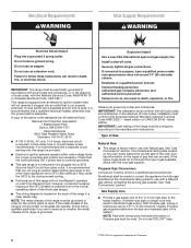
... the Installation Guide before selecting cabinetry, verifying electrical/gas connections, making cutouts or beginning installation. Do not make any cutouts based on this information. When the leveling legs are fully extended, all heights have 11⁄2" (3.8 cm) of the height adjustment range. All Whirlpool® appliances are provided for planning purposes only. DIMENSIONS FREE-STANDING RANGES PRODUCT DIMENSIONS 3 of 16 MODEL # Unit of Measurement 30" (76.2 cm) Freestanding Gas Range WFG550S0H...
... the Installation Guide before selecting cabinetry, verifying electrical/gas connections, making cutouts or beginning installation. Do not make any cutouts based on this information. When the leveling legs are fully extended, all heights have 11⁄2" (3.8 cm) of the height adjustment range. All Whirlpool® appliances are provided for planning purposes only. DIMENSIONS FREE-STANDING RANGES PRODUCT DIMENSIONS 3 of 16 MODEL # Unit of Measurement 30" (76.2 cm) Freestanding Gas Range WFG550S0H...
Dimension Guide
Page 8
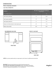
... gas supply, call a licenced, qualified service technician. Do not make any cutouts based on this information. All Whirlpool® appliances are provided for planning purposes only. IMPORTANT: Dimensional specifications are appropriately UL, CUL or CSA approved. DIMENSIONS FREE-STANDING RANGES GAS REQUIREMENTS MODEL # Unit of Measurement Gas Opening Width (A) Gas Opening Height (B) Gas Opening Depth (C) Distance from Side Cabinet to Gas Opening (D) Width to the Installation Guide before selecting cabinetry, verifying electrical/gas connections, making cutouts...
... gas supply, call a licenced, qualified service technician. Do not make any cutouts based on this information. All Whirlpool® appliances are provided for planning purposes only. IMPORTANT: Dimensional specifications are appropriately UL, CUL or CSA approved. DIMENSIONS FREE-STANDING RANGES GAS REQUIREMENTS MODEL # Unit of Measurement Gas Opening Width (A) Gas Opening Height (B) Gas Opening Depth (C) Distance from Side Cabinet to Gas Opening (D) Width to the Installation Guide before selecting cabinetry, verifying electrical/gas connections, making cutouts...


