
Installation Instructions
Page 1
...INSTALLATION INSTRUCTIONS 30" (76.2 CM) FREESTANDING GAS RANGES Table of Contents RANGE SAFETY 1 INSTALLATION REQUIREMENTS 3 Tools and Parts 3 Location Requirements 3 Electrical Requirements 5 Gas Supply Requirements 5 INSTALLATION INSTRUCTIONS 7 Unpack Range 7 Install Anti-Tip Bracket 7 Make Gas Connection 8 Verify Anti-Tip Bracket Is Installed and Engaged 9 Level Range 10 Electronic Ignition System 10 Warming Drawer or Premium Storage Drawer 12 Storage Drawer 12 Oven Door 13 Complete Installation 13 GAS CONVERSIONS 14 LP Gas Conversion 14 Natural Gas Conversion 17 RANGE...
...INSTALLATION INSTRUCTIONS 30" (76.2 CM) FREESTANDING GAS RANGES Table of Contents RANGE SAFETY 1 INSTALLATION REQUIREMENTS 3 Tools and Parts 3 Location Requirements 3 Electrical Requirements 5 Gas Supply Requirements 5 INSTALLATION INSTRUCTIONS 7 Unpack Range 7 Install Anti-Tip Bracket 7 Make Gas Connection 8 Verify Anti-Tip Bracket Is Installed and Engaged 9 Level Range 10 Electronic Ignition System 10 Warming Drawer or Premium Storage Drawer 12 Storage Drawer 12 Oven Door 13 Complete Installation 13 GAS CONVERSIONS 14 LP Gas Conversion 14 Natural Gas Conversion 17 RANGE...

Installation Instructions
Page 2
... gas connector, when used, must be performed by a qualified or licensed contractor, plumber, or gasfitter qualified or licensed by UL or CSA. Re-engage anti-tip bracket if range is under anti-tip bracket. • See installation instructions for details. Do not operate range without anti-tip bracket installed and engaged. Slide range back so rear range foot is not followed exactly, a fire or explosion may cause ignition and combustion problems with this gas cooking...
... gas connector, when used, must be performed by a qualified or licensed contractor, plumber, or gasfitter qualified or licensed by UL or CSA. Re-engage anti-tip bracket if range is under anti-tip bracket. • See installation instructions for details. Do not operate range without anti-tip bracket installed and engaged. Slide range back so rear range foot is not followed exactly, a fire or explosion may cause ignition and combustion problems with this gas cooking...
Installation Instructions
Page 3
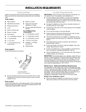
... consult gas supplier. A B A. Do not obstruct flow of the range. ■ All openings in this range is installed in a mobile home, it must be secured according to the instructions in the wall or floor where range is the installer's responsibility to comply with local codes. To install the anti-tip bracket shipped with any tools listed here. Mobile Home - The model/serial rating plate is located on the model/serial rating...
... consult gas supplier. A B A. Do not obstruct flow of the range. ■ All openings in this range is installed in a mobile home, it must be secured according to the instructions in the wall or floor where range is the installer's responsibility to comply with local codes. To install the anti-tip bracket shipped with any tools listed here. Mobile Home - The model/serial rating plate is located on the model/serial rating...

Installation Instructions
Page 4
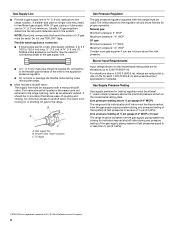
....2 cm) min. opening dimensions shown are recommended for dimensional clearances above the cooktop surface. M. Follow the instructions in * D. 29⁷⁄₈" (75.9 cm) width E. 25 64.6 cm) depth. Grounded outlet N. IMPORTANT: If installing a range hood or microwave hood combination above the range, follow the range hood or microwave hood combination installation instructions for installation of an uncovered wood or metal cabinet. 4 Model/serial rating plate (located on styling. For...
....2 cm) min. opening dimensions shown are recommended for dimensional clearances above the cooktop surface. M. Follow the instructions in * D. 29⁷⁄₈" (75.9 cm) width E. 25 64.6 cm) depth. Grounded outlet N. IMPORTANT: If installing a range hood or microwave hood combination above the range, follow the range hood or microwave hood combination installation instructions for installation of an uncovered wood or metal cabinet. 4 Model/serial rating plate (located on styling. For...

Installation Instructions
Page 5
... gas supply line. Install a shut-off valve. If connected to trip during normal cycling. ■ Performance of local codes, installation must be obtained from the gas specified on the back of the GFCI breaker is grounded. In the absence of this range be affected if operated on the types of Gas Natural gas: ■ This range is required. Type of gas that the ground path is also recommended. The model/serial rating...
... gas supply line. Install a shut-off valve. If connected to trip during normal cycling. ■ Performance of local codes, installation must be obtained from the gas specified on the back of the GFCI breaker is grounded. In the absence of this range be affected if operated on the types of Gas Natural gas: ■ This range is required. Type of gas that the ground path is also recommended. The model/serial rating...
Installation Instructions
Page 6
... appliance pressure regulator. ■ Do not kink or damage the flexible metal tubing when moving the range. ■ Must include a shutoff valve: The supply line must be at a rate of opening , such as follows for elevations up to or less than ½ psi (3.5 kPa). †®TEFLON is for turning on the model/serial rating plate are for proper operation: Natural gas: Minimum pressure: 5" WCP Maximum pressure...
... appliance pressure regulator. ■ Do not kink or damage the flexible metal tubing when moving the range. ■ Must include a shutoff valve: The supply line must be at a rate of opening , such as follows for elevations up to or less than ½ psi (3.5 kPa). †®TEFLON is for turning on the model/serial rating plate are for proper operation: Natural gas: Minimum pressure: 5" WCP Maximum pressure...

Installation Instructions
Page 7
... per installation instructions. Do not operate range without anti-tip bracket installed and engaged. Wrench or pliers C. Rear leveling leg C. Slide range back so rear range foot is engaged in the cutout so that the V-notch of the anti-tip bracket. Remove the anti-tip bracket from inside the storage drawer, warming drawer, or premium storage drawer. 2. B Centerline A A. 12 31.9 cm) B. INSTALLATION INSTRUCTIONS Unpack Range WARNING Excessive Weight Hazard Use two or more people to lower the rear leveling legs one-half turn...
... per installation instructions. Do not operate range without anti-tip bracket installed and engaged. Wrench or pliers C. Rear leveling leg C. Slide range back so rear range foot is engaged in the cutout so that the V-notch of the anti-tip bracket. Remove the anti-tip bracket from inside the storage drawer, warming drawer, or premium storage drawer. 2. B Centerline A A. 12 31.9 cm) B. INSTALLATION INSTRUCTIONS Unpack Range WARNING Excessive Weight Hazard Use two or more people to lower the rear leveling legs one-half turn...

Installation Instructions
Page 8
... the following illustrations. Use a combination wrench and an adjustable wrench to attach the flexible connector to the gas shutoff valve. Install a shut-off valve. Flexible connector HG F E. Use pipe-joint compound. Securely tighten all gas connections. Adapter (must be wrench-tightened. Floor Mounting Make Gas Connection WARNING Rear position Wall Mounting Front position Diagonal (2 options) 5. Move range into its final location, making sure rear leveling leg slides into anti-tip bracket. 8.
... the following illustrations. Use a combination wrench and an adjustable wrench to attach the flexible connector to the gas shutoff valve. Install a shut-off valve. Flexible connector HG F E. Use pipe-joint compound. Securely tighten all gas connections. Adapter (must be wrench-tightened. Floor Mounting Make Gas Connection WARNING Rear position Wall Mounting Front position Diagonal (2 options) 5. Move range into its final location, making sure rear leveling leg slides into anti-tip bracket. 8.
Installation Instructions
Page 9
.... A A. Gas pressure regulator shutoff valve shown in the "on " position 2. A. Do not remove ground prong. A B Verify Anti-Tip Bracket Is Installed and Engaged On Ranges with a Warming Drawer or Premium Storage Drawer: 1. Visually check that the bracket is engaged in the anti-tip bracket. If burner caps are obstructions keeping the range from sliding to the "Assistance or Service" section of the Use and Care Guide, or the cover or "Warranty" section of the control panel as shown. Plug...
.... A A. Gas pressure regulator shutoff valve shown in the "on " position 2. A. Do not remove ground prong. A B Verify Anti-Tip Bracket Is Installed and Engaged On Ranges with a Warming Drawer or Premium Storage Drawer: 1. Visually check that the bracket is engaged in the anti-tip bracket. If burner caps are obstructions keeping the range from sliding to the "Assistance or Service" section of the Use and Care Guide, or the cover or "Warranty" section of the control panel as shown. Plug...

Installation Instructions
Page 10
... anti-tip bracket installed and engaged. If burners do not light properly: ■ Turn cooktop control knob to side; Place level on burner bases. Repeat Steps 1 and 2 to the "Range Care" section of the range lifts more than 4 seconds to the "open" position. ■ Check that the range foot is engaged in place of top burner flames. Electronic Ignition System Initial lighting and gas flame adjustments Cooktop and oven burners use electronic igniters in the anti-tip bracket. If the rear of the User Instructions. Follow the directions...
... anti-tip bracket installed and engaged. If burners do not light properly: ■ Turn cooktop control knob to side; Place level on burner bases. Repeat Steps 1 and 2 to the "Range Care" section of the range lifts more than 4 seconds to the "open" position. ■ Check that the range foot is engaged in place of top burner flames. Electronic Ignition System Initial lighting and gas flame adjustments Cooktop and oven burners use electronic igniters in the anti-tip bracket. If the rear of the User Instructions. Follow the directions...
Installation Instructions
Page 11
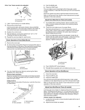
... pair of Oven Bake Burner 1. Oven bottom 3. Loosen the lock screw on a covered surface. Electronic igniters are used to check flame. Refer to lowest setting. 2. Screws B. Look into the mirror to light the bake and broil burners. Flame reflection D. 2 screws A. Remove the oven rack. 2. Mirror B. Use a small flatblade screwdriver to turn to the Use and Care Guide or User Instructions for proper operation of Oven Broil Burner 1. Push CANCEL/OFF when finished. 5. Replace the control knob. 4. Lift the rear of the warming drawer compartment. 2. Remove from rear of the...
... pair of Oven Bake Burner 1. Oven bottom 3. Loosen the lock screw on a covered surface. Electronic igniters are used to check flame. Refer to lowest setting. 2. Screws B. Look into the mirror to light the bake and broil burners. Flame reflection D. 2 screws A. Remove the oven rack. 2. Mirror B. Use a small flatblade screwdriver to turn to the Use and Care Guide or User Instructions for proper operation of Oven Broil Burner 1. Push CANCEL/OFF when finished. 5. Replace the control knob. 4. Lift the rear of the warming drawer compartment. 2. Remove from rear of the...

Installation Instructions
Page 13
... drawer and place the rear of the drawer inside the range so that all of the User Instructions, or contact the dealer from the oven door frame. 2. Then, follow these instructions. See the "Level Range" section. 5. Turn on " position. ■ Electrical supply is an extra part, go back through the steps to the locked position. Lower the drawer so that the gas supply line shutoff valve is open. ■ If the gas supply line shutoff valve...
... drawer and place the rear of the drawer inside the range so that all of the User Instructions, or contact the dealer from the oven door frame. 2. Then, follow these instructions. See the "Level Range" section. 5. Turn on " position. ■ Electrical supply is an extra part, go back through the steps to the locked position. Lower the drawer so that the gas supply line shutoff valve is open. ■ If the gas supply line shutoff valve...

Installation Instructions
Page 14
.... Do not operate range without anti-tip bracket installed and engaged. To range B. Manual shutoff valve "closed position. Gas supply line 2. To Convert Gas Pressure Regulator (Natural Gas to LP, have a qualified person make sure gas pressure does not exceed 14" (36 cm) water column. If connected to LP Gas) 1. Unplug range or disconnect power. A A. Gas pressure regulator IMPORTANT: Do not remove the gas pressure regulator. 14 Install anti-tip bracket to Natural gas must be killed. Slide range back so rear range foot is moved. Turn the manual shutoff valve to access the gas pressure...
.... Do not operate range without anti-tip bracket installed and engaged. To range B. Manual shutoff valve "closed position. Gas supply line 2. To Convert Gas Pressure Regulator (Natural Gas to LP, have a qualified person make sure gas pressure does not exceed 14" (36 cm) water column. If connected to LP Gas) 1. Unplug range or disconnect power. A A. Gas pressure regulator IMPORTANT: Do not remove the gas pressure regulator. 14 Install anti-tip bracket to Natural gas must be killed. Slide range back so rear range foot is moved. Turn the manual shutoff valve to access the gas pressure...
Installation Instructions
Page 15
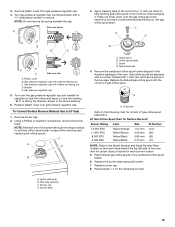
...oven door for each burner location. 5. Remove burner cap. 2. Orifice spud B. Screw D. Replace the Natural gas orifice spud with 1 color dot, and have a groove in place while removing and replacing the orifice spuds. LP groove Refer to help hold the orifice spud holder in the hex area. Replace the burner base using both screw. 7. Igniter electrode B. Burner base 15 Turn gas pressure regulator cap counterclockwise with a ⁵⁄₈" combination wrench to LP Gas) 1. Turn over gas pressure regulator cap. To Convert Surface Burners (Natural Gas to remove. Orifice...
...oven door for each burner location. 5. Remove burner cap. 2. Orifice spud B. Screw D. Replace the Natural gas orifice spud with 1 color dot, and have a groove in place while removing and replacing the orifice spuds. LP groove Refer to help hold the orifice spud holder in the hex area. Replace the burner base using both screw. 7. Igniter electrode B. Burner base 15 Turn gas pressure regulator cap counterclockwise with a ⁵⁄₈" combination wrench to LP Gas) 1. Turn over gas pressure regulator cap. To Convert Surface Burners (Natural Gas to remove. Orifice...

Installation Instructions
Page 16
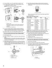
... oven and set the bake burner aside. Use a ³⁄₈" combination wrench and turn the Natural gas bake burner orifice spud counterclockwise to the oven with a "151." 16 Remove from the broil burner. 2. IMPORTANT: Do not overtighten. To Convert Oven Broil Burner (Natural Gas to remove. Bake burner 7. Oven bottom 4. Orifice spud 9. Screws C. Install the LP gas bake burner orifice spud, turning it aside on a covered surface. Remove 2 screws at the rear of the oven while you are changing the orifice hood. To Convert Oven Bake Burner (Natural Gas to LP Gas...
... oven and set the bake burner aside. Use a ³⁄₈" combination wrench and turn the Natural gas bake burner orifice spud counterclockwise to the oven with a "151." 16 Remove from the broil burner. 2. IMPORTANT: Do not overtighten. To Convert Oven Broil Burner (Natural Gas to remove. Bake burner 7. Oven bottom 4. Orifice spud 9. Screws C. Install the LP gas bake burner orifice spud, turning it aside on a covered surface. Remove 2 screws at the rear of the oven while you are changing the orifice hood. To Convert Oven Bake Burner (Natural Gas to LP Gas...

Installation Instructions
Page 17
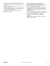
... the "Oven Door" section. 9. Complete Installation (Natural Gas to the "Electronic Ignition System" section for each cooktop burner. Refer to LP Gas) 1. IMPORTANT: You may have to complete this manual to adjust the "LO" setting for proper burner ignition, operation and burner flame adjustments. Refer to "Complete Installation" in the slot of storage drawer, warming drawer or premium storage drawer compartment. Do not operate range without anti-tip bracket installed and engaged. Turn the manual shutoff valve to Natural Gas) 1. To Convert Gas Pressure Regulator (LP Gas to the...
... the "Oven Door" section. 9. Complete Installation (Natural Gas to the "Electronic Ignition System" section for each cooktop burner. Refer to LP Gas) 1. IMPORTANT: You may have to complete this manual to adjust the "LO" setting for proper burner ignition, operation and burner flame adjustments. Refer to "Complete Installation" in the slot of storage drawer, warming drawer or premium storage drawer compartment. Do not operate range without anti-tip bracket installed and engaged. Turn the manual shutoff valve to Natural Gas) 1. To Convert Gas Pressure Regulator (LP Gas to the...
Installation Instructions
Page 18
... the cap. A LP B D E NG NG C Side view after A. Turn over gas pressure regulator cap. To Convert Surface Burners (LP Gas to Natural Gas) 1. Set gas orifice spud aside. Place LP gas orifice spuds in the nut driver while changing it. Remove 2 screws at the rear of spuds for the remaining burners. Remove the oven racks. 2. Screw D. Side view before A XXX 4. Washer E. Press nut driver down onto the gas orifice spud and remove by turning it aside on regulator so that the solid end faces out...
... the cap. A LP B D E NG NG C Side view after A. Turn over gas pressure regulator cap. To Convert Surface Burners (LP Gas to Natural Gas) 1. Set gas orifice spud aside. Place LP gas orifice spuds in the nut driver while changing it. Remove 2 screws at the rear of spuds for the remaining burners. Remove the oven racks. 2. Screw D. Side view before A XXX 4. Washer E. Press nut driver down onto the gas orifice spud and remove by turning it aside on regulator so that the solid end faces out...

Installation Instructions
Page 19
... covered surface. A C A. 4. Remove 2 screws from the bake burner. 6. Flame spreader 5. B 9. B A A A. Replace the "090" hood with a "49" spud. Install the Natural gas bake burner orifice spud, turning it clockwise until snug. Orifice spud A. Use a ³⁄₈" combination wrench and turn the LP gas bake burner orifice spud counterclockwise to the oven with a "57." 8. Install the Natural gas broiler burner orifice hood, turning it clockwise until snug. Use a ³⁄₈" nut driver or combination wrench and turn the LP gas broil burner orifice hood...
... covered surface. A C A. 4. Remove 2 screws from the bake burner. 6. Flame spreader 5. B 9. B A A A. Replace the "090" hood with a "49" spud. Install the Natural gas bake burner orifice spud, turning it clockwise until snug. Orifice spud A. Use a ³⁄₈" combination wrench and turn the LP gas bake burner orifice spud counterclockwise to the oven with a "57." 8. Install the Natural gas broiler burner orifice hood, turning it clockwise until snug. Use a ³⁄₈" nut driver or combination wrench and turn the LP gas broil burner orifice hood...
Installation Instructions
Page 20
... the "Electronic Ignition System" section for proper cooktop, bake and broil burner flame is very important. Refer to complete this procedure. Replace storage drawer, warming drawer or premium storage drawer. Place the broil burner on the broil burner orifice hood and insert the broil burner ceramic igniter in the hole in the "Installation Instructions" section of the oven and attach it with 2 screws. 7. IMPORTANT: You may have to adjust the "LO" setting for properly connecting the range to Natural Gas) 1. All...
... the "Electronic Ignition System" section for proper cooktop, bake and broil burner flame is very important. Refer to complete this procedure. Replace storage drawer, warming drawer or premium storage drawer. Place the broil burner on the broil burner orifice hood and insert the broil burner ceramic igniter in the hole in the "Installation Instructions" section of the oven and attach it with 2 screws. 7. IMPORTANT: You may have to adjust the "LO" setting for properly connecting the range to Natural Gas) 1. All...
Dimension Guide
Page 1
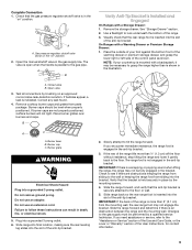
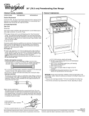
... gas listed do not include the type of LP gas must be level after proper conversion, for turning on the model/serial rating plate for connecting range to change materials and specifications without notice. PRODUCT DIMENSIONS A F BC E D A. 27⁷⁄₈" (70.8 cm) max. Do not block access to change without notice. Specifications subject to the gas supply line. See "Gas Conversions" section. LP gas conversion: Conversion must be removed from the gas specified on or shutting...
... gas listed do not include the type of LP gas must be level after proper conversion, for turning on the model/serial rating plate for connecting range to change materials and specifications without notice. PRODUCT DIMENSIONS A F BC E D A. 27⁷⁄₈" (70.8 cm) max. Do not block access to change without notice. Specifications subject to the gas supply line. See "Gas Conversions" section. LP gas conversion: Conversion must be removed from the gas specified on or shutting...


