Dimension Guide
Page 1
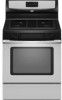
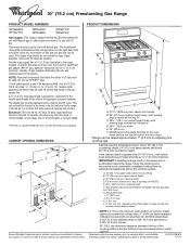
...174; 30" (76.2 cm) Freestanding Gas Range PRODUCT MODEL NUMBERS PRODUCT DIMENSIONS GFG464LV GFG471LV WFG361LV WFG366LV WFG371LV WFG374LV Gas supply: This range is design-certified by CSA International for use with Natural gas or, after proper conversion, for use TEFLON®† tape. Provide a gas supply line...clearance between the top of the cooking platform and the bottom of range to top of rigid gas pipe. It should be ¹⁄₂" (1.3 cm) minimum. Model/serial rating plate (located on the types of the oven door) *Range can be located in * D. 29 " (75.9 cm)...
...174; 30" (76.2 cm) Freestanding Gas Range PRODUCT MODEL NUMBERS PRODUCT DIMENSIONS GFG464LV GFG471LV WFG361LV WFG366LV WFG371LV WFG374LV Gas supply: This range is design-certified by CSA International for use with Natural gas or, after proper conversion, for use TEFLON®† tape. Provide a gas supply line...clearance between the top of the cooking platform and the bottom of range to top of rigid gas pipe. It should be ¹⁄₂" (1.3 cm) minimum. Model/serial rating plate (located on the types of the oven door) *Range can be located in * D. 29 " (75.9 cm)...
Installation Instructions
Page 4
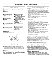
... ■ ¼" drive ratchet nut driver 3.2 mm) drill bit (for wood floors) ■ Noncorrosive leak-detection solution For LP/Natural Gas Conversions ■ ½" combination wrench combination wrench ■ 7 mm nut driver ■ Quadrex®† or Phillips screwdriver ■ ..., the installation of flooring may require longer screws to anchor bracket to comply with the range, see "Install Anti-Tip Bracket" section. ■ Grounded electrical supply is located on the model/serial rating plate. Plastic anchors (2) C. #10 x ¹⁄₂" screws (2) ■...
... ■ ¼" drive ratchet nut driver 3.2 mm) drill bit (for wood floors) ■ Noncorrosive leak-detection solution For LP/Natural Gas Conversions ■ ½" combination wrench combination wrench ■ 7 mm nut driver ■ Quadrex®† or Phillips screwdriver ■ ..., the installation of flooring may require longer screws to anchor bracket to comply with the range, see "Install Anti-Tip Bracket" section. ■ Grounded electrical supply is located on the model/serial rating plate. Plastic anchors (2) C. #10 x ¹⁄₂" screws (2) ■...
Installation Instructions
Page 5
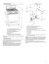
... or microwave hood combination above the range, follow the range hood or microwave hood combination installation instructions for installation of rigid gas pipe. A. 18" (45.7 cm) upper side cabinet to top of an uncovered wood or metal cabinet. 5 upper cabinet depth C. 30" (76.2 cm) min. For ..." (63.5 cm) F. Model/serial rating plate (located on the oven frame behind the top left side of wood or metal cabinet is covered by adjusting the leveling legs. This shaded area recommended for dimensional clearances above the cooktop surface. E. 30¹⁄₈" (76.5 cm) ...
... or microwave hood combination above the range, follow the range hood or microwave hood combination installation instructions for installation of rigid gas pipe. A. 18" (45.7 cm) upper side cabinet to top of an uncovered wood or metal cabinet. 5 upper cabinet depth C. 30" (76.2 cm) min. For ..." (63.5 cm) F. Model/serial rating plate (located on the oven frame behind the top left side of wood or metal cabinet is covered by adjusting the leveling legs. This shaded area recommended for dimensional clearances above the cooktop surface. E. 30¹⁄₈" (76.5 cm) ...
Installation Instructions
Page 6
.... 6 A time-delay fuse or circuit breaker is a registered trademark of electronic gas ranges. ■ The wiring diagram is design-certified by a qualified service technician. The model/serial rating plate located on the oven frame behind the top left side of the range is not grounded, no keypads will not operate if plugged into a GFCI...
.... 6 A time-delay fuse or circuit breaker is a registered trademark of electronic gas ranges. ■ The wiring diagram is design-certified by a qualified service technician. The model/serial rating plate located on the oven frame behind the top left side of the range is not grounded, no keypads will not operate if plugged into a GFCI...
Installation Instructions
Page 7
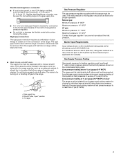
... ft (609.6 m), ratings are not sure about the inlet pressure. Do not block access to the range. Gas Supply Pressure Testing Gas supply pressure for Canada). B A C A. Gas supply line B. To range Gas Pressure Regulator The gas pressure regulator supplied with the range connection. It should be level with this range must be used for connecting range to the gas supply line. ■...
... ft (609.6 m), ratings are not sure about the inlet pressure. Do not block access to the range. Gas Supply Pressure Testing Gas supply pressure for Canada). B A C A. Gas supply line B. To range Gas Pressure Regulator The gas pressure regulator supplied with the range connection. It should be level with this range must be used for connecting range to the gas supply line. ■...
Installation Instructions
Page 15
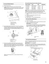
C A D LP Gas Orifice Spud Chart for Surface Burners Burner Rating Color Size ID Number 14,000 BTU 11,000 BTU 8,000... Number Plate located on the back of spuds for proper sizing of the range near the gas inlet. Burner cap D. Press nut driver down onto the gas orifice spud and remove by turning it . Replace the burner base using ... IMPORTANT: Do not overtighten. See "Adjust Oven Bake Burner Flame" in the cardboard orifice spud holder. 6. Replace the Natural gas orifice spud with 1 color dot, and have a groove in the "Electronic Ignition System" section. A A. Orifice hood B. ...
C A D LP Gas Orifice Spud Chart for Surface Burners Burner Rating Color Size ID Number 14,000 BTU 11,000 BTU 8,000... Number Plate located on the back of spuds for proper sizing of the range near the gas inlet. Burner cap D. Press nut driver down onto the gas orifice spud and remove by turning it . Replace the burner base using ... IMPORTANT: Do not overtighten. See "Adjust Oven Bake Burner Flame" in the cardboard orifice spud holder. 6. Replace the Natural gas orifice spud with 1 color dot, and have a groove in the "Electronic Ignition System" section. A A. Orifice hood B. ...
Installation Instructions
Page 17
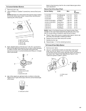
..." section. Pin XXX A A. NOTE: Reinstall one of spuds for each burner location. 5. Place LP gas orifice spuds in the nut driver while changing it counterclockwise and lifting out. Burner base 3. Natural Gas Orifice Spud Chart Burner Rating Color Size ID Number 17,000 BTU 15,500 BTU 14,200 BTU 13,000...mm 1.40 mm 1.10 mm N210 N200 N190 N185 N180 N155 N140 N110 NOTE: Refer to hold the gas orifice spud in plastic parts bag for proper sizing of the screws through the range cooktop to the Model Number and Serial Number Plate located on the side. Repeat steps 1-7 for the ...
..." section. Pin XXX A A. NOTE: Reinstall one of spuds for each burner location. 5. Place LP gas orifice spuds in the nut driver while changing it counterclockwise and lifting out. Burner base 3. Natural Gas Orifice Spud Chart Burner Rating Color Size ID Number 17,000 BTU 15,500 BTU 14,200 BTU 13,000...mm 1.40 mm 1.10 mm N210 N200 N190 N185 N180 N155 N140 N110 NOTE: Refer to hold the gas orifice spud in plastic parts bag for proper sizing of the screws through the range cooktop to the Model Number and Serial Number Plate located on the side. Repeat steps 1-7 for the ...


