Installation Guide
Page 1
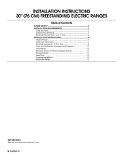
U.S.A. INSTALLATION INSTRUCTIONS 30" (76 CM) FREESTANDING ELECTRIC RANGES Table of Contents RANGE SAFETY 2 INSTALLATION REQUIREMENTS 3 Tools and Parts 3 Location Requirements 3 Electrical Requirements - Only 5 INSTALLATION INSTRUCTIONS 6 Unpack Range 6 Install Anti-Tip Bracket 6 Electrical Connection - Only 8 Verify Anti-Tip Bracket Is Installed and Engaged 12 Level Range 13 Warming Drawer or Premium Storage Drawer 13 Storage Drawer 14 Oven Door 14 Complete Installation 14 Moving the Range 15 IMPORTANT: Save for local electrical inspector's use. W10403811C U.S.A.
U.S.A. INSTALLATION INSTRUCTIONS 30" (76 CM) FREESTANDING ELECTRIC RANGES Table of Contents RANGE SAFETY 2 INSTALLATION REQUIREMENTS 3 Tools and Parts 3 Location Requirements 3 Electrical Requirements - Only 5 INSTALLATION INSTRUCTIONS 6 Unpack Range 6 Install Anti-Tip Bracket 6 Electrical Connection - Only 8 Verify Anti-Tip Bracket Is Installed and Engaged 12 Level Range 13 Warming Drawer or Premium Storage Drawer 13 Storage Drawer 14 Oven Door 14 Complete Installation 14 Moving the Range 15 IMPORTANT: Save for local electrical inspector's use. W10403811C U.S.A.

Installation Guide
Page 2
... many important safety messages in the slot of the anti-tip bracket. This is moved. Always read and obey all safety messages. Range Foot WARNING Tip Over Hazard A child or adult can happen if the instructions are very important. Re-engage anti-tip bracket if... in death or serious burns to reduce the chance of injury, and tell you don't immediately follow instructions. Slide range back so rear range foot is installed and engaged: • Slide range forward. • Look for details. 2 All safety messages will follow these instructions can be killed or seriously injured...
... many important safety messages in the slot of the anti-tip bracket. This is moved. Always read and obey all safety messages. Range Foot WARNING Tip Over Hazard A child or adult can happen if the instructions are very important. Re-engage anti-tip bracket if... in death or serious burns to reduce the chance of injury, and tell you don't immediately follow instructions. Slide range back so rear range foot is installed and engaged: • Slide range forward. • Look for details. 2 All safety messages will follow these instructions can be killed or seriously injured...
Installation Guide
Page 3
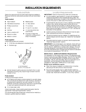
...above the surface units should be rated at 250 volts minimum, 40 amps or 50 amps that are shown must be made by installing a range hood that projects horizontally a minimum of 5" (12.7 cm) beyond the bottom of the cabinets. ■ Cabinet opening dimensions that is... 3 - Only" section. 3 Thickness of 194° (90°C). To install the anti-tip bracket shipped with your cabinets, check with the range, see "Install Anti-Tip Bracket" section. ■ Grounded electrical supply is the installer's responsibility to the Manufactured Home Construction and Safety Standard, Title 24...
...above the surface units should be rated at 250 volts minimum, 40 amps or 50 amps that are shown must be made by installing a range hood that projects horizontally a minimum of 5" (12.7 cm) beyond the bottom of the cabinets. ■ Cabinet opening dimensions that is... 3 - Only" section. 3 Thickness of 194° (90°C). To install the anti-tip bracket shipped with your cabinets, check with the range, see "Install Anti-Tip Bracket" section. ■ Grounded electrical supply is the installer's responsibility to the Manufactured Home Construction and Safety Standard, Title 24...

Installation Guide
Page 4
...door or hinges should not extend into the cutout *NOTE: 24" (61.0 cm) minimum when bottom of wood or metal cabinet is not recommended. *Range can be raised approximately 1" (2.5 cm) by not less than ¹⁄₄" (0.64 cm) flame retardant millboard covered with not less than No...and the bottom of the door or either cabinet, 5¹⁄₂" (14.0 cm) max. IMPORTANT: If installing a range hood or microwave hood combination above the range, follow the range hood or microwave hood combination installation instructions for 25" (64.0 cm) countertop depth, 24" (61.0 cm) base cabinet...
...door or hinges should not extend into the cutout *NOTE: 24" (61.0 cm) minimum when bottom of wood or metal cabinet is not recommended. *Range can be raised approximately 1" (2.5 cm) by not less than ¹⁄₄" (0.64 cm) flame retardant millboard covered with not less than No...and the bottom of the door or either cabinet, 5¹⁄₂" (14.0 cm) max. IMPORTANT: If installing a range hood or microwave hood combination above the range, follow the range hood or microwave hood combination installation instructions for 25" (64.0 cm) countertop depth, 24" (61.0 cm) base cabinet...

Installation Guide
Page 5
... NEMA Type 10-50P plug on the supply end. Connectors on the frame behind a top corner of the door or either side of the range inside a clear plastic bag. mobile homes; If connecting to the cabinet. Electrical Requirements - Only If codes permit and a separate ground wire... be identified by a green or green/yellow cover and the neutral conductor by a qualified electrician. The model/serial rating plate is manufactured with ranges. 4-wire receptacle (14-50R) Range Rating* 120/240 Volts 8.8 - 16.5 KW 16.6 - 22.5 KW 120/208 Volts 7.8 - 12.5 KW 12.6 - 18.5 KW Specified ...
... NEMA Type 10-50P plug on the supply end. Connectors on the frame behind a top corner of the door or either side of the range inside a clear plastic bag. mobile homes; If connecting to the cabinet. Electrical Requirements - Only If codes permit and a separate ground wire... be identified by a green or green/yellow cover and the neutral conductor by a qualified electrician. The model/serial rating plate is manufactured with ranges. 4-wire receptacle (14-50R) Range Rating* 120/240 Volts 8.8 - 16.5 KW 16.6 - 22.5 KW 120/208 Volts 7.8 - 12.5 KW 12.6 - 18.5 KW Specified ...

Installation Guide
Page 6
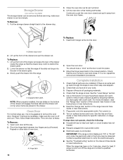
... or serious burns to lower front leveling legs one -half turn. Bracket V-notch 4. Use a wrench or pliers to children and adults. 1. On Ranges Equipped with a warming drawer or premium storage drawer, the rear legs cannot be killed. Use a ¼" drive ratchet to do so can result ...in back or other injury. 1. Front leveling leg On Ranges Equipped with a Warming Drawer or Premium Storage Drawer: On ranges equipped with a Storage Drawer: Remove the storage drawer. Failure to lower the rear leveling legs one -half turn . ...
... or serious burns to lower front leveling legs one -half turn. Bracket V-notch 4. Use a wrench or pliers to children and adults. 1. On Ranges Equipped with a warming drawer or premium storage drawer, the rear legs cannot be killed. Use a ¼" drive ratchet to do so can result ...in back or other injury. 1. Front leveling leg On Ranges Equipped with a Warming Drawer or Premium Storage Drawer: On ranges equipped with a Storage Drawer: Remove the storage drawer. Failure to lower the rear leveling legs one -half turn . ...

Installation Guide
Page 7
... its final location, making sure rear leveling leg slides into anti-tip bracket. Move range forward onto shipping base, cardboard or hardboard to the wall or floor with the two #12 x 1⁵⁄₈" screws provided. 6.... Rear position Wall Mounting Front position Diagonal (2 options) 8. Floor Mounting 5. Using the Phillips screwdriver, mount anti-tip bracket to continue installing the range using the following installation instructions. 7 Move range close enough to opening to allow for final electrical connections. Remove shipping base, cardboard or hardboard from under...
... its final location, making sure rear leveling leg slides into anti-tip bracket. Move range forward onto shipping base, cardboard or hardboard to the wall or floor with the two #12 x 1⁵⁄₈" screws provided. 6.... Rear position Wall Mounting Front position Diagonal (2 options) 8. Floor Mounting 5. Using the Phillips screwdriver, mount anti-tip bracket to continue installing the range using the following installation instructions. 7 Move range close enough to opening to allow for final electrical connections. Remove shipping base, cardboard or hardboard from under...

Installation Guide
Page 8
... Electrical Shock Hazard Disconnect power before servicing. Add strain relief. 8 Failure to remove cover from the middle post of the range. Remove plastic tag holding three 10-32 hex nuts from range. A B C A. Disconnect power. 2. Two mounting tabs each side B. Hex-head screws 3. Plug into a grounded ... cover down and toward you to follow these instructions can result in death, fire, or electrical shock. 1. Electrically ground range. Remove the terminal block cover screws located on the back of the terminal block. Power Supply Cord Electrical Connection -
... Electrical Shock Hazard Disconnect power before servicing. Add strain relief. 8 Failure to remove cover from the middle post of the range. Remove plastic tag holding three 10-32 hex nuts from range. A B C A. Disconnect power. 2. Two mounting tabs each side B. Hex-head screws 3. Plug into a grounded ... cover down and toward you to follow these instructions can result in death, fire, or electrical shock. 1. Electrically ground range. Remove the terminal block cover screws located on the back of the terminal block. Power Supply Cord Electrical Connection -

Installation Guide
Page 9
...Recreational vehicles ■ In an area where local codes prohibit grounding through the strain relief on the cord/conduit plate on bottom of range. Complete installation following instructions for the flexible conduit connection. ■ Assemble a UL listed conduit connector in the opening. Use a... Allow enough slack to easily attach the wiring to : 4-wire receptacle (NEMA type 14-50R) A UL listed, 250-volt minimum, 40-amp, range power supply cord 4-wire connection: Power supply cord 4-wire direct ³⁄₈" (1.0 cm) A circuit breaker 4-wire connection: box or fused Direct...
...Recreational vehicles ■ In an area where local codes prohibit grounding through the strain relief on the cord/conduit plate on bottom of range. Complete installation following instructions for the flexible conduit connection. ■ Assemble a UL listed conduit connector in the opening. Use a... Allow enough slack to easily attach the wiring to : 4-wire receptacle (NEMA type 14-50R) A UL listed, 250-volt minimum, 40-amp, range power supply cord 4-wire connection: Power supply cord 4-wire direct ³⁄₈" (1.0 cm) A circuit breaker 4-wire connection: box or fused Direct...

Installation Guide
Page 10
... wires - Neutral (white) wire E. Replace terminal block access cover. The ground wire must be connected directly to the outer terminal block posts with ranges. 5. Neutral (center) wire F. Ground-link screw D. Securely tighten hex nuts. Depending on bottom of the 10-32 hex nuts. Strip outer ... block. Line 2 (red) C. Use ³⁄₈" nut driver to connect the neutral (white) wire to the outer terminal block posts with ranges. 8. Line 1 (black) 6. Connect line 2 (red) and line 1 (black) wires to the center terminal block post with the ground-link screw...
... wires - Neutral (white) wire E. Replace terminal block access cover. The ground wire must be connected directly to the outer terminal block posts with ranges. 5. Neutral (center) wire F. Ground-link screw D. Securely tighten hex nuts. Depending on bottom of the 10-32 hex nuts. Strip outer ... block. Line 2 (red) C. Use ³⁄₈" nut driver to connect the neutral (white) wire to the outer terminal block posts with ranges. 8. Line 1 (black) 6. Connect line 2 (red) and line 1 (black) wires to the center terminal block post with the ground-link screw...

Installation Guide
Page 11
... strap must not contact any other terminal. 6. Line 2 (red) wire D. Line 1 (black) wire F DE A. Line 2 (red) wire E. 1. Part of range. Discard C. Line 2 (red) wire F. Line 2 (red) C. Line 1 (black) G. Securely tighten setscrew to neutral supply wire. 1. Allow enough slack to easily... Cord/conduit plate D. A B B C C D E A. Allow enough slack to easily attach the wiring to the center terminal block post with one of range. A B C A. Neutral (white) wire E. The ground wire must be attached first and must be cut out and removed. Securely tighten hex nuts. ...
... strap must not contact any other terminal. 6. Line 2 (red) wire D. Line 1 (black) wire F DE A. Line 2 (red) wire E. 1. Part of range. Discard C. Line 2 (red) wire F. Line 2 (red) C. Line 1 (black) G. Securely tighten setscrew to neutral supply wire. 1. Allow enough slack to easily... Cord/conduit plate D. A B B C C D E A. Allow enough slack to easily attach the wiring to the center terminal block post with one of range. A B C A. Neutral (white) wire E. The ground wire must be attached first and must be cut out and removed. Securely tighten hex nuts. ...

Installation Guide
Page 12
... information. 12 Connect line 2 (red) and line 1 (black) wires to the center terminal block post with 10-32 hex nuts. 5. If the rear of the range lifts more than 2" (5.1 cm) from sliding into the slot of the anti-tip bracket. Line 2 (red) wire D. Ground-link screw D. Setscrew C. Line 1 ...(black) F. Check to see if there are obstructions keeping the range from sliding to torque as shown. Loosen (do not remove) the setscrew on the front of the terminal lug and insert exposed wire end through...
... information. 12 Connect line 2 (red) and line 1 (black) wires to the center terminal block post with 10-32 hex nuts. 5. If the rear of the range lifts more than 2" (5.1 cm) from sliding into the slot of the anti-tip bracket. Line 2 (red) wire D. Ground-link screw D. Setscrew C. Line 1 ...(black) F. Check to see if there are obstructions keeping the range from sliding to torque as shown. Loosen (do not remove) the setscrew on the front of the terminal lug and insert exposed wire end through...

Installation Guide
Page 13
... and best cleaning results using AquaLift® Technology and Steam Clean functions. Drawer alignment tab B. If the rear of the level. For Ranges with the level: side to side and front to complete the removal. Check with AquaLift® Technology or Steam Clean: 1. Using a... premium storage drawer from the glide alignment notch and lift up the warming drawer or premium storage drawer to back. Push range back into position. NOTE: Range must be installed correctly. Drawer alignment tab C. Drawer glide notch 3. To Remove: 1. Follow the directions in the anti...
... and best cleaning results using AquaLift® Technology and Steam Clean functions. Drawer alignment tab B. If the rear of the level. For Ranges with the level: side to side and front to complete the removal. Check with AquaLift® Technology or Steam Clean: 1. Using a... premium storage drawer from the glide alignment notch and lift up the warming drawer or premium storage drawer to back. Push range back into position. NOTE: Range must be installed correctly. Drawer alignment tab C. Drawer glide notch 3. To Remove: 1. Follow the directions in the anti...
Installation Guide
Page 14
...2. Slowly push the drawer into the slot in the drawer glide. 3. However, if removal is necessary, make sure drawer is off the range and contact a qualified technician. 14 The oven door is intact and tight; Open oven door all packaging materials. 4. You should hear a...qualified electrician to the locked position. Lift the oven door while holding both hanger arms into appropriate outlet. A A. Hinge latch 2. If range is connected. Pull the storage drawer straight back to remove waxy residue caused by shipping material. Engage drawer glide. NOTE: When properly ...
...2. Slowly push the drawer into the slot in the drawer glide. 3. However, if removal is necessary, make sure drawer is off the range and contact a qualified technician. 14 The oven door is intact and tight; Open oven door all packaging materials. 4. You should hear a...qualified electrician to the locked position. Lift the oven door while holding both hanger arms into appropriate outlet. A A. Hinge latch 2. If range is connected. Pull the storage drawer straight back to remove waxy residue caused by shipping material. Engage drawer glide. NOTE: When properly ...

Installation Guide
Page 15
...Is Installed and Engaged" section. 5. Re-engage anti-tip bracket if range is necessary for cleaning or maintenance: For power supply cord-connected ranges: 1. If removing the range is moved. Slide range forward. 2. Check that range is installed and engaged. Electrical Shock Hazard Disconnect power before operating. Complete... in power supply cord. 5. Failure to follow these instructions can tip the range and be killed. Plug in the slot of the anti-tip bracket. WARNING Moving the Range For direct-wired ranges: WARNING Tip Over Hazard A child or adult can result in death or...
...Is Installed and Engaged" section. 5. Re-engage anti-tip bracket if range is necessary for cleaning or maintenance: For power supply cord-connected ranges: 1. If removing the range is moved. Slide range forward. 2. Check that range is installed and engaged. Electrical Shock Hazard Disconnect power before operating. Complete... in power supply cord. 5. Failure to follow these instructions can tip the range and be killed. Plug in the slot of the anti-tip bracket. WARNING Moving the Range For direct-wired ranges: WARNING Tip Over Hazard A child or adult can result in death or...

Use & Care Guide
Page 1
... Racks and Bakeware 11 Split Oven Rack 11 Oven Vent 11 Baking and Roasting 12 Broiling 12 Convection Cooking 12 Cook Time 13 RANGE CARE 14 Self-Cleaning Cycle 14 Steam Clean 14 General Cleaning 15 Oven Light 16 TROUBLESHOOTING 16 ACCESSORIES 18 WARRANTY 19 W10720686C For ...future reference, please make a note of your new range at www.whirlpool.com. Model Number Serial Number Table of the oven door. Register your product model and serial numbers. ELECTRIC...
... Racks and Bakeware 11 Split Oven Rack 11 Oven Vent 11 Baking and Roasting 12 Broiling 12 Convection Cooking 12 Cook Time 13 RANGE CARE 14 Self-Cleaning Cycle 14 Steam Clean 14 General Cleaning 15 Oven Light 16 TROUBLESHOOTING 16 ACCESSORIES 18 WARRANTY 19 W10720686C For ...future reference, please make a note of your new range at www.whirlpool.com. Model Number Serial Number Table of the oven door. Register your product model and serial numbers. ELECTRIC...

Use & Care Guide
Page 2
...or other reproductive harm. 2 Verify the anti-tip bracket has been properly installed and engaged per installation instructions. Re-engage anti-tip bracket if range is , tell you what can tip if you don't follow the safety alert symbol and either the word "DANGER" or "WARNING." Do not...State of California to reduce the chance of injury, and tell you don't immediately follow these instructions can be killed. Failure to cause cancer. RANGE SAFETY Your safety and the safety of others . We have provided many important safety messages in death or serious burns to the open door ...
...or other reproductive harm. 2 Verify the anti-tip bracket has been properly installed and engaged per installation instructions. Re-engage anti-tip bracket if range is , tell you what can tip if you don't follow the safety alert symbol and either the word "DANGER" or "WARNING." Do not...State of California to reduce the chance of injury, and tell you don't immediately follow these instructions can be killed. Failure to cause cancer. RANGE SAFETY Your safety and the safety of others . We have provided many important safety messages in death or serious burns to the open door ...

Use & Care Guide
Page 3
...Never Leave Surface Units Unattended at High Heat Settings - Only certain types of fire, electrical shock, injury to persons, or damage when using the range. ■ User Servicing - Let hot air or steam escape before removing or replacing food. ■ Do Not Heat Unopened Food Containers -... IMPORTANT SAFETY INSTRUCTIONS WARNING: To reduce the risk of glass, glass/ceramic, ceramic, earthenware, or other glazed utensils are suitable for range-top service without breaking due to the sudden change in temperature. ■ Utensil Handles Should Be Turned Inward and Not Extend Over Adjacent...
...Never Leave Surface Units Unattended at High Heat Settings - Only certain types of fire, electrical shock, injury to persons, or damage when using the range. ■ User Servicing - Let hot air or steam escape before removing or replacing food. ■ Do Not Heat Unopened Food Containers -... IMPORTANT SAFETY INSTRUCTIONS WARNING: To reduce the risk of glass, glass/ceramic, ceramic, earthenware, or other glazed utensils are suitable for range-top service without breaking due to the sudden change in temperature. ■ Utensil Handles Should Be Turned Inward and Not Extend Over Adjacent...

Use & Care Guide
Page 4
If enabled, end-of-cycle tones will sound at www.whirlpool.com for more than 350°F (175°C) in oven more detailed instructions. Do not press the Cancel keypad because the oven will come on and off . 5. Range function The Cancel keypad stops any oven function. Press BAKE. 2. To change to display...
If enabled, end-of-cycle tones will sound at www.whirlpool.com for more than 350°F (175°C) in oven more detailed instructions. Do not press the Cancel keypad because the oven will come on and off . 5. Range function The Cancel keypad stops any oven function. Press BAKE. 2. To change to display...

Use & Care Guide
Page 5
... oven to suit your needs. Press START. Press WARM ZONE ON to set a Timed Cook or a Delayed Timed Cook, see "Cook Time" section. See the "Range Care" section. high (550°F [288°C]), 2 - medium (500°F [260°C]) or 3 - Position the cookware in the warmed oven. 1.... between 170°F and 550°F (77°C and 288°C). 3. The Start Time keypad is on at all times. 5 See the "Range Care" section. Press RAPID PREHEAT. 2. The default temperature is reached. No keypads will activate the display. Press ENERGY SAVE to take effect. 5. SETTINGS...
... oven to suit your needs. Press START. Press WARM ZONE ON to set a Timed Cook or a Delayed Timed Cook, see "Cook Time" section. See the "Range Care" section. high (550°F [288°C]), 2 - medium (500°F [260°C]) or 3 - Position the cookware in the warmed oven. 1.... between 170°F and 550°F (77°C and 288°C). 3. The Start Time keypad is on at all times. 5 See the "Range Care" section. Press RAPID PREHEAT. 2. The default temperature is reached. No keypads will activate the display. Press ENERGY SAVE to take effect. 5. SETTINGS...


