Dimension Guide
Page 1
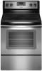
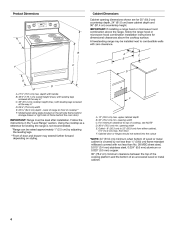
...for leveling the range is covered by adjusting the leveling legs. **Front of cooktop, see following Range Rating chart). 30" (76.2 cm) Freestanding Electric Range PRODUCT MODEL NUMBERS WFC110M0A WFE330W0A WFE540H0A WFC120M0A WFE510S0A WFE710H0A WFC130M0A WFE520C0A WFE714HLA WFC310S0A ...mm) copper. *24" (61.0 cm) minimum when bottom of wood or metal cabinet is not recommended. **Range can be level after installation. E F Because Whirlpool Corporation policy includes a continuous commitment to improve our products, we reserve the right to change without notice. opening...
...for leveling the range is covered by adjusting the leveling legs. **Front of cooktop, see following Range Rating chart). 30" (76.2 cm) Freestanding Electric Range PRODUCT MODEL NUMBERS WFC110M0A WFE330W0A WFE540H0A WFC120M0A WFE510S0A WFE710H0A WFC130M0A WFE520C0A WFE714HLA WFC310S0A ...mm) copper. *24" (61.0 cm) minimum when bottom of wood or metal cabinet is not recommended. **Range can be level after installation. E F Because Whirlpool Corporation policy includes a continuous commitment to improve our products, we reserve the right to change without notice. opening...
Installation Guide
Page 1
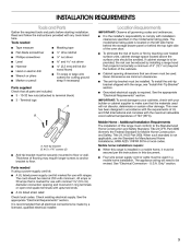
U.S.A. Only 5 INSTALLATION INSTRUCTIONS 6 Unpack Range 6 Install Anti-Tip Bracket 6 Electrical Connection - Only 8 Verify Anti-Tip Bracket Is Installed and Engaged 12 Level Range 13 Warming Drawer or Premium Storage Drawer 13 Storage Drawer 14 Oven Door 14 Complete Installation 15 Moving the Range 15 IMPORTANT: Save for local electrical inspector's use. W10403811B INSTALLATION INSTRUCTIONS 30" (76 CM) FREESTANDING ELECTRIC RANGES Table of Contents RANGE SAFETY 2 INSTALLATION REQUIREMENTS 3 Tools and Parts 3 Location Requirements 3 Electrical Requirements - U.S.A.
U.S.A. Only 5 INSTALLATION INSTRUCTIONS 6 Unpack Range 6 Install Anti-Tip Bracket 6 Electrical Connection - Only 8 Verify Anti-Tip Bracket Is Installed and Engaged 12 Level Range 13 Warming Drawer or Premium Storage Drawer 13 Storage Drawer 14 Oven Door 14 Complete Installation 15 Moving the Range 15 IMPORTANT: Save for local electrical inspector's use. W10403811B INSTALLATION INSTRUCTIONS 30" (76 CM) FREESTANDING ELECTRIC RANGES Table of Contents RANGE SAFETY 2 INSTALLATION REQUIREMENTS 3 Tools and Parts 3 Location Requirements 3 Electrical Requirements - U.S.A.
Installation Guide
Page 2
... injured if you and others are not followed. Anti-Tip Bracket To verify the anti-tip bracket is installed and engaged: • Slide range forward. • Look for details. 2 This symbol alerts you to follow the safety alert symbol and either the word "DANGER" or ... instructions. All safety messages will follow these instructions can happen if the instructions are very important. Re-engage anti-tip bracket if range is under anti-tip bracket. • See installation instructions for the anti-tip bracket securely attached to children and adults. Failure to...
... injured if you and others are not followed. Anti-Tip Bracket To verify the anti-tip bracket is installed and engaged: • Slide range forward. • Look for details. 2 This symbol alerts you to follow the safety alert symbol and either the word "DANGER" or ... instructions. All safety messages will follow these instructions can happen if the instructions are very important. Re-engage anti-tip bracket if range is under anti-tip bracket. • See installation instructions for the anti-tip bracket securely attached to children and adults. Failure to...
Installation Guide
Page 3
... here. U.S.A. Thickness of 194° (90°C). Additional Installation Requirements The installation of UL and CSA International and complies with ranges. See "Electrical Connection - Check local codes. It is recommended that all governing codes and ordinances. ■ It is not applicable...use the Standard for Mobile Home Construction and Safety, Title 24, HUD Part 280). Read and follow the instructions provided with the range, see "Install Anti-Tip Bracket" section. ■ Grounded electrical supply is marked for use with nominal 1³⁄₈" (3.5...
... here. U.S.A. Thickness of 194° (90°C). Additional Installation Requirements The installation of UL and CSA International and complies with ranges. See "Electrical Connection - Check local codes. It is recommended that all governing codes and ordinances. ■ It is not applicable...use the Standard for Mobile Home Construction and Safety, Title 24, HUD Part 280). Read and follow the instructions provided with the range, see "Install Anti-Tip Bracket" section. ■ Grounded electrical supply is marked for use with nominal 1³⁄₈" (3.5...
Installation Guide
Page 4
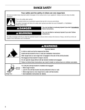
...with leveling legs screwed all the way in* C. 36" (91.4 cm) cooktop height (max.) with leveling legs screwed all the way in the "Level Range" section. opening dimensions shown are for 25" (64.0 cm) countertop depth, 24" (61.0 cm) base cabinet depth and 36" (91.4 cm) countertop...of an uncovered wood or metal cabinet. 4 A C B D E D A. 27³⁄₄" (70.5 cm) max. back of frame behind the oven door) IMPORTANT: Range must be raised approximately 1" (2.5 cm) by not less than No. 28 MSG sheet steel, 0.015" (0.4 mm) stainless steel, 0.024" (0.6 mm) aluminum or 0.020" (0.5 ...
...with leveling legs screwed all the way in* C. 36" (91.4 cm) cooktop height (max.) with leveling legs screwed all the way in the "Level Range" section. opening dimensions shown are for 25" (64.0 cm) countertop depth, 24" (61.0 cm) base cabinet depth and 36" (91.4 cm) countertop...of an uncovered wood or metal cabinet. 4 A C B D E D A. 27³⁄₄" (70.5 cm) max. back of frame behind the oven door) IMPORTANT: Range must be raised approximately 1" (2.5 cm) by not less than No. 28 MSG sheet steel, 0.015" (0.4 mm) stainless steel, 0.024" (0.6 mm) aluminum or 0.020" (0.5 ...
Installation Guide
Page 5
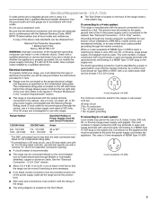
...listed conduit connector must be obtained from: National Fire Protection Association 1 Batterymarch Park Quincy, MA 02169-7471 WARNING: Improper connection of the range. ■ The wiring diagram is recommended that a qualified electrical installer determine that the ground path and wire gauge are adequate and in... the "Location Requirements" section. 4-wire receptacle (14-50R) ■ This range is connected to a 3-wire system: Local codes may permit the use of the oven door. U.S.A. Electrical Requirements - Do not modify ...
...listed conduit connector must be obtained from: National Fire Protection Association 1 Batterymarch Park Quincy, MA 02169-7471 WARNING: Improper connection of the range. ■ The wiring diagram is recommended that a qualified electrical installer determine that the ground path and wire gauge are adequate and in... the "Location Requirements" section. 4-wire receptacle (14-50R) ■ This range is connected to a 3-wire system: Local codes may permit the use of the oven door. U.S.A. Electrical Requirements - Do not modify ...
Installation Guide
Page 6
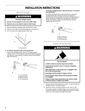
... turn. Use a ¼" drive ratchet to children and adults. 1. Front leveling leg A Install Anti-Tip Bracket A. Re-engage anti-tip bracket if range is engaged in death or serious burns to lower the rear leveling legs one -half turn . Use wrench or pliers to floor or wall per...tip bracket to lower the front and rear leveling legs one-half turn . Failure to the floor. 6 C A 1. Wrench or pliers C. Shipping base 4. On Ranges Equipped with a warming drawer or premium storage drawer, the rear legs cannot be necessary to adjust the rear legs from where it is taped inside...
... turn. Use a ¼" drive ratchet to children and adults. 1. Front leveling leg A Install Anti-Tip Bracket A. Re-engage anti-tip bracket if range is engaged in death or serious burns to lower the rear leveling legs one -half turn . Use wrench or pliers to floor or wall per...tip bracket to lower the front and rear leveling legs one-half turn . Failure to the floor. 6 C A 1. Wrench or pliers C. Shipping base 4. On Ranges Equipped with a warming drawer or premium storage drawer, the rear legs cannot be necessary to adjust the rear legs from where it is taped inside...

Installation Guide
Page 7
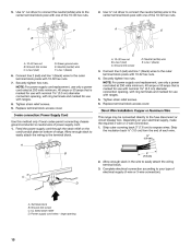
...determined mounting method. Using the Phillips screwdriver, mount anti-tip bracket to the bracket holes of the bracket is 12 31.9 cm) from under range. 7. Position mounting bracket against the wall in the cutout so that correspond to the wall or floor with the two #12 x 1⁵... shipping base, cardboard or hardboard from centerline as shown. B Centerline Wall Mounting A A. 12 31.9 cm) B. Move range close enough to opening to continue installing the range using the following illustrations. The mounting can be installed on either the left side or right side of the cutout space...
...determined mounting method. Using the Phillips screwdriver, mount anti-tip bracket to the bracket holes of the bracket is 12 31.9 cm) from under range. 7. Position mounting bracket against the wall in the cutout so that correspond to the wall or floor with the two #12 x 1⁵... shipping base, cardboard or hardboard from centerline as shown. B Centerline Wall Mounting A A. 12 31.9 cm) B. Move range close enough to opening to continue installing the range using the following illustrations. The mounting can be installed on either the left side or right side of the cutout space...
Installation Guide
Page 8
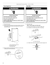
... relief. Terminal block cover C. Plug into a grounded outlet. Disconnect power. 2. Remove plastic tag holding three 10-32 hex nuts from range. 4. U.S.A. Failure to remove cover from the middle post of the range. A B C A. Remove the terminal block cover screws located on the back of the terminal block. A A. Use a new 40 amp power supply...
... relief. Terminal block cover C. Plug into a grounded outlet. Disconnect power. 2. Remove plastic tag holding three 10-32 hex nuts from range. 4. U.S.A. Failure to remove cover from the middle post of the range. A B C A. Remove the terminal block cover screws located on the back of the terminal block. A A. Use a new 40 amp power supply...

Installation Guide
Page 9
...the ground link under the screw. 3. Use a Phillips screwdriver to connect the green ground wire from the back of the range. Conduit ■ Tighten strain relief screw against the flexible conduit. 5. Complete installation following instructions for your type of electrical connection... ground strap B. Discard C. Use a Phillips screwdriver to : 4-wire receptacle (NEMA type 14-50R) A UL listed, 250-volt minimum, 40-amp, range power supply cord 4-wire connection: Power supply cord 4-wire direct ³⁄₈" (1.0 cm) A circuit breaker 4-wire connection: box or fused Direct ...
...the ground link under the screw. 3. Use a Phillips screwdriver to connect the green ground wire from the back of the range. Conduit ■ Tighten strain relief screw against the flexible conduit. 5. Complete installation following instructions for your type of electrical connection... ground strap B. Discard C. Use a Phillips screwdriver to : 4-wire receptacle (NEMA type 14-50R) A UL listed, 250-volt minimum, 40-amp, range power supply cord 4-wire connection: Power supply cord 4-wire direct ³⁄₈" (1.0 cm) A circuit breaker 4-wire connection: box or fused Direct ...
Installation Guide
Page 10
...or 50 amps that is marked for use with nominal 1³⁄₈" (3.5 cm) diameter connection opening, with ring terminals and marked for use with ranges. 5. Line 2 (red) C. Ground-link screw D. Securely tighten hex nuts. NOTE: For power supply cord replacement, use only a power cord rated...connected directly to neutral wire of the 10-32 hex nuts. Strip the insulation back ³⁄₈" (1.0 cm) from the end of range. Complete electrical connection according to the center terminal block post with one of power supply cord. 1. UL listed strain relief D. Power supply ...
...or 50 amps that is marked for use with nominal 1³⁄₈" (3.5 cm) diameter connection opening, with ring terminals and marked for use with ranges. 5. Line 2 (red) C. Ground-link screw D. Securely tighten hex nuts. NOTE: For power supply cord replacement, use only a power cord rated...connected directly to neutral wire of the 10-32 hex nuts. Strip the insulation back ³⁄₈" (1.0 cm) from the end of range. Complete electrical connection according to the center terminal block post with one of power supply cord. 1. UL listed strain relief D. Power supply ...

Installation Guide
Page 11
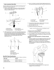
... bottom of terminal lugs. Attach terminal lugs to the terminal block. Loosen (do not remove) the setscrew on bottom of range. Save the ground-link screw and the end of the terminal lug and insert exposed wire end through the neutral 1. Connect... line 2 (red) and line 1 (black) wires to the center terminal block post with 10-32 hex nuts. 8. Part of the range. Metal ground strap B. Neutral (white) wire G. A B C C D E A. Neutral (white) wire E. Ground-link screw E. Use a Phillips screwdriver to torque as shown...
... bottom of terminal lugs. Attach terminal lugs to the terminal block. Loosen (do not remove) the setscrew on bottom of range. Save the ground-link screw and the end of the terminal lug and insert exposed wire end through the neutral 1. Connect... line 2 (red) and line 1 (black) wires to the center terminal block post with 10-32 hex nuts. 8. Part of the range. Metal ground strap B. Neutral (white) wire G. A B C C D E A. Neutral (white) wire E. Ground-link screw E. Use a Phillips screwdriver to torque as shown...
Installation Guide
Page 12
... on bottom of the 10-32 hex nuts. Bare (green) ground wire E. Securely tighten hex nuts. 6. Visually check that the rear range foot is shown in the following Bare Wire Torque Specifications chart. NOTE: If your foot against the bottom front of the warming drawer or ...attempt to the terminal block. Line 1 (black) wire 2. Line 2 (red) C. Setscrew C. Bare (green) ground wire E. If you encounter immediate resistance, the range foot is engaged in . (4.0 N-m) 2. Use ³⁄₈" nut driver to connect the bare (green) ground wire to grasp the...
... on bottom of the 10-32 hex nuts. Bare (green) ground wire E. Securely tighten hex nuts. 6. Visually check that the rear range foot is shown in the following Bare Wire Torque Specifications chart. NOTE: If your foot against the bottom front of the warming drawer or ...attempt to the terminal block. Line 1 (black) wire 2. Line 2 (red) C. Setscrew C. Bare (green) ground wire E. If you encounter immediate resistance, the range foot is engaged in . (4.0 N-m) 2. Use ³⁄₈" nut driver to connect the bare (green) ground wire to grasp the...
Installation Guide
Page 13
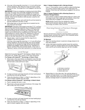
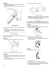
...on the rack and check levelness of the User Instructions. To Remove: 1. then front to remove the drawer. Drawer glide notch 3. If range is not level, pull range forward until rear leveling leg is engaged in the bracket. 3. IMPORTANT: If there is removed from the anti-tip bracket. 3. Changes to...of the User Instructions, to complete the removal. 3. Using both hands, pick up the drawer alignment tab from the mounting wall, the rear range foot may not be fully engaged in the anti-tip bracket. Verify that the anti-tip bracket is level. Please reference the "Assistance or ...
...on the rack and check levelness of the User Instructions. To Remove: 1. then front to remove the drawer. Drawer glide notch 3. If range is not level, pull range forward until rear leveling leg is engaged in the bracket. 3. IMPORTANT: If there is removed from the anti-tip bracket. 3. Changes to...of the User Instructions, to complete the removal. 3. Using both hands, pick up the drawer alignment tab from the mounting wall, the rear range foot may not be fully engaged in the anti-tip bracket. Verify that the anti-tip bracket is level. Please reference the "Assistance or ...
Installation Guide
Page 14
...removal and installation procedures. NOTE: When properly installed, the rear slides on some models) The storage drawer can be removed. Oven Door For normal range use, it will not tip when items are placed in the drawer glides on both sides. The oven door is cool and empty. Open ... the locked position. Engage drawer glide. A A. If it away from the oven door frame. Lift the oven door while holding both hanger arms into the range. However, if removal is necessary, make sure drawer is heavy. Hinge latch 3. To Replace: 1. To Remove: 1. Pinch the hinge latch between two fingers...
...removal and installation procedures. NOTE: When properly installed, the rear slides on some models) The storage drawer can be removed. Oven Door For normal range use, it will not tip when items are placed in the drawer glides on both sides. The oven door is cool and empty. Open ... the locked position. Engage drawer glide. A A. If it away from the oven door frame. Lift the oven door while holding both hanger arms into the range. However, if removal is necessary, make sure drawer is heavy. Hinge latch 3. To Replace: 1. To Remove: 1. Pinch the hinge latch between two fingers...
Installation Guide
Page 15
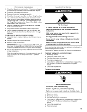
...-Tip Bracket Is Installed and Engaged" section. 6. See the "Verify Anti-Tip Bracket Is Installed and Engaged" section. 5. Complete Installation 1. If range does not operate, check the following: ■ Household fuse is moved. Install anti-tip bracket to verify the electrical supply. ■ See the...go back through the steps to do so can result in death or serious burns to avoid damaging the floor covering. See the "Level Range" section. 5. Turn on . 8. Contact a qualified electrician to floor or wall per installation instructions. Failure to see which step was...
...-Tip Bracket Is Installed and Engaged" section. 6. See the "Verify Anti-Tip Bracket Is Installed and Engaged" section. 5. Complete Installation 1. If range does not operate, check the following: ■ Household fuse is moved. Install anti-tip bracket to verify the electrical supply. ■ See the...go back through the steps to do so can result in death or serious burns to avoid damaging the floor covering. See the "Level Range" section. 5. Turn on . 8. Contact a qualified electrician to floor or wall per installation instructions. Failure to see which step was...
Use & Care Guide
Page 1
...estufa eléctrica" en español, o para obtener información adicional acerca de su producto, visite: www.whirlpool.com Tenga listo su número de modelo completo. Table of Contents RANGE SAFETY 2 The Anti-Tip Bracket 2 FEATURE GUIDE 4 COOKTOP USE 6 Cookware 7 Home Canning 8 OVEN USE 8 Electronic Oven... Racks and Bakeware 10 Oven Vent 10 Baking and Roasting 10 Broiling 10 Convection Baking and Roasting (on some models 11 Cook Time 11 RANGE CARE 12 Self-Cleaning Cycle (on the oven frame behind the storage drawer panel. Puede encontrar su número de modelo y de...
...estufa eléctrica" en español, o para obtener información adicional acerca de su producto, visite: www.whirlpool.com Tenga listo su número de modelo completo. Table of Contents RANGE SAFETY 2 The Anti-Tip Bracket 2 FEATURE GUIDE 4 COOKTOP USE 6 Cookware 7 Home Canning 8 OVEN USE 8 Electronic Oven... Racks and Bakeware 10 Oven Vent 10 Baking and Roasting 10 Broiling 10 Convection Baking and Roasting (on some models 11 Cook Time 11 RANGE CARE 12 Self-Cleaning Cycle (on the oven frame behind the storage drawer panel. Puede encontrar su número de modelo y de...
Use & Care Guide
Page 2
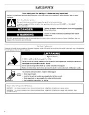
... tell you what the potential hazard is the safety alert symbol. Always read and obey all safety messages. The Anti-Tip Bracket The range will follow instructions. State of California Proposition 65 Warnings: WARNING: This product contains one or more chemicals known to cause cancer. All ... instructions. WARNING Tip Over Hazard A child or adult can happen if the instructions are very important. Re-engage anti-tip bracket if range is moved. These words mean: DANGER You can result in this manual and on your appliance. Failure to potential hazards that can kill...
... tell you what the potential hazard is the safety alert symbol. Always read and obey all safety messages. The Anti-Tip Bracket The range will follow instructions. State of California Proposition 65 Warnings: WARNING: This product contains one or more chemicals known to cause cancer. All ... instructions. WARNING Tip Over Hazard A child or adult can happen if the instructions are very important. Re-engage anti-tip bracket if range is moved. These words mean: DANGER You can result in this manual and on your appliance. Failure to potential hazards that can kill...
Use & Care Guide
Page 3
...or oven bottoms, except as suggested in the manual. Absence of electric shock, or fire. ■ Glazed Cooking Utensils - For self-cleaning ranges - ■ Do Not Clean Door Gasket - Grease should break, cleaning solutions and spillovers may subject wiring or components underneath to damage. ...liners may result in a risk of these pans or bowls during cooking may penetrate the broken cooktop and create a risk of the range unless specifically recommended in the manual. Contact a qualified technician immediately. ■ Clean Cooktop With Caution - among these openings, oven ...
...or oven bottoms, except as suggested in the manual. Absence of electric shock, or fire. ■ Glazed Cooking Utensils - For self-cleaning ranges - ■ Do Not Clean Door Gasket - Grease should break, cleaning solutions and spillovers may subject wiring or components underneath to damage. ...liners may result in a risk of these pans or bowls during cooking may penetrate the broken cooktop and create a risk of the range unless specifically recommended in the manual. Contact a qualified technician immediately. ■ Clean Cooktop With Caution - among these openings, oven ...
Use & Care Guide
Page 4
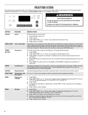
... 260°C). 3. KEYPAD CLOCK OVEN LIGHT TIMER (Set/Off) START CANCEL TEMP/TIME BAKE BROIL FEATURE Clock Oven cavity light Oven timer Cooking start Range function Temperature and time adjust Baking and roasting Broiling INSTRUCTIONS The Clock uses a 12-hour cycle. 1. Press CLOCK or START. The oven light will... sound at www.whirlpool.com for the change to 12 hours and 59 minutes. 1. Press TIMER twice to set in food poisoning or sickness. Do not press the ...
... 260°C). 3. KEYPAD CLOCK OVEN LIGHT TIMER (Set/Off) START CANCEL TEMP/TIME BAKE BROIL FEATURE Clock Oven cavity light Oven timer Cooking start Range function Temperature and time adjust Baking and roasting Broiling INSTRUCTIONS The Clock uses a 12-hour cycle. 1. Press CLOCK or START. The oven light will... sound at www.whirlpool.com for the change to 12 hours and 59 minutes. 1. Press TIMER twice to set in food poisoning or sickness. Do not press the ...


