Installation Instructions
Page 1
... others are not followed. 8577188 2Y'(73.7CM)ELECTRIC DRYER INSTAILATION INSTRUCTIONS INSTRUCCIONESDE INSTALACIONPARALA SECADORA p ELECTRICADE 2Y'(73,7CM) Table of Contents / Indice DRYER SAFETY 1 INSTALLATION INSTRUCTIONS 2 Tools and Parts 2 Location Requirements 2 Electrical Requirements 4 Electrical Connection 5 Venting Requirements 10 Plan Vent System 11 Install Vent System 12 Install Leveling Legs 12 Connect Vent 12 Level Dryer 12 Reverse Door Swing (Optional 12 Complete Installation 13 SEGURIDAD DE LA SECADORA 14 INSTRUCCIONES DE INSTALACION 15 Herramientas y piezas...
... others are not followed. 8577188 2Y'(73.7CM)ELECTRIC DRYER INSTAILATION INSTRUCTIONS INSTRUCCIONESDE INSTALACIONPARALA SECADORA p ELECTRICADE 2Y'(73,7CM) Table of Contents / Indice DRYER SAFETY 1 INSTALLATION INSTRUCTIONS 2 Tools and Parts 2 Location Requirements 2 Electrical Requirements 4 Electrical Connection 5 Venting Requirements 10 Plan Vent System 11 Install Vent System 12 Install Leveling Legs 12 Connect Vent 12 Level Dryer 12 Reverse Door Swing (Optional 12 Complete Installation 13 SEGURIDAD DE LA SECADORA 14 INSTRUCCIONES DE INSTALACION 15 Herramientas y piezas...

Installation Instructions
Page 2
... vent installations) • Caulking gun and compound (for a garage installation. Read and follow the instructions provided with automatic sensor cycles may not operate correctly if dryer is greater than 1" [2.5 cm], install Extended Dryer Feet Kit, Part Number 279810.) Clothes may not tumble properly and models with any tools listed here. Check that opens to water and/or weather. Failure to support the total weight (dryer and load) of the Dryer User Instructions. Do not operate your dryer...
... vent installations) • Caulking gun and compound (for a garage installation. Read and follow the instructions provided with automatic sensor cycles may not operate correctly if dryer is greater than 1" [2.5 cm], install Extended Dryer Feet Kit, Part Number 279810.) Clothes may not tumble properly and models with any tools listed here. Check that opens to water and/or weather. Failure to support the total weight (dryer and load) of the Dryer User Instructions. Do not operate your dryer...
Installation Instructions
Page 3
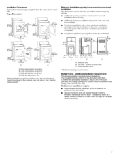
... required for mobile home installations. The installation must conform to the Manufactured Home Construction and Safety Standard, Title 24 CFR, Part 3280 (formerly the Federal Standard for the exhaust vent with a door, minimum ventilation openings in mobile homes to open fully. Installation Clearances The location must be large enough to allow the dryer door to introduce outside air into the dryer. Wide opening side-swing door C. Wide opening...
... required for mobile home installations. The installation must conform to the Manufactured Home Construction and Safety Standard, Title 24 CFR, Part 3280 (formerly the Federal Standard for the exhaust vent with a door, minimum ventilation openings in mobile homes to open fully. Installation Clearances The location must be large enough to allow the dryer door to introduce outside air into the dryer. Wide opening side-swing door C. Wide opening...

Installation Instructions
Page 4
... is installed in a location where grounding through the neutral conductor is prohibited. The 3-wire power supply cord, at least 4 ft (1.22 m) long, must have a proper outlet installed by providing a path of the terminal block. This dryer uses a cord having an equipment-grounding conductor and a grounding plug. Do not modify the plug on the power supply cord: if it here. [] This dryer is manufactured ready to install with a 3-wire electrical supply connection. The...
... is installed in a location where grounding through the neutral conductor is prohibited. The 3-wire power supply cord, at least 4 ft (1.22 m) long, must have a proper outlet installed by providing a path of the terminal block. This dryer uses a cord having an equipment-grounding conductor and a grounding plug. Do not modify the plug on the power supply cord: if it here. [] This dryer is manufactured ready to install with a 3-wire electrical supply connection. The...
Installation Instructions
Page 5
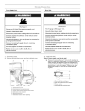
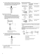
... or bare wire) must be connected to green ground connector. Power Supply Cord Direct Wire Fire Hazard Use a new UL listed 30 amp power supply cord. Securely tighten all electrical connections. Connect neutral wire (white or center wire) to center terminal (silver). Install strain relief. Tighten strain relief screws just enough to remaining 2 terminals (gold). Clamp section D. Failure to green ground connector. Disconnect power before making electrical connections. Securely tighten all electrical connections. Remove the hold...
... or bare wire) must be connected to green ground connector. Power Supply Cord Direct Wire Fire Hazard Use a new UL listed 30 amp power supply cord. Securely tighten all electrical connections. Connect neutral wire (white or center wire) to center terminal (silver). Install strain relief. Tighten strain relief screws just enough to remaining 2 terminals (gold). Clamp section D. Failure to green ground connector. Disconnect power before making electrical connections. Securely tighten all electrical connections. Remove the hold...
Installation Instructions
Page 6
... B. 4-prong plug C. Spade terminals with the dryer cabinet and be connecting to: Go to Section 4-wire receptacle (NEMA Type 14-30R) _.._ A UL listed, 120/240-volt 30-amp, dryer mpcooinrwdime* rumsu, pply 4-wire connection: Power supply cord 4-wire direct (12.7 ore) 3-wire receptacle (NEMA type 10-30R) A fused disconnect or cbiorcxu* it breaker A UL listed, 120/240-volt 30-amp, dryer mpcooinrwdime* rumsu, pply 4-wire connection: Direct Wire 3-wire connection: Power supply cord 3-wire direct A fused disconnect or box* circuit breaker 3-wire connection: Direct Wire *If local codes do...
... B. 4-prong plug C. Spade terminals with the dryer cabinet and be connecting to: Go to Section 4-wire receptacle (NEMA Type 14-30R) _.._ A UL listed, 120/240-volt 30-amp, dryer mpcooinrwdime* rumsu, pply 4-wire connection: Power supply cord 4-wire direct (12.7 ore) 3-wire receptacle (NEMA type 10-30R) A fused disconnect or cbiorcxu* it breaker A UL listed, 120/240-volt 30-amp, dryer mpcooinrwdime* rumsu, pply 4-wire connection: Direct Wire 3-wire connection: Power supply cord 3-wire direct A fused disconnect or box* circuit breaker 3-wire connection: Direct Wire *If local codes do...

Installation Instructions
Page 7
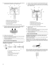
...-colored terminal block screw C. Direct wire cable must have completed your electrical connections. Center silver-colored terminal block screw C. Strip insulation back 1" (2.5 cm). Js D A. Secure cover with hold-down screw. 7. Ground wire (green or bare) of power supply cord to center silver-colored terminal block screw B. Squeeze hooked ends together. Remove neutral ground wire from end of extra length so dryer can be moved if needed. 1= Remove center silver-colored terminal block screw...
...-colored terminal block screw C. Direct wire cable must have completed your electrical connections. Center silver-colored terminal block screw C. Strip insulation back 1" (2.5 cm). Js D A. Secure cover with hold-down screw. 7. Ground wire (green or bare) of power supply cord to center silver-colored terminal block screw B. Squeeze hooked ends together. Remove neutral ground wire from end of extra length so dryer can be moved if needed. 1= Remove center silver-colored terminal block screw...
Installation Instructions
Page 8
... of extra length so dryer can be moved if needed. Direct wire cable must have 5 ft (1.52 m) of the terminal block (hook facing right), squeeze hooked end together and tighten screw, as shown. External ground conductor screw C. Ring terminals G, Neutral (white or center wire) When connecting to the center, silver-colored terminal screw of wires into slot of dryer rear panel. A B C F 1= Loosen or remove center silver-colored terminal block screw. 2. Tighten...
... of extra length so dryer can be moved if needed. Direct wire cable must have 5 ft (1.52 m) of the terminal block (hook facing right), squeeze hooked end together and tighten screw, as shown. External ground conductor screw C. Ring terminals G, Neutral (white or center wire) When connecting to the center, silver-colored terminal screw of wires into slot of dryer rear panel. A B C F 1= Loosen or remove center silver-colored terminal block screw. 2. Tighten...
Installation Instructions
Page 9
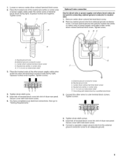
.... Connect neutral ground wire and the neutral wire (white or center wire) of power supply cord/cable under the center screw of the other wires to an adequate ground. Neutral wire (white or center wire) E, _" (1.9 cm) UL listed strain relief 3= Place the hooked ends of terminal block (hook facing right). Tighten strain relief screws. 5. Insert tab of terminal block cover into slot of dryer rear panel. Squeeze hooked end together. Remove neutral ground wire...
.... Connect neutral ground wire and the neutral wire (white or center wire) of power supply cord/cable under the center screw of the other wires to an adequate ground. Neutral wire (white or center wire) E, _" (1.9 cm) UL listed strain relief 3= Place the hooked ends of terminal block (hook facing right). Tighten strain relief screws. 5. Insert tab of terminal block cover into slot of dryer rear panel. Squeeze hooked end together. Remove neutral ground wire...
Installation Instructions
Page 10
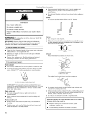
... acceptable only if accessible for cleaning. • Flexible metal vent must be purchased from the entire length of a building. Flexible metal vent • Flexible metal vents are shown here. Do not use duct tape. Exhaust hood must be in : [] Moisture damage to collect indoors, which may be fully extended and supported when the dryer is not plugged with lint. • Replace any gas vent, chimney, wall...
... acceptable only if accessible for cleaning. • Flexible metal vent must be purchased from the entire length of a building. Flexible metal vent • Flexible metal vents are shown here. Do not use duct tape. Exhaust hood must be in : [] Moisture damage to collect indoors, which may be fully extended and supported when the dryer is not plugged with lint. • Replace any gas vent, chimney, wall...
Installation Instructions
Page 11
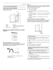
... vent C. Determine vent length and elbows needed for best drying performance • Use the Vent system chart below to determine type of the mobile home structure and must be securely fastened to a noncombustible portion of vent material and hood combinations acceptable to achieve the best drying performance. 11 B A .......... Please see the "Assistance or Service" section of the Dryer User Instructions. • Over-the-Top Installation: Part Number...
... vent C. Determine vent length and elbows needed for best drying performance • Use the Vent system chart below to determine type of the mobile home structure and must be securely fastened to a noncombustible portion of vent material and hood combinations acceptable to achieve the best drying performance. 11 B A .......... Please see the "Assistance or Service" section of the Dryer User Instructions. • Over-the-Top Installation: Part Number...

Installation Instructions
Page 12
... console panel). Avoid 90° turns. Reversible Large Side-Swing Door Excessive Weight Hazard Use two or more people to exhaust outlet in the flexible gas line. 4. Place cardboard under each of the dryer. Firmly grasp the body of the dryer. Remove bottom screws from the dryer carton. Slide the dryer on left -side opening around exhaust hood. 2. Using a 4" (10.2 cm) clamp, connect vent to move and install dryer. If connecting to...
... console panel). Avoid 90° turns. Reversible Large Side-Swing Door Excessive Weight Hazard Use two or more people to exhaust outlet in the flexible gas line. 4. Place cardboard under each of the dryer. Firmly grasp the body of the dryer. Remove bottom screws from the dryer carton. Slide the dryer on left -side opening around exhaust hood. 2. Using a 4" (10.2 cm) clamp, connect vent to move and install dryer. If connecting to...
Installation Instructions
Page 13
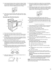
Remove door strike (E) from cabinet side of hinges. 3. Tighten screws halfway. Tighten screws. Reversible Super Wide Side-Swing Door B C E 1. Close door and check that door strike aligns with a damp cloth to see which step was skipped. 2. If there is an extra part, go away. 13 Be sure the vent is closed. 11. For direct wire installation, turn off screws. Read "Dryer Use" in hinges. 8. Wipe the dryer drum interior...
Remove door strike (E) from cabinet side of hinges. 3. Tighten screws halfway. Tighten screws. Reversible Super Wide Side-Swing Door B C E 1. Close door and check that door strike aligns with a damp cloth to see which step was skipped. 2. If there is an extra part, go away. 13 Be sure the vent is closed. 11. For direct wire installation, turn off screws. Read "Dryer Use" in hinges. 8. Wipe the dryer drum interior...
Parts Diagram
Page 1
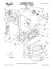
CABINET PARTS For Model: WED5500SQ0, WED5500ST0 (White) (Biscuit) 29"ELECTRIC DRYER 5−06 Litho in U.S.A. (LT.) 1 Part No. 8181353
CABINET PARTS For Model: WED5500SQ0, WED5500ST0 (White) (Biscuit) 29"ELECTRIC DRYER 5−06 Litho in U.S.A. (LT.) 1 Part No. 8181353
Parts Diagram
Page 2
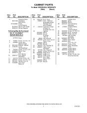
... x 5/8 (External Ground) 2 8181353 DESCRIPTION 1 Literature Parts 8577188 Installation Instructions W10042960 Sheet, Cycle Feature 8578183 Use & Care Guide 8528190 Wiring Diagram Following May Be Purchased DO−IT−YOURSELF REPAIR MANUALS 677818 Dryer 2 343641 Screw, 10−16 x 1/2 3 693995 Screw, Hex Washer Head 4 8541400 Bracket, Cabinet 5 3396795 Cover, Terminal Block 6 342043 Screw, 10−32 x 3/8 7 3396805 Panel, Rear 8 8546676 Clip, Door Spring 10 3406107 Door Switch Assembly 11 697773 Screw, 6−20 x 7/8 13...
... x 5/8 (External Ground) 2 8181353 DESCRIPTION 1 Literature Parts 8577188 Installation Instructions W10042960 Sheet, Cycle Feature 8578183 Use & Care Guide 8528190 Wiring Diagram Following May Be Purchased DO−IT−YOURSELF REPAIR MANUALS 677818 Dryer 2 343641 Screw, 10−16 x 1/2 3 693995 Screw, Hex Washer Head 4 8541400 Bracket, Cabinet 5 3396795 Cover, Terminal Block 6 342043 Screw, 10−32 x 3/8 7 3396805 Panel, Rear 8 8546676 Clip, Door Spring 10 3406107 Door Switch Assembly 11 697773 Screw, 6−20 x 7/8 13...

Parts Diagram
Page 3
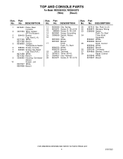
TOP AND CONSOLE PARTS For Model: WED5500SQ0, WED5500ST0 (White) (Biscuit) 8181353 3
TOP AND CONSOLE PARTS For Model: WED5500SQ0, WED5500ST0 (White) (Biscuit) 8181353 3
Parts Diagram
Page 4
... Screen, Lint 8557857 White 8557858 Biscuit Illus. Part No. DESCRIPTION Illus. No. Part No. No. TOP AND CONSOLE PARTS For Model: WED5500SQ0, WED5500ST0 (White) (Biscuit) Illus. DESCRIPTION 30 357213 Nut, Push−In (2) 32 8299873 Harness, Wiring 33 3398095 Switch, Push−To−Start 34 Timer Knob Assembly 8566061 White 8566064 Biscuit 35 Knob, Control 8565944 White 8565947 Biscuit 36 3936144 Connector...
... Screen, Lint 8557857 White 8557858 Biscuit Illus. Part No. DESCRIPTION Illus. No. Part No. No. TOP AND CONSOLE PARTS For Model: WED5500SQ0, WED5500ST0 (White) (Biscuit) Illus. DESCRIPTION 30 357213 Nut, Push−In (2) 32 8299873 Harness, Wiring 33 3398095 Switch, Push−To−Start 34 Timer Knob Assembly 8566061 White 8566064 Biscuit 35 Knob, Control 8565944 White 8565947 Biscuit 36 3936144 Connector...

Parts Diagram
Page 5
... C) 16 3977373 Bracket, Drum Light 17 8565582 Element, Heater 18 3403634 Socket Assembly 19 279457 Wire Kit, Terminal (For Heater Element Wiring Harness Repair) 20 3406124 Bulb, Light 21 3402841 Lens, Drum Light 23 487909 Screw, 8−15 x 1/2 24 8066086 Drum Hole Plug Illus. DESCRIPTION 25 3390647 Screw, 8−18 x 1/2 41 690997 Ring, Tri 42 3399506 Shaft, L.H. 43 3399507 Shaft, R.H. 44 3397590 Roller, Support 46 348197 Washer, Support 47 3359452 Nut...
... C) 16 3977373 Bracket, Drum Light 17 8565582 Element, Heater 18 3403634 Socket Assembly 19 279457 Wire Kit, Terminal (For Heater Element Wiring Harness Repair) 20 3406124 Bulb, Light 21 3402841 Lens, Drum Light 23 487909 Screw, 8−15 x 1/2 24 8066086 Drum Hole Plug Illus. DESCRIPTION 25 3390647 Screw, 8−18 x 1/2 41 690997 Ring, Tri 42 3399506 Shaft, L.H. 43 3399507 Shaft, R.H. 44 3397590 Roller, Support 46 348197 Washer, Support 47 3359452 Nut...
Parts Diagram
Page 6
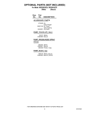
DESCRIPTION ACCESSORY PARTS 279948 Kit, Dryer Repair 8522199 Kit, Dryer Vent Testing 3404351 Dry Rack PAINT, TOUCH−UP (1/2oz.) 72017 White 4392899 Biscuit PAINT, PRESSURIZED SPRAY (12 oz.) 350930 White 4392901 Biscuit 350938 Primer, Gray PAINT, BULK (1 qt.) 799344 White (Uncut) 4392900 Biscuit (Uncut) 6 8181353 Part No. OPTIONAL PARTS (NOT INCLUDED) For Model: WED5500SQ0, WED5500ST0 (White) (Biscuit) Illus. No.
DESCRIPTION ACCESSORY PARTS 279948 Kit, Dryer Repair 8522199 Kit, Dryer Vent Testing 3404351 Dry Rack PAINT, TOUCH−UP (1/2oz.) 72017 White 4392899 Biscuit PAINT, PRESSURIZED SPRAY (12 oz.) 350930 White 4392901 Biscuit 350938 Primer, Gray PAINT, BULK (1 qt.) 799344 White (Uncut) 4392900 Biscuit (Uncut) 6 8181353 Part No. OPTIONAL PARTS (NOT INCLUDED) For Model: WED5500SQ0, WED5500ST0 (White) (Biscuit) Illus. No.


