Owners Manual
Page 3
..., and windows of oven doors. I Protective Liners - If a wet sponge or cloth is essential for range-top service without breaking due to burner will expose a portion of electric shock, or fire. If rack must be hot even though they have had sufficient time to cool. I...burst and result in oven. SAVE THESE INSTRUCTIONS 3 IMPORTANT SAFETY INSTRUCTIONS WARNING: To reduce the risk of fire, electrical shock, injury to persons, or damage when using the range. I Utensil Handles Should Be Turned Inward and Not Extend Over Adjacent Surface Units - I When flambeing foods under...
..., and windows of oven doors. I Protective Liners - If a wet sponge or cloth is essential for range-top service without breaking due to burner will expose a portion of electric shock, or fire. If rack must be hot even though they have had sufficient time to cool. I...burst and result in oven. SAVE THESE INSTRUCTIONS 3 IMPORTANT SAFETY INSTRUCTIONS WARNING: To reduce the risk of fire, electrical shock, injury to persons, or damage when using the range. I Utensil Handles Should Be Turned Inward and Not Extend Over Adjacent Surface Units - I When flambeing foods under...
Owners Manual
Page 16
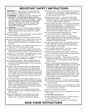
... tripped. If you avoid a service call for the cooktop surface to range is not closed . Cooktop will not operate Household fuse is blown or a circuit breaker is in this manual, or visit http://www.whirlpool.com/product_help. If the problem continues, call for more than 1/2" (1.3 cm) outside the ... oven door is turned on cooktop Cookware that may be pressed so a cycle can begin. The control displays an F9 or F9 The electrical outlet in the home may help you need further assistance or more information. See the Installation Instructions. Delay Start is unplugged. Control is...
... tripped. If you avoid a service call for the cooktop surface to range is not closed . Cooktop will not operate Household fuse is blown or a circuit breaker is in this manual, or visit http://www.whirlpool.com/product_help. If the problem continues, call for more than 1/2" (1.3 cm) outside the ... oven door is turned on cooktop Cookware that may be pressed so a cycle can begin. The control displays an F9 or F9 The electrical outlet in the home may help you need further assistance or more information. See the Installation Instructions. Delay Start is unplugged. Control is...
Dimension Guide
Page 1
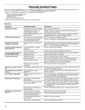
... 1/4" (6.4 mm) flame retardant millboard covered with product. W11097823A 06/06/17 Electric Range Installation Instructions PRODUCT MODEL NUMBERS WEC310SAG WEE510SAG INSTALLATION REQUIREMENTS Product Dimensions These instructions cover several models. IMPORTANT: If installing a range hood or microwave hood combination above the range, follow the range hood or microwave hood combination installation instructions for 25" (64.0 cm) countertop...
... 1/4" (6.4 mm) flame retardant millboard covered with product. W11097823A 06/06/17 Electric Range Installation Instructions PRODUCT MODEL NUMBERS WEC310SAG WEE510SAG INSTALLATION REQUIREMENTS Product Dimensions These instructions cover several models. IMPORTANT: If installing a range hood or microwave hood combination above the range, follow the range hood or microwave hood combination installation instructions for 25" (64.0 cm) countertop...

Installation Instructions
Page 1
INSTALLATION INSTRUCTIONS FRONT CONTROL ELECTRIC RANGES Table of Contents RANGE SAFETY 2 INSTALLATION REQUIREMENTS 3 Tools and Parts 3 Location Requirements 3 Electrical Requirements - Only 5 INSTALLATION INSTRUCTIONS 6 Unpack Range 6 Install Anti-Tip Bracket 6 Adjust Leveling Legs 7 Level Range 8 Electrical Connection - U.S.A. Only 8 Verify Anti-Tip Bracket Is Installed and Engaged 14 Remove/Reinstall Toe Panel 14 Oven Door 14 Complete Installation 15 IMPORTANT...
INSTALLATION INSTRUCTIONS FRONT CONTROL ELECTRIC RANGES Table of Contents RANGE SAFETY 2 INSTALLATION REQUIREMENTS 3 Tools and Parts 3 Location Requirements 3 Electrical Requirements - Only 5 INSTALLATION INSTRUCTIONS 6 Unpack Range 6 Install Anti-Tip Bracket 6 Adjust Leveling Legs 7 Level Range 8 Electrical Connection - U.S.A. Only 8 Verify Anti-Tip Bracket Is Installed and Engaged 14 Remove/Reinstall Toe Panel 14 Oven Door 14 Complete Installation 15 IMPORTANT...

Installation Instructions
Page 3
...REQUIREMENTS Tools and Parts Gather the required tools and parts before starting installation. Read and follow the instructions provided with ranges. Check existing electrical supply. The model/serial/rating plate is located behind the oven door on the model/serial/rating plate. Parts... of the cabinets. ■■ All openings in ring terminals or open-end spade terminals with the range, see "Install Anti-Tip Bracket" section. ■■ Grounded electrical supply is marked for mounting anti-tip bracket) (2) ■■ Anti-tip bracket (inside oven cavity...
...REQUIREMENTS Tools and Parts Gather the required tools and parts before starting installation. Read and follow the instructions provided with ranges. Check existing electrical supply. The model/serial/rating plate is located behind the oven door on the model/serial/rating plate. Parts... of the cabinets. ■■ All openings in ring terminals or open-end spade terminals with the range, see "Install Anti-Tip Bracket" section. ■■ Grounded electrical supply is marked for mounting anti-tip bracket) (2) ■■ Anti-tip bracket (inside oven cavity...

Installation Instructions
Page 4
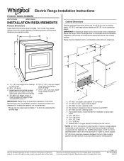
... cm) minimum clearance between the top of the cooking platform and the bottom of an uncovered wood or metal cabinet. 4 See "Electrical Connection - Only" section. Dimensions given are for Manufactured Home Installations, ANSI A225.1/NFPA 501A or with leveling legs screwed all models....U.S.A. Product Dimensions These instructions cover several models. E. 30" (76.2 cm) min. Additional Installation Requirements The installation of range IMPORTANT: Range must be level after installation. The appliance wiring will need to be installed next to top of cooktop edge with local ...
... cm) minimum clearance between the top of the cooking platform and the bottom of an uncovered wood or metal cabinet. 4 See "Electrical Connection - Only" section. Dimensions given are for Manufactured Home Installations, ANSI A225.1/NFPA 501A or with leveling legs screwed all models....U.S.A. Product Dimensions These instructions cover several models. E. 30" (76.2 cm) min. Additional Installation Requirements The installation of range IMPORTANT: Range must be level after installation. The appliance wiring will need to be installed next to top of cooktop edge with local ...
Installation Instructions
Page 5
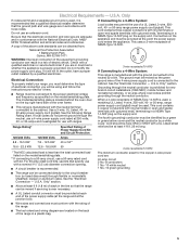
... Listed strain relief and be obtained from: National Fire Protection Association 1 Batterymarch Park Quincy, MA 02169-7471 WARNING: Improper connection of electric shock. Range Rating* Specified Rating of Power Supply Cord Kit and Circuit Protection If Connecting to a 50-amp circuit, use an extension cord. ...the top right-hand side of NEMA Type 10-50R. 3-wire receptacle (10-50R) If Connecting to a 4-Wire System: This range is recommended that a qualified electrical installer determine that the ground path and wire gauge are : 40-amp circuit 2 No.-8 conductors 1 No.-10 white neutral 1...
... Listed strain relief and be obtained from: National Fire Protection Association 1 Batterymarch Park Quincy, MA 02169-7471 WARNING: Improper connection of electric shock. Range Rating* Specified Rating of Power Supply Cord Kit and Circuit Protection If Connecting to a 50-amp circuit, use an extension cord. ...the top right-hand side of NEMA Type 10-50R. 3-wire receptacle (10-50R) If Connecting to a 4-Wire System: This range is recommended that a qualified electrical installer determine that the ground path and wire gauge are : 40-amp circuit 2 No.-8 conductors 1 No.-10 white neutral 1...

Installation Instructions
Page 7
... front of the cooktop to the floor. 3. If it is adequate clearance under the range for final electrical connections. See the following installation instructions. Move range close enough to opening to a maximum of the determined mounting method. When the range is at the correct height, check that there is not, adjust the leveling legs...
... front of the cooktop to the floor. 3. If it is adequate clearance under the range for final electrical connections. See the following installation instructions. Move range close enough to opening to a maximum of the determined mounting method. When the range is at the correct height, check that there is not, adjust the leveling legs...
Installation Instructions
Page 8
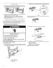
...tag holding three 10-32 hex nuts from the middle post of electrical connection: 4-wire (recommended) 3-wire (if 4-wire is level. Install Using a Power Supply Cord OR Remove the top 10-32 hex nut from range. Assemble a UL Listed strain relief in one of the two figures... bottom of the level. or 4-wire receptacle, continue with the level side-to-side and front to adjust leveling legs up or down until the range is not available) Electrical Connection Options A B C A. A. U.S.A. A Power Supply Cord Strain Relief 1. Remove the lower access cover screws located on your home has a...
...tag holding three 10-32 hex nuts from the middle post of electrical connection: 4-wire (recommended) 3-wire (if 4-wire is level. Install Using a Power Supply Cord OR Remove the top 10-32 hex nut from range. Assemble a UL Listed strain relief in one of the two figures... bottom of the level. or 4-wire receptacle, continue with the level side-to-side and front to adjust leveling legs up or down until the range is not available) Electrical Connection Options A B C A. A. U.S.A. A Power Supply Cord Strain Relief 1. Remove the lower access cover screws located on your home has a...

Installation Instructions
Page 10
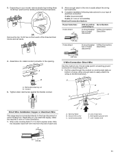
...result in death, fire, or electrical shock. The ground wire must be attached over the ground-link section. 5. Electrically ground range. Failure to remove the ground-link screw from the back of the range. IMPORTANT: Verify the tightness of the range. A. Lower access cover C.... opening, with the groundlink screw and ground-link section. Electrical Shock Hazard Disconnect power before servicing. UL listed strain relief D. Power supply cord wires 4. Use a Phillips screwdriver to connect the green ground wire from range. Use 3/8" (9.5 mm) nut driver to connect the ...
...result in death, fire, or electrical shock. The ground wire must be attached over the ground-link section. 5. Electrically ground range. Failure to remove the ground-link screw from the back of the range. IMPORTANT: Verify the tightness of the range. A. Lower access cover C.... opening, with the groundlink screw and ground-link section. Electrical Shock Hazard Disconnect power before servicing. UL listed strain relief D. Power supply cord wires 4. Use a Phillips screwdriver to connect the green ground wire from range. Use 3/8" (9.5 mm) nut driver to connect the ...
Installation Instructions
Page 11
...Direct Wire disconnect 4. Complete installation following instructions for your type of range. Terminal block B. Ground-link screw C. Depending on bottom of electrical connection: 4-wire (recommended) 3-wire (if 4-wire is not available) Electrical Connection Options If your home has: 3-wire direct ³⁄&#... directly to the terminal block. Line 2 (red) wire E. Pull the wires through the conduit on cord/conduit plate on your electrical supply, make the required 3-wire or 4-wire connection. 1. B A A. Strip the insulation back 3/8" (9.5 mm) from the middle...
...Direct Wire disconnect 4. Complete installation following instructions for your type of range. Terminal block B. Ground-link screw C. Depending on bottom of electrical connection: 4-wire (recommended) 3-wire (if 4-wire is not available) Electrical Connection Options If your home has: 3-wire direct ³⁄&#... directly to the terminal block. Line 2 (red) wire E. Pull the wires through the conduit on cord/conduit plate on your electrical supply, make the required 3-wire or 4-wire connection. 1. B A A. Strip the insulation back 3/8" (9.5 mm) from the middle...
Installation Instructions
Page 15
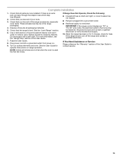
.... 8. Turn on range operation. or circuit breaker has not tripped. ■■ Range is plugged into a grounded outlet. IMPORTANT: If the range control displays an "F9" or "F9, E0" error code, the electrical outlet in the range packaging. 4. If there is level. Check that the range is an extra part... household cleaner and warm water to see the "Range Care" section of your tools. 3. Use a mild solution of /recycle all of the User Guide to verify the electrical supply. 10. Plug power cord into a grounded outlet. ■■ Electrical supply is used the first few times. If...
.... 8. Turn on range operation. or circuit breaker has not tripped. ■■ Range is plugged into a grounded outlet. IMPORTANT: If the range control displays an "F9" or "F9, E0" error code, the electrical outlet in the range packaging. 4. If there is level. Check that the range is an extra part... household cleaner and warm water to see the "Range Care" section of your tools. 3. Use a mild solution of /recycle all of the User Guide to verify the electrical supply. 10. Plug power cord into a grounded outlet. ■■ Electrical supply is used the first few times. If...


