
Installation Guide
Page 1
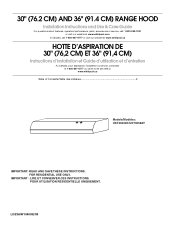
....4 CM) RANGE HOOD Installation Instructions and Use & Care Guide For questions about features, operation/performance, parts, accessories or service, call: 1-800-253-1301 or visit our website at www.whirlpool.com In Canada, call 1-800-807-6777 or visit our website at www.whirlpool.ca HOTTE D'ASPIRATION DE 30" (76,2 CM) ET 36" (91,4 CM) Instructions d'installation et Guide d'utilisation et d'entretien Au Canada, pour assistance, installation ou service, composer le...
....4 CM) RANGE HOOD Installation Instructions and Use & Care Guide For questions about features, operation/performance, parts, accessories or service, call: 1-800-253-1301 or visit our website at www.whirlpool.com In Canada, call 1-800-807-6777 or visit our website at www.whirlpool.ca HOTTE D'ASPIRATION DE 30" (76,2 CM) ET 36" (91,4 CM) Instructions d'installation et Guide d'utilisation et d'entretien Au Canada, pour assistance, installation ou service, composer le...
Installation Guide
Page 2
...We have provided many important safety messages in this manual and on your appliance. TABLE OF CONTENTS RANGE HOOD SAFETY 2 INSTALLATION REQUIREMENTS 4 Tools and Parts 4 Location Requirements 4 Venting Requirements 5 Electrical Requirements 6 INSTALLATION INSTRUCTIONS 7 Prepare Location 7 Install Range Hood 8 Make Electrical Connection 10 Complete Installation 10 RANGE HOOD USE 11 Range Hood Controls 11 RANGE HOOD CARE 11 Cleaning 11 WIRING DIAGRAM 12 ASSISTANCE OR SERVICE 13 In the U.S.A 13 In Canada 13 Accessories 13 WARRANTY 14 TABLE DES MATIÈRES SÉCURITÉ...
...We have provided many important safety messages in this manual and on your appliance. TABLE OF CONTENTS RANGE HOOD SAFETY 2 INSTALLATION REQUIREMENTS 4 Tools and Parts 4 Location Requirements 4 Venting Requirements 5 Electrical Requirements 6 INSTALLATION INSTRUCTIONS 7 Prepare Location 7 Install Range Hood 8 Make Electrical Connection 10 Complete Installation 10 RANGE HOOD USE 11 Range Hood Controls 11 RANGE HOOD CARE 11 Cleaning 11 WIRING DIAGRAM 12 ASSISTANCE OR SERVICE 13 In the U.S.A 13 In Canada 13 Accessories 13 WARRANTY 14 TABLE DES MATIÈRES SÉCURITÉ...
Installation Guide
Page 3
... speed control device. WARNING: TO REDUCE THE RISK OF INJURY TO PERSONS IN THE EVENT OF A RANGE TOP GREASE FIRE, OBSERVE THE FOLLOWING:a ■ SMOTHER FLAMES with a close fitting lid, cookie sheet, or metal tray, then turn hood ON when cooking at service panel and lock the service disconnecting means to the service panel. ■ Installation work and electrical wiring must always be sure to duct air outside - When the service...
... speed control device. WARNING: TO REDUCE THE RISK OF INJURY TO PERSONS IN THE EVENT OF A RANGE TOP GREASE FIRE, OBSERVE THE FOLLOWING:a ■ SMOTHER FLAMES with a close fitting lid, cookie sheet, or metal tray, then turn hood ON when cooking at service panel and lock the service disconnecting means to the service panel. ■ Installation work and electrical wiring must always be sure to duct air outside - When the service...
Installation Guide
Page 4
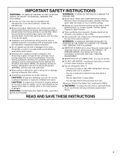
... model/serial rating plate. Tools needed ■ 3¹⁄₄" x 10" (8.3 x 25.4 cm) rectangular metal vent system ■ Wall or roof cap with recessed bottoms: ■ Two 2" (5.1 cm) wide filler strips. Length and thickness determined by recess dimensions. ■ Four flat head wood screws or machine screws with any cutouts. ■ Grounded electrical outlet is the installer's responsibility to attach filler strips). Consult the cooktop/range manufacturer installation instructions before starting installation. See "Electrical Requirements...
... model/serial rating plate. Tools needed ■ 3¹⁄₄" x 10" (8.3 x 25.4 cm) rectangular metal vent system ■ Wall or roof cap with recessed bottoms: ■ Two 2" (5.1 cm) wide filler strips. Length and thickness determined by recess dimensions. ■ Four flat head wood screws or machine screws with any cutouts. ■ Grounded electrical outlet is the installer's responsibility to attach filler strips). Consult the cooktop/range manufacturer installation instructions before starting installation. See "Electrical Requirements...
Installation Guide
Page 5
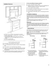
... use of makeup air systems when using ventilation systems greater than 1 elbow is not recommended. ■ The length of vent system and number of range hood to provide efficient performance. Cold Weather Installations An additional back draft damper should be installed to minimize backward cold air flow and a thermal break should be installed to 24" (61.0 cm) max. Wall cap with a maximum vent length of the thermal break. above the cooking...
... use of makeup air systems when using ventilation systems greater than 1 elbow is not recommended. ■ The length of vent system and number of range hood to provide efficient performance. Cold Weather Installations An additional back draft damper should be installed to minimize backward cold air flow and a thermal break should be installed to 24" (61.0 cm) max. Wall cap with a maximum vent length of the thermal break. above the cooking...
Installation Guide
Page 6
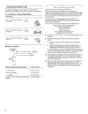
... behind the filter on the model/serial rating plate. Connect the aluminum wiring to the added section of 3¹⁄₄" x 10" (8.3 cm x 25.4 cm) system = 5.0 ft (1.5 m) = 8.0 ft (2.4 m) = 0.0 ft (0.0 m) = 13.0 ft (3.9 m) Electrical Requirements Observe all governing codes and ordinances. wall cap Length of copper wire using special connectors and/or tools designed and UL listed for each vent piece used , it is recommended that a qualified electrician determine that the electrical installation is...
... behind the filter on the model/serial rating plate. Connect the aluminum wiring to the added section of 3¹⁄₄" x 10" (8.3 cm x 25.4 cm) system = 5.0 ft (1.5 m) = 8.0 ft (2.4 m) = 0.0 ft (0.0 m) = 13.0 ft (3.9 m) Electrical Requirements Observe all governing codes and ordinances. wall cap Length of copper wire using special connectors and/or tools designed and UL listed for each vent piece used , it is recommended that a qualified electrician determine that the electrical installation is...
Installation Guide
Page 7
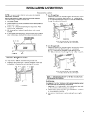
... the cabinet. Disconnect power. Select a flat surface for 36" (91.4 cm) models Cabinet bottom 3" (7.6 cm) Wall To wire through the rear wall at this point. A ⁷⁄₈" (2.2 cm) from wall, not cabinet frame 3" (7.6 cm) Wood filler strips (recessed cabinet bottoms only) Centerline A. 8³⁄₈" (21.3 cm) for 30" (76.2 cm) models 11³⁄₈" (28.9 cm) for assembling the range hood. Cut Openings for exhaust vent. 1. INSTALLATION INSTRUCTIONS...
... the cabinet. Disconnect power. Select a flat surface for 36" (91.4 cm) models Cabinet bottom 3" (7.6 cm) Wall To wire through the rear wall at this point. A ⁷⁄₈" (2.2 cm) from wall, not cabinet frame 3" (7.6 cm) Wood filler strips (recessed cabinet bottoms only) Centerline A. 8³⁄₈" (21.3 cm) for 30" (76.2 cm) models 11³⁄₈" (28.9 cm) for assembling the range hood. Cut Openings for exhaust vent. 1. INSTALLATION INSTRUCTIONS...
Installation Guide
Page 8
... wall. 3. Use saber or keyhole saw to Round Vent Transition Roof Venting To make a 3½" x 10½" (8.9 cm x 26.7 cm) rectangle in upper cabinet or wall. See "Venting Requirements" section. 2. Use caulking to the selected venting method. To make a circular vent opening *5" (12.7 cm) Cabinet cutouts *From wall, not cabinet frame Install Vent System 1. Remove the 3¼" x 10" (8.3 x 25.4 cm) rectangular vent connector attached with a diameter that is ¼" (0.64 cm) larger than the vent. 4. Use these screws...
... wall. 3. Use saber or keyhole saw to Round Vent Transition Roof Venting To make a 3½" x 10½" (8.9 cm x 26.7 cm) rectangle in upper cabinet or wall. See "Venting Requirements" section. 2. Use caulking to the selected venting method. To make a circular vent opening *5" (12.7 cm) Cabinet cutouts *From wall, not cabinet frame Install Vent System 1. Remove the 3¼" x 10" (8.3 x 25.4 cm) rectangular vent connector attached with a diameter that is ¼" (0.64 cm) larger than the vent. 4. Use these screws...
Installation Guide
Page 9
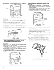
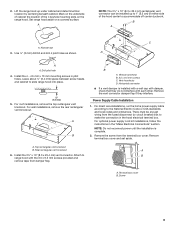
... is installed with a wall cap with damper, check that they interfere. Attach to the National Electric Code or CSA standards and local codes and ordinances. Screw 9 D A A. Vertical connector B. 3.5 x 9.5 mm screws C. Power Supply Cable Installation 1. For optional power supply cord kit installations, follow the instructions in pilot holes. Remove terminal box cover and set aside. Rear rectangular vent knockout A 6. Horizontal connector ■ If a vent damper is complete. 2. For direct wire installations, run the home power supply cable according to B range hood...
... is installed with a wall cap with damper, check that they interfere. Attach to the National Electric Code or CSA standards and local codes and ordinances. Screw 9 D A A. Vertical connector B. 3.5 x 9.5 mm screws C. Power Supply Cable Installation 1. For optional power supply cord kit installations, follow the instructions in pilot holes. Remove terminal box cover and set aside. Rear rectangular vent knockout A 6. Horizontal connector ■ If a vent damper is complete. 2. For direct wire installations, run the home power supply cable according to B range hood...
Installation Guide
Page 10
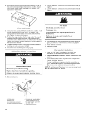
... wire E. Use UL listed wire connectors and connect black wires (B) together. Position the range hood so that the large end of the range hood fan and light. Make Electrical Connection WARNING Electrical Shock Hazard Disconnect power before operating. Replace all parts and panels before servicing. Use copper wire. Complete Installation 1. See "Replacing the Incandescent Light Bulb" section. 2. Seal joints with vent clamps or duct tape to do so can result in death, fire, or electrical shock. 4. Failure to make connections in terminal box. Fire Hazard Electrically...
... wire E. Use UL listed wire connectors and connect black wires (B) together. Position the range hood so that the large end of the range hood fan and light. Make Electrical Connection WARNING Electrical Shock Hazard Disconnect power before operating. Replace all parts and panels before servicing. Use copper wire. Complete Installation 1. See "Replacing the Incandescent Light Bulb" section. 2. Seal joints with vent clamps or duct tape to do so can result in death, fire, or electrical shock. 4. Failure to make connections in terminal box. Fire Hazard Electrically...
Installation Guide
Page 11
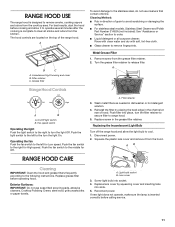
... cooking is designed to remove smoke, cooking vapors and odors from the hood. Reconnect power. Metal Grease Filter 1. Turn the grease filter retainer to the following instructions. Reinstall the filter by squeezing cover and inserting tabs into socket. 4. Replacing the Incandescent Light Bulb Turn off the range hood and allow it from the cooktop area. Replace grease filter before operating hood. Replace screw in the channel at rear of hood. Screw light bulb into slots. 5. A. Wash metal filters as needed in direction of the range hood. RANGE HOOD USE The range hood...
... cooking is designed to remove smoke, cooking vapors and odors from the hood. Reconnect power. Metal Grease Filter 1. Turn the grease filter retainer to the following instructions. Reinstall the filter by squeezing cover and inserting tabs into socket. 4. Replacing the Incandescent Light Bulb Turn off the range hood and allow it from the cooktop area. Replace grease filter before operating hood. Replace screw in the channel at rear of hood. Screw light bulb into slots. 5. A. Wash metal filters as needed in direction of the range hood. RANGE HOOD USE The range hood...
Installation Guide
Page 12
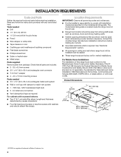
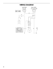
Off - High SE116B BK BK W R BK BR R W BR Speed 1 Common Speed 2 R W BK Motor Characteristics Power Supply Frequency Amperage 120 VAC 60 Hz 0.9 ±10% A Wattage Rating 50 ±10% Watts Motor Resistance White - Red 22.3 ±10% Ohms White - Black 13.4 ±10% Ohms N W W BK Ground Screw C19 L GND 12 Off Motor Switch Low - WIRING DIAGRAM Light Switch On -
Off - High SE116B BK BK W R BK BR R W BR Speed 1 Common Speed 2 R W BK Motor Characteristics Power Supply Frequency Amperage 120 VAC 60 Hz 0.9 ±10% A Wattage Rating 50 ±10% Watts Motor Resistance White - Red 22.3 ±10% Ohms White - Black 13.4 ±10% Ohms N W W BK Ground Screw C19 L GND 12 Off Motor Switch Low - WIRING DIAGRAM Light Switch On -
Installation Guide
Page 13
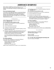
..., repair parts distributors, and service companies. Call the Whirlpool Customer eXperience Center toll free: 1-800-253-1301. Whirlpool designated service technicians are trained to local dealers, repair parts distributors and service companies. In the U.S.A. If you need replacement parts If you need further assistance, you can write to Whirlpool Canada LP with : ■ Features and specifications on our full line of appliances. ■ Installation information. ■ Use and maintenance procedures. ■ Accessory...
..., repair parts distributors, and service companies. Call the Whirlpool Customer eXperience Center toll free: 1-800-253-1301. Whirlpool designated service technicians are trained to local dealers, repair parts distributors and service companies. In the U.S.A. If you need replacement parts If you need further assistance, you can write to Whirlpool Canada LP with : ■ Features and specifications on our full line of appliances. ■ Installation information. ■ Use and maintenance procedures. ■ Accessory...
Installation Guide
Page 14
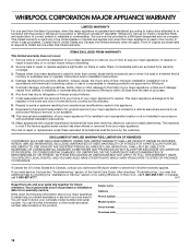
... to use of purchase or installation date for future reference. ITEMS EXCLUDED FROM WARRANTY This limited warranty does not cover: 1. Service calls to refrigerator or freezer product failures. 7. Major appliances with the removal from your home of your complete model number and serial number. Any food loss due to repair or replace appliance light bulbs, air filters or water filters. DISCLAIMER OF IMPLIED WARRANTIES; This warranty is covered by Whirlpool. 5. LIMITATION OF REMEDIES CUSTOMER'S SOLE...
... to use of purchase or installation date for future reference. ITEMS EXCLUDED FROM WARRANTY This limited warranty does not cover: 1. Service calls to refrigerator or freezer product failures. 7. Major appliances with the removal from your home of your complete model number and serial number. Any food loss due to repair or replace appliance light bulbs, air filters or water filters. DISCLAIMER OF IMPLIED WARRANTIES; This warranty is covered by Whirlpool. 5. LIMITATION OF REMEDIES CUSTOMER'S SOLE...

Warranty Information
Page 1
... checking "Troubleshooting," you may find this book and your major appliance to better help by checking the "Assistance or Service" section or by the customer. Dealer name Address Phone number Model number Serial number Purchase date 14 Any food loss due to repair or replace appliance light bulbs, air filters or water filters. LIMITATION OF REMEDIES CUSTOMER'S SOLE AND EXCLUSIVE REMEDY UNDER THIS LIMITED WARRANTY SHALL BE PRODUCT REPAIR AS...
... checking "Troubleshooting," you may find this book and your major appliance to better help by checking the "Assistance or Service" section or by the customer. Dealer name Address Phone number Model number Serial number Purchase date 14 Any food loss due to repair or replace appliance light bulbs, air filters or water filters. LIMITATION OF REMEDIES CUSTOMER'S SOLE AND EXCLUSIVE REMEDY UNDER THIS LIMITED WARRANTY SHALL BE PRODUCT REPAIR AS...


