
Installation Guide
Page 2
... You can be killed or seriously injured if you don't follow instructions. TABLE OF CONTENTS RANGE HOOD SAFETY 2 INSTALLATION REQUIREMENTS 4 Tools and Parts 4 Location Requirements 4 Venting Requirements 5 Electrical Requirements 6 INSTALLATION INSTRUCTIONS 7 Prepare Location 7 Install Range Hood 8 Make Electrical Connection 9 Complete Installation 10 RANGE HOOD USE 10 Range Hood Controls 10 RANGE HOOD CARE 11 Cleaning 11 WIRING DIAGRAM 12 ASSISTANCE OR SERVICE 13 In the U.S.A 13 In Canada 13 Accessories 13 WARRANTY 14 TABLE DES MATIÈRES SÉCURITÉ DE LA...
... You can be killed or seriously injured if you don't follow instructions. TABLE OF CONTENTS RANGE HOOD SAFETY 2 INSTALLATION REQUIREMENTS 4 Tools and Parts 4 Location Requirements 4 Venting Requirements 5 Electrical Requirements 6 INSTALLATION INSTRUCTIONS 7 Prepare Location 7 Install Range Hood 8 Make Electrical Connection 9 Complete Installation 10 RANGE HOOD USE 10 Range Hood Controls 10 RANGE HOOD CARE 11 Cleaning 11 WIRING DIAGRAM 12 ASSISTANCE OR SERVICE 13 In the U.S.A 13 In Canada 13 Accessories 13 WARRANTY 14 TABLE DES MATIÈRES SÉCURITÉ DE LA...

Installation Guide
Page 3
...;). ■ Clean ventilating fans frequently. BE CAREFUL TO PREVENT BURNS. You can fight the fire with your back to the service panel. ■ Installation work and electrical wiring must always be sure to prevent backdrafting. aBased on fan or filter. ■ Use proper pan size. CAUTION: To reduce risk of fire or electrical shock, do not vent exhaust air into spaces within walls or ceilings, attics or into wall or ceiling; WARNING: TO...
...;). ■ Clean ventilating fans frequently. BE CAREFUL TO PREVENT BURNS. You can fight the fire with your back to the service panel. ■ Installation work and electrical wiring must always be sure to prevent backdrafting. aBased on fan or filter. ■ Use proper pan size. CAUTION: To reduce risk of fire or electrical shock, do not vent exhaust air into spaces within walls or ceilings, attics or into wall or ceiling; WARNING: TO...

Installation Guide
Page 4
... Parts Gather the required tools and parts before making any tools listed here. For Mobile Home Installations The installation of this range hood must be away from package. Length and thickness determined by recess dimensions. ■ Four flat head wood screws or machine screws with recessed bottoms: ■ Two 2" (5.1 cm) wide filler strips. The model/serial rating plate is located inside the range hood on the model/serial rating plate. Read and follow the instructions...
... Parts Gather the required tools and parts before making any tools listed here. For Mobile Home Installations The installation of this range hood must be away from package. Length and thickness determined by recess dimensions. ■ Four flat head wood screws or machine screws with recessed bottoms: ■ Two 2" (5.1 cm) wide filler strips. The model/serial rating plate is located inside the range hood on the model/serial rating plate. Read and follow the instructions...
Installation Guide
Page 5
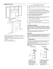
... install 2 elbows together. ■ Use clamps or duct tape to seal all joints in the vent system. ■ The vent system must terminate to where the vent system enters the heated portion of range hood to seal exterior wall or roof opening width for 30" (76.2 cm) models and 36" (91.4 cm) min. Makeup Air Local building codes may require the use a 4" (10.2 cm) laundry-type wall cap. ■ Use...
... install 2 elbows together. ■ Use clamps or duct tape to seal all joints in the vent system. ■ The vent system must terminate to where the vent system enters the heated portion of range hood to seal exterior wall or roof opening width for 30" (76.2 cm) models and 36" (91.4 cm) min. Makeup Air Local building codes may require the use a 4" (10.2 cm) laundry-type wall cap. ■ Use...

Installation Guide
Page 6
...; elbow 1 - Follow the electrical connector manufacturer's recommended procedure. Connect the aluminum wiring to the added section of copper wire using special connectors and/or tools designed and UL listed for each vent piece used , it is recommended that a qualified electrician determine that the electrical installation is used in conformance with the rating of the appliance as specified on the rear wall of the range hood. ■ Wire sizes must conform with National Electrical Code...
...; elbow 1 - Follow the electrical connector manufacturer's recommended procedure. Connect the aluminum wiring to the added section of copper wire using special connectors and/or tools designed and UL listed for each vent piece used , it is recommended that a qualified electrician determine that the electrical installation is used in conformance with the rating of the appliance as specified on the rear wall of the range hood. ■ Wire sizes must conform with National Electrical Code...
Installation Guide
Page 7
...³⁄₈" (28.9 cm) for exhaust vent. 1. Mark a line distance "A" from the back wall on your model, determine which venting method to attach filler strips in the area the vent opening will be installed before hood is installed. Drill a 1¼" (3.2 cm) diameter hole through top: 1. Lift the range hood and set it upside down onto covered surface. 5. INSTALLATION INSTRUCTIONS Prepare Location NOTE: It is recommended...
...³⁄₈" (28.9 cm) for exhaust vent. 1. Mark a line distance "A" from the back wall on your model, determine which venting method to attach filler strips in the area the vent opening will be installed before hood is installed. Drill a 1¼" (3.2 cm) diameter hole through top: 1. Lift the range hood and set it upside down onto covered surface. 5. INSTALLATION INSTRUCTIONS Prepare Location NOTE: It is recommended...
Installation Guide
Page 8
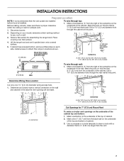
...exterior wall or roof opening . 3. Rectangular vent knockout NOTE: The 7" (17.8 cm) round vent mounting plate can be installed up under cabinet and determine final location by centering beneath cabinet. Use saber or keyhole saw to 1" (2.5 cm) on the range hood. Remove the 7" (17.8 cm) round vent mounting plate attached with the 3.5 x 9.5 mm screws provided. Install 7" (17.8 cm) round vent mounting plate. A B C D B A. 7" (17.8 cm) round vent mounting plate B. 3.5 x 9.5 mm screws 2. Round vent knockout E. Install Range Hood NOTE: Your model will have a 7" (17.8 cm) round vent...
...exterior wall or roof opening . 3. Rectangular vent knockout NOTE: The 7" (17.8 cm) round vent mounting plate can be installed up under cabinet and determine final location by centering beneath cabinet. Use saber or keyhole saw to 1" (2.5 cm) on the range hood. Remove the 7" (17.8 cm) round vent mounting plate attached with the 3.5 x 9.5 mm screws provided. Install 7" (17.8 cm) round vent mounting plate. A B C D B A. 7" (17.8 cm) round vent mounting plate B. 3.5 x 9.5 mm screws 2. Round vent knockout E. Install Range Hood NOTE: Your model will have a 7" (17.8 cm) round vent...

Installation Guide
Page 9
... direct wire installations, run the home power supply cable according to green ground screw in the terminal box. For optional power supply cord kit installations, follow the instructions in death, fire, or electrical shock. 4. Remove the screw from power supply to the National Electric Code or CSA standards and local codes and ordinances. Screw 3. Replace all parts and panels before servicing. Failure to make the connection in death or electrical shock. 1. Disconnect power. Using 2 or more people, lift the hood...
... direct wire installations, run the home power supply cable according to green ground screw in the terminal box. For optional power supply cord kit installations, follow the instructions in death, fire, or electrical shock. 4. Remove the screw from power supply to the National Electric Code or CSA standards and local codes and ordinances. Screw 3. Replace all parts and panels before servicing. Failure to make the connection in death or electrical shock. 1. Disconnect power. Using 2 or more people, lift the hood...
Installation Guide
Page 10
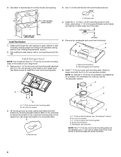
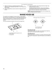
... the operation of the range hood. Disconnect power and check wiring connections. The hood controls are located on the top of the range hood fan and light. Filter retainer C. On/Off light switch B. Push the light switch to the left for Low speed. Install the 75W (max.) Incandescent light bulb. See the "Range Hood Care" section. 3. RANGE HOOD USE The range hood is complete to the left to turn the light On. Push the fan switch to remove smoke, cooking vapors and odors from the cooktop...
... the operation of the range hood. Disconnect power and check wiring connections. The hood controls are located on the top of the range hood fan and light. Filter retainer C. On/Off light switch B. Push the light switch to the left for Low speed. Install the 75W (max.) Incandescent light bulb. See the "Range Hood Care" section. 3. RANGE HOOD USE The range hood is complete to the left to turn the light On. Push the fan switch to remove smoke, cooking vapors and odors from the cooktop...

Installation Guide
Page 11
... rear of grain to avoid scratching or damaging the surface. RANGE HOOD CARE Cleaning IMPORTANT: Clean the hood and grease filters frequently according to range hood. 5. Metal Grease Filter 1. Remove screw from the hood. Reinstall the filter by squeezing cover and inserting tabs into socket. 4. A. Replace lens cover by placing the back edge in dishwasher or hot detergent solution. 4. Filter retainer 3. Disconnect power. 2. Light bulb socket B. If new light does not operate, make sure the lamp is inserted correctly before operating hood...
... rear of grain to avoid scratching or damaging the surface. RANGE HOOD CARE Cleaning IMPORTANT: Clean the hood and grease filters frequently according to range hood. 5. Metal Grease Filter 1. Remove screw from the hood. Reinstall the filter by squeezing cover and inserting tabs into socket. 4. A. Replace lens cover by placing the back edge in dishwasher or hot detergent solution. 4. Filter retainer 3. Disconnect power. 2. Light bulb socket B. If new light does not operate, make sure the lamp is inserted correctly before operating hood...

Installation Guide
Page 14
... 50 United States and Canada, this information on the model and serial number label located on how to use of purchase or installation date for other damage to the finish of the Use & Care Guide. Service calls to the appliance. 9. The cost of repair or replacement under this limited warranty. You must be borne by Whirlpool. 5. Costs associated with the removal from warranty coverage. 3. Dealer name Address Phone number Model number Serial number...
... 50 United States and Canada, this information on the model and serial number label located on how to use of purchase or installation date for other damage to the finish of the Use & Care Guide. Service calls to the appliance. 9. The cost of repair or replacement under this limited warranty. You must be borne by Whirlpool. 5. Costs associated with the removal from warranty coverage. 3. Dealer name Address Phone number Model number Serial number...

Use & Care Guide
Page 3
..., to the service panel. ■ Installation work and electrical wiring must always be burned. ■ DO NOT USE WATER, including wet dishcloths or towels a violent steam explosion will result. ■ Use an extinguisher ONLY if: - do not vent exhaust air into spaces within walls or ceilings, attics or into wall or ceiling; Heat oils slowly on accidentally. CAUTION: For general ventilating use to accumulate on "Kitchen Fire Safety...
..., to the service panel. ■ Installation work and electrical wiring must always be burned. ■ DO NOT USE WATER, including wet dishcloths or towels a violent steam explosion will result. ■ Use an extinguisher ONLY if: - do not vent exhaust air into spaces within walls or ceilings, attics or into wall or ceiling; Heat oils slowly on accidentally. CAUTION: For general ventilating use to accumulate on "Kitchen Fire Safety...

Use & Care Guide
Page 4
...; 7" (17.8 cm) round vent mounting plate ■ T-10 Torx®† adapter ■ 4 - 4.5 x 13 mm mounting screws Parts Needed ■ 7" (17.8 cm) round metal vent system ■ Wall or roof cap with washers and nuts (to match vent system ■ 1 - 75W max, 120V incandescent light bulb ■ 3 - Length and thickness determined by recess dimensions. ■ Four flat head wood screws or machine screws with damper to attach filler strips). The model/serial rating plate is a registered...
...; 7" (17.8 cm) round vent mounting plate ■ T-10 Torx®† adapter ■ 4 - 4.5 x 13 mm mounting screws Parts Needed ■ 7" (17.8 cm) round metal vent system ■ Wall or roof cap with washers and nuts (to match vent system ■ 1 - 75W max, 120V incandescent light bulb ■ 3 - Length and thickness determined by recess dimensions. ■ Four flat head wood screws or machine screws with damper to attach filler strips). The model/serial rating plate is a registered...
Use & Care Guide
Page 6
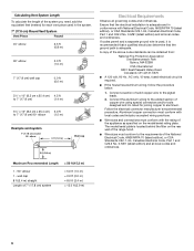
...., AC only, 15-amp, fused electrical circuit is adequate. Aluminum/copper connection must conform with local codes and industry accepted wiring practices. ■ Wire sizes and connections must conform to aluminum. wall cap 8 ft (2.4 m) straight Length of the appliance as specified on the rear wall of the range hood. ■ Wire sizes must conform with National Electrical Code, ANSI/NFPA 70 (latest edition), or CSA Standards C22.1-94, Canadian Electrical Code, Part 1 and C22...
...., AC only, 15-amp, fused electrical circuit is adequate. Aluminum/copper connection must conform with local codes and industry accepted wiring practices. ■ Wire sizes and connections must conform to aluminum. wall cap 8 ft (2.4 m) straight Length of the appliance as specified on the rear wall of the range hood. ■ Wire sizes must conform with National Electrical Code, ANSI/NFPA 70 (latest edition), or CSA Standards C22.1-94, Canadian Electrical Code, Part 1 and C22...

Use & Care Guide
Page 7
...;⁄₈" (28.9 cm) for 36" (91.4 cm) models Cut Openings for 7" (17.8 cm) Round Vent To make sure there is proper clearance within the ceiling or wall for exhaust vent. 1. Before making cutouts, make a circular vent openings on your model, determine which venting method to attach filler strips in the area the vent opening will be installed before hood is installed. Mark a line distance "A" from the right of the centerline...
...;⁄₈" (28.9 cm) for 36" (91.4 cm) models Cut Openings for 7" (17.8 cm) Round Vent To make sure there is proper clearance within the ceiling or wall for exhaust vent. 1. Before making cutouts, make a circular vent openings on your model, determine which venting method to attach filler strips in the area the vent opening will be installed before hood is installed. Mark a line distance "A" from the right of the centerline...
Use & Care Guide
Page 9
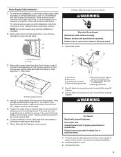
... terminal box. Remove terminal box cover and set aside. Using 2 or more people, lift the hood into final position. Tighten the mounting screws, making sure the screws are in the hood electrical terminal box. Connect ventwork to make connections in the terminal box. Black wires C. Green (or bare) ground wire E. UL listed or CSA approved ½" strain relief G. Failure to green ground screw in terminal box and securely tighten. 5. Terminal box cover B. Screw 3. Replace all parts and panels before servicing...
... terminal box. Remove terminal box cover and set aside. Using 2 or more people, lift the hood into final position. Tighten the mounting screws, making sure the screws are in the hood electrical terminal box. Connect ventwork to make connections in the terminal box. Black wires C. Green (or bare) ground wire E. UL listed or CSA approved ½" strain relief G. Failure to green ground screw in terminal box and securely tighten. 5. Terminal box cover B. Screw 3. Replace all parts and panels before servicing...

Use & Care Guide
Page 10
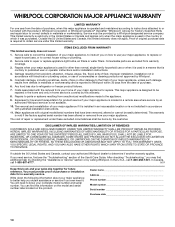
Complete Installation 1. Install the 75W (max.) Incandescent light bulb. Replace grease filter if removed. See "Range Hood Use" section. The hood controls are located on the top of the range hood fan and light. Push the fan switch to the left for Low speed. Fan speed switch Operating the light Push the light switch to the right to see whether a circuit breaker has tripped or a household fuse has blown. Disconnect power and check wiring connections. Filter retainer C. See the "Range Hood Care" section. 3. Push the light switch to the...
Complete Installation 1. Install the 75W (max.) Incandescent light bulb. Replace grease filter if removed. See "Range Hood Use" section. The hood controls are located on the top of the range hood fan and light. Push the fan switch to the left for Low speed. Fan speed switch Operating the light Push the light switch to the right to see whether a circuit breaker has tripped or a household fuse has blown. Disconnect power and check wiring connections. Filter retainer C. See the "Range Hood Care" section. 3. Push the light switch to the...

Use & Care Guide
Page 11
... with clean water and dry with soft, lint-free cloth. ■ Glass cleaner to range hood. 5. Metal Grease Filter 1. Reconnect power. A A. Filter retainer 3. Replace screw in direction of hood. Squeeze the plastic lens cover and remove it from the grease filter retainer. 2. A. Lens cover 3. Exterior Surfaces: IMPORTANT: Do not use cleaners that contain chlorine. If new light does not operate, make sure the lamp is inserted correctly before operating hood. Reinstall the filter by squeezing cover and inserting tabs...
... with clean water and dry with soft, lint-free cloth. ■ Glass cleaner to range hood. 5. Metal Grease Filter 1. Reconnect power. A A. Filter retainer 3. Replace screw in direction of hood. Squeeze the plastic lens cover and remove it from the grease filter retainer. 2. A. Lens cover 3. Exterior Surfaces: IMPORTANT: Do not use cleaners that contain chlorine. If new light does not operate, make sure the lamp is inserted correctly before operating hood. Reinstall the filter by squeezing cover and inserting tabs...

Use & Care Guide
Page 14
... "Troubleshooting" section of repair or replacement under this book and your sales slip together for other damage to the finish of your authorized Whirlpool dealer to correct house wiring or plumbing. 2. This limited warranty is valid only in the United States or Canada and applies only when the major appliance is covered by the customer. Service calls to or furnished with original model/serial numbers...
... "Troubleshooting" section of repair or replacement under this book and your sales slip together for other damage to the finish of your authorized Whirlpool dealer to correct house wiring or plumbing. 2. This limited warranty is valid only in the United States or Canada and applies only when the major appliance is covered by the customer. Service calls to or furnished with original model/serial numbers...
Warranty Information
Page 1
... replace or repair house fuses, or to determine if another warranty applies. This limited warranty is valid only in materials or workmanship and is used for future reference. Repairs to parts or systems resulting from your authorized Whirlpool dealer to correct house wiring or plumbing. 2. Major appliances with original model/serial numbers that is void if the factory applied serial number has been altered or removed from...
... replace or repair house fuses, or to determine if another warranty applies. This limited warranty is valid only in materials or workmanship and is used for future reference. Repairs to parts or systems resulting from your authorized Whirlpool dealer to correct house wiring or plumbing. 2. Major appliances with original model/serial numbers that is void if the factory applied serial number has been altered or removed from...


