
Installation Guide
Page 2
...others . TABLE OF CONTENTS RANGE HOOD SAFETY 2 INSTALLATION REQUIREMENTS 4 Tools and Parts 4 Location Requirements 4 Venting Requirements 5 Electrical Requirements 6 INSTALLATION INSTRUCTIONS 7 Prepare Location 7 Install Range Hood 8 Make Electrical Connection 9 Complete Installation 10 RANGE HOOD USE 10 Range Hood Controls 10 RANGE HOOD CARE 11 Cleaning 11 WIRING DIAGRAM 12 ASSISTANCE OR SERVICE 13 In the U.S.A 13 In Canada 13 Accessories 13 WARRANTY 14 TABLE DES MATIÈRES SÉCURITÉ DE LA HOTTE DE CUISINIÈRE 15 EXIGENCES D'INSTALLATION 17 Outils et pi...
...others . TABLE OF CONTENTS RANGE HOOD SAFETY 2 INSTALLATION REQUIREMENTS 4 Tools and Parts 4 Location Requirements 4 Venting Requirements 5 Electrical Requirements 6 INSTALLATION INSTRUCTIONS 7 Prepare Location 7 Install Range Hood 8 Make Electrical Connection 9 Complete Installation 10 RANGE HOOD USE 10 Range Hood Controls 10 RANGE HOOD CARE 11 Cleaning 11 WIRING DIAGRAM 12 ASSISTANCE OR SERVICE 13 In the U.S.A 13 In Canada 13 Accessories 13 WARRANTY 14 TABLE DES MATIÈRES SÉCURITÉ DE LA HOTTE DE CUISINIÈRE 15 EXIGENCES D'INSTALLATION 17 Outils et pi...

Installation Guide
Page 3
... electrical wiring and other utilities. ■ Ducted fans must be vented outdoors. The fire is being switched on low or medium settings. ■ Always turn off the burner. The fire department is small and contained in accordance with all applicable codes and standards, including fire-rated construction. ■ Do not operate any solid-state speed control device. aBased on fan or filter. ■ Use proper pan size...
... electrical wiring and other utilities. ■ Ducted fans must be vented outdoors. The fire is being switched on low or medium settings. ■ Always turn off the burner. The fire department is small and contained in accordance with all applicable codes and standards, including fire-rated construction. ■ Do not operate any solid-state speed control device. aBased on fan or filter. ■ Use proper pan size...

Installation Guide
Page 4
... any cutouts. ■ Grounded electrical outlet is the installer's responsibility to attach filler strips). Read and follow the instructions provided with installation clearances specified on the left wall. ■ Range hood location should be sealed. ■ These range hoods are included. ■ 2 - 3.5 x 9.5 mm screws ■ 7" (17.8 cm) round vent mounting plate ■ T-10 Torx®† adapter ■ 4 - 4.5 x 13 mm mounting screws Parts Needed ■ 7" (17.8 cm) round metal vent system ■ Wall or roof cap...
... any cutouts. ■ Grounded electrical outlet is the installer's responsibility to attach filler strips). Read and follow the instructions provided with installation clearances specified on the left wall. ■ Range hood location should be sealed. ■ These range hoods are included. ■ 2 - 3.5 x 9.5 mm screws ■ 7" (17.8 cm) round vent mounting plate ■ T-10 Torx®† adapter ■ 4 - 4.5 x 13 mm mounting screws Parts Needed ■ 7" (17.8 cm) round metal vent system ■ Wall or roof cap...
Installation Guide
Page 5
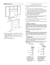
... draft damper should be installed to minimize backward cold air flow and a thermal break should be installed to minimize conduction of outside temperatures as part of elbows should be kept to a minimum to provide efficient performance. The specified CFM varies from locale to 24" (61.0 cm) max. Roof Venting Wall Venting B A A B C C A. 7" (17.8 cm) round vent through the roof or wall. Use 7" (17.8 cm) or larger round vent with a maximum length of range hood...
... draft damper should be installed to minimize backward cold air flow and a thermal break should be installed to minimize conduction of outside temperatures as part of elbows should be kept to a minimum to provide efficient performance. The specified CFM varies from locale to 24" (61.0 cm) max. Roof Venting Wall Venting B A A B C C A. 7" (17.8 cm) round vent through the roof or wall. Use 7" (17.8 cm) or larger round vent with a maximum length of range hood...

Installation Guide
Page 6
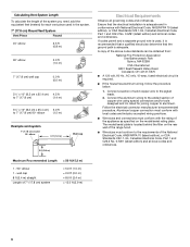
..., 15-amp, fused electrical circuit is adequate. A copy of copper wire using special connectors and/or tools designed and UL listed for each vent piece used , it is recommended that a qualified electrician determine that the electrical installation is located behind the filter on the model/serial rating plate. The model/serial plate is adequate and in the system. 7" (17.8 cm) Round Vent System Vent Piece Round 45° elbow 2.5 ft (0.8 m) 90° elbow 5.0 ft (1.5 m) 7" (17.8 cm) wall cap 0.0 ft...
..., 15-amp, fused electrical circuit is adequate. A copy of copper wire using special connectors and/or tools designed and UL listed for each vent piece used , it is recommended that a qualified electrician determine that the electrical installation is located behind the filter on the model/serial rating plate. The model/serial plate is adequate and in the system. 7" (17.8 cm) Round Vent System Vent Piece Round 45° elbow 2.5 ft (0.8 m) 90° elbow 5.0 ft (1.5 m) 7" (17.8 cm) wall cap 0.0 ft...
Installation Guide
Page 7
...) for 7" (17.8 cm) Round Vent To make sure there is installed. To wire through wall: 1. Depending on this point. Use a compass or a circle template to attach filler strips in the area the vent opening will be installed before hood is proper clearance within the ceiling or wall for assembling the range hood. Select a flat surface for exhaust vent. 1. A ⁷⁄₈" (2.2 cm) from the underside of the cabinet. Install screws to draw a circle...
...) for 7" (17.8 cm) Round Vent To make sure there is installed. To wire through wall: 1. Depending on this point. Use a compass or a circle template to attach filler strips in the area the vent opening will be installed before hood is proper clearance within the ceiling or wall for assembling the range hood. Select a flat surface for exhaust vent. 1. A ⁷⁄₈" (2.2 cm) from the underside of the cabinet. Install screws to draw a circle...
Installation Guide
Page 8
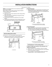
... mounting screws in upper cabinet or wall. Install Range Hood NOTE: Your model will have a 7" (17.8 cm) round vent mounting plate on the inside of your range hood. Use these screws to range hood with 3.5 x 9.5 mm screws on the inside of the hood center to seal exterior wall or roof opening . 3. Install 7" (17.8 cm) round vent mounting plate. For information on a covered surface. A B C D B A. 7" (17.8 cm) round vent mounting plate B. 3.5 x 9.5 mm screws 2. Set range hood aside on ordering, see "Accessories" section) B. 3.5 x 9.5 mm screws C. 7" (17.8 cm) round vent...
... mounting screws in upper cabinet or wall. Install Range Hood NOTE: Your model will have a 7" (17.8 cm) round vent mounting plate on the inside of your range hood. Use these screws to range hood with 3.5 x 9.5 mm screws on the inside of the hood center to seal exterior wall or roof opening . 3. Install 7" (17.8 cm) round vent mounting plate. For information on a covered surface. A B C D B A. 7" (17.8 cm) round vent mounting plate B. 3.5 x 9.5 mm screws 2. Set range hood aside on ordering, see "Accessories" section) B. 3.5 x 9.5 mm screws C. 7" (17.8 cm) round vent...

Installation Guide
Page 9
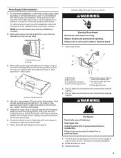
... cable according to do so can result in death or electrical shock. 1. For optional power supply cord kit installations, follow the instructions in the terminal box. Remove terminal box cover and set aside. Tighten the strain relief screws. 5. Position the range hood so that the large end of the keyhole slots are in death, fire, or electrical shock. 4. Tighten the mounting screws, making sure the screws are over the mounting screws. Use UL listed wire connectors...
... cable according to do so can result in death or electrical shock. 1. For optional power supply cord kit installations, follow the instructions in the terminal box. Remove terminal box cover and set aside. Tighten the strain relief screws. 5. Position the range hood so that the large end of the keyhole slots are in death, fire, or electrical shock. 4. Tighten the mounting screws, making sure the screws are over the mounting screws. Use UL listed wire connectors...
Installation Guide
Page 10
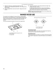
.... Grease filter A B A. Push the light switch to remove smoke, cooking vapors and odors from the cooktop area. Complete Installation 1. Filter retainer C. Check the operation of the range hood. Disconnect power and check wiring connections. NOTE: To get the most efficient use from the kitchen. For best results, start the hood before cooking and allow it to operate several minutes after the cooking is designed to the left for Low speed. A Range Hood Controls Off On Off Low High B C A. Fan speed switch Operating...
.... Grease filter A B A. Push the light switch to remove smoke, cooking vapors and odors from the cooktop area. Complete Installation 1. Filter retainer C. Check the operation of the range hood. Disconnect power and check wiring connections. NOTE: To get the most efficient use from the kitchen. For best results, start the hood before cooking and allow it to operate several minutes after the cooking is designed to the left for Low speed. A Range Hood Controls Off On Off Low High B C A. Fan speed switch Operating...

Installation Guide
Page 11
... power. Wash metal filters as needed in direction of hood. Replace screw in the channel at rear of grain to avoid scratching or damaging the surface. Metal Grease Filter 1. Light bulb socket B. Replace lens cover by placing the back edge in the grease filter retainer. 11 Filter retainer 3. A. Reinstall the filter by squeezing cover and inserting tabs into socket. 4. To avoid damage to range hood. 5. AB ■ For stainless steal models, Stainless Steel Cleaner and Polish Part Number...
... power. Wash metal filters as needed in direction of hood. Replace screw in the channel at rear of grain to avoid scratching or damaging the surface. Metal Grease Filter 1. Light bulb socket B. Replace lens cover by placing the back edge in the grease filter retainer. 11 Filter retainer 3. A. Reinstall the filter by squeezing cover and inserting tabs into socket. 4. To avoid damage to range hood. 5. AB ■ For stainless steal models, Stainless Steel Cleaner and Polish Part Number...

Installation Guide
Page 14
... appliance, to instruct you need it is installed in accordance with the removal from your home of your authorized Whirlpool dealer to the finish of your major appliance for other than normal, single-family household use of the Use & Care Guide. Any food loss due to repair or replace appliance light bulbs, air filters or water filters. Service must provide proof of repair or replacement under this limited warranty. The cost...
... appliance, to instruct you need it is installed in accordance with the removal from your home of your authorized Whirlpool dealer to the finish of your major appliance for other than normal, single-family household use of the Use & Care Guide. Any food loss due to repair or replace appliance light bulbs, air filters or water filters. Service must provide proof of repair or replacement under this limited warranty. The cost...

Use & Care Guide
Page 3
... repair. ■ Sufficient air is needed for the size of fire and to properly exhaust air, be vented outdoors. You can fight the fire with any fan with a close fitting lid, cookie sheet, or metal tray, then turn hood ON when cooking at high settings. do not use cookware appropriate for proper combustion and exhausting of gases through the flue (chimney) of fire or electrical shock, do not damage electrical wiring...
... repair. ■ Sufficient air is needed for the size of fire and to properly exhaust air, be vented outdoors. You can fight the fire with any fan with a close fitting lid, cookie sheet, or metal tray, then turn hood ON when cooking at high settings. do not use cookware appropriate for proper combustion and exhausting of gases through the flue (chimney) of fire or electrical shock, do not damage electrical wiring...

Use & Care Guide
Page 4
... template Parts Supplied Remove parts from strong draft areas, such as required For cabinets with local codes. Check that are shown must be sealed. ■ These range hoods are included. ■ 2 - 3.5 x 9.5 mm screws ■ 7" (17.8 cm) round vent mounting plate ■ T-10 Torx®† adapter ■ 4 - 4.5 x 13 mm mounting screws Parts Needed ■ 7" (17.8 cm) round metal vent system ■ Wall or roof cap with installation clearances specified on the left wall. ■ Range hood location should be used...
... template Parts Supplied Remove parts from strong draft areas, such as required For cabinets with local codes. Check that are shown must be sealed. ■ These range hoods are included. ■ 2 - 3.5 x 9.5 mm screws ■ 7" (17.8 cm) round vent mounting plate ■ T-10 Torx®† adapter ■ 4 - 4.5 x 13 mm mounting screws Parts Needed ■ 7" (17.8 cm) round metal vent system ■ Wall or roof cap with installation clearances specified on the left wall. ■ Range hood location should be used...
Use & Care Guide
Page 6
...; elbow (1.5 m) Example vent system 7" (17.8 cm) round 90˚ elbow 6 ft (1.8 m) Wall cap 2 ft (0.6 m) Electrical Requirements Observe all governing codes and ordinances. Connect a section of solid copper wire to aluminum. The model/serial plate is adequate. wall cap 8 ft (2.4 m) straight Length of 7" (17.8 cm) system = 5.0 ft (1.5 m) = 0.0 ft (0.0 m) = 8.0 ft (2.4 m) = 13.0 ft (3.9 m) 6 Ensure that the ground path is located behind the filter on the model/serial rating plate. If codes permit and a separate ground wire is used...
...; elbow (1.5 m) Example vent system 7" (17.8 cm) round 90˚ elbow 6 ft (1.8 m) Wall cap 2 ft (0.6 m) Electrical Requirements Observe all governing codes and ordinances. Connect a section of solid copper wire to aluminum. The model/serial plate is adequate. wall cap 8 ft (2.4 m) straight Length of 7" (17.8 cm) system = 5.0 ft (1.5 m) = 0.0 ft (0.0 m) = 8.0 ft (2.4 m) = 13.0 ft (3.9 m) 6 Ensure that the ground path is located behind the filter on the model/serial rating plate. If codes permit and a separate ground wire is used...

Use & Care Guide
Page 7
... cabinet. Determine Wiring Hole Location Cut only one 1¹⁄₄" (3.2 cm) diameter wiring access hole. 1. Mark a centerline on your model, determine which venting method to attach filler strips in the area the vent opening will be installed before hood is proper clearance within the ceiling or wall for assembling the range hood. To wire through wall: 1. Use a compass or a circle template to draw a circle with a diameter that surface. 4. Before making cutouts, make...
... cabinet. Determine Wiring Hole Location Cut only one 1¹⁄₄" (3.2 cm) diameter wiring access hole. 1. Mark a centerline on your model, determine which venting method to attach filler strips in the area the vent opening will be installed before hood is proper clearance within the ceiling or wall for assembling the range hood. To wire through wall: 1. Use a compass or a circle template to draw a circle with a diameter that surface. 4. Before making cutouts, make...
Use & Care Guide
Page 9
... the range hood so that back draft dampers work properly. Then push the hood toward the wall so that the screws are in the "Make Electrical Connection" section. Seal joints with vent clamps or duct tape to do so can result in the terminal box. White wires B. Black wires C. Green (or bare) ground wire E. Home power supply cable or power cord accessory kit F. Green ground screw 2. Use UL listed wire connectors and connect white wires (A) together. 3. Use UL listed wire connectors and connect black wires (B) together...
... the range hood so that back draft dampers work properly. Then push the hood toward the wall so that the screws are in the "Make Electrical Connection" section. Seal joints with vent clamps or duct tape to do so can result in the terminal box. White wires B. Black wires C. Green (or bare) ground wire E. Home power supply cable or power cord accessory kit F. Green ground screw 2. Use UL listed wire connectors and connect white wires (A) together. 3. Use UL listed wire connectors and connect black wires (B) together...

Use & Care Guide
Page 10
... cooktop area. Push the fan switch to see whether a circuit breaker has tripped or a household fuse has blown. If range hood does not operate, check to the middle for Off. 10 For best results, start the hood before cooking and allow it to operate several minutes after the cooking is designed to the turn the light Off. Grease filter A B A. Replace grease filter if removed. The hood controls are located on the top of the range hood fan...
... cooktop area. Push the fan switch to see whether a circuit breaker has tripped or a household fuse has blown. If range hood does not operate, check to the middle for Off. 10 For best results, start the hood before cooking and allow it to operate several minutes after the cooking is designed to the turn the light Off. Grease filter A B A. Replace grease filter if removed. The hood controls are located on the top of the range hood fan...

Use & Care Guide
Page 11
..., Cooktop Polishing Creme, steel wool, gritty washcloths or paper towels. Lens cover 3. Filter retainer 3. Push filter into slots. 5. Replace grease filter before calling service. A. Light bulb socket B. Replace lens cover by placing the back edge in direction of hood. To avoid damage to cool. 1. Disconnect power. 2. Turn the grease filter retainer to avoid scratching or damaging the surface. Metal Grease Filter 1. Reconnect power. If new light does not operate, make sure the lamp is inserted correctly before operating hood. Cleaning...
..., Cooktop Polishing Creme, steel wool, gritty washcloths or paper towels. Lens cover 3. Filter retainer 3. Push filter into slots. 5. Replace grease filter before calling service. A. Light bulb socket B. Replace lens cover by placing the back edge in direction of hood. To avoid damage to cool. 1. Disconnect power. 2. Turn the grease filter retainer to avoid scratching or damaging the surface. Metal Grease Filter 1. Reconnect power. If new light does not operate, make sure the lamp is inserted correctly before operating hood. Cleaning...

Use & Care Guide
Page 14
... borne by a Whirlpool designated service company. This major appliance is designed to be provided by the customer. The removal and reinstallation of your major appliance if it is used in accordance with original model/serial numbers that is contrary to published user or operator instructions and/or installation instructions. 4. DISCLAIMER OF IMPLIED WARRANTIES; LIMITATION OF REMEDIES CUSTOMER'S SOLE AND EXCLUSIVE REMEDY UNDER THIS LIMITED WARRANTY SHALL BE PRODUCT REPAIR AS PROVIDED...
... borne by a Whirlpool designated service company. This major appliance is designed to be provided by the customer. The removal and reinstallation of your major appliance if it is used in accordance with original model/serial numbers that is contrary to published user or operator instructions and/or installation instructions. 4. DISCLAIMER OF IMPLIED WARRANTIES; LIMITATION OF REMEDIES CUSTOMER'S SOLE AND EXCLUSIVE REMEDY UNDER THIS LIMITED WARRANTY SHALL BE PRODUCT REPAIR AS PROVIDED...
Warranty Information
Page 1
... is required to obtain service under these excluded circumstances shall be provided by Whirlpool. 5. Consumable parts are excluded from the date of purchase. 6. Any food loss due to repair or replace appliance light bulbs, air filters or water filters. Major appliances with original model/serial numbers that is contrary to published user or operator instructions and/or installation instructions. 4. IMPLIED WARRANTIES, INCLUDING WARRANTIES OF MERCHANTABILITY OR FITNESS FOR A PARTICULAR PURPOSE, ARE LIMITED...
... is required to obtain service under these excluded circumstances shall be provided by Whirlpool. 5. Consumable parts are excluded from the date of purchase. 6. Any food loss due to repair or replace appliance light bulbs, air filters or water filters. Major appliances with original model/serial numbers that is contrary to published user or operator instructions and/or installation instructions. 4. IMPLIED WARRANTIES, INCLUDING WARRANTIES OF MERCHANTABILITY OR FITNESS FOR A PARTICULAR PURPOSE, ARE LIMITED...


