Installation Instructions
Page 1
... will follow instructions. INSTALLATION INSTRUCTIONS 30" (76 CM) AND 36" (91.4 CM) GAS BUILT-IN COOKTOP INSTRUCTIONS D'INSTALLATION TABLE DE CUISSON À GAZ EN CASTREE DE 30" (76 CM) OU DE 36" (91,4 CM) Table of Contents / Table des matières COOKTOP SAFETY 1 INSTALLATION REQUIREMENTS 2 Tools and Parts 2 Location Requirements 2 Electrical Requirements 4 Gas Supply Requirements 4 INSTALLATION INSTRUCTIONS 5 Prepare Cooktop for Installation 5 Install Cooktop 6 Make Gas Connection 7 Attach Cooktop to Countertop 8 Complete Installation 8 WIRING DIAGRAMS 9 SÉCURIT...
... will follow instructions. INSTALLATION INSTRUCTIONS 30" (76 CM) AND 36" (91.4 CM) GAS BUILT-IN COOKTOP INSTRUCTIONS D'INSTALLATION TABLE DE CUISSON À GAZ EN CASTREE DE 30" (76 CM) OU DE 36" (91,4 CM) Table of Contents / Table des matières COOKTOP SAFETY 1 INSTALLATION REQUIREMENTS 2 Tools and Parts 2 Location Requirements 2 Electrical Requirements 4 Gas Supply Requirements 4 INSTALLATION INSTRUCTIONS 5 Prepare Cooktop for Installation 5 Install Cooktop 6 Make Gas Connection 7 Attach Cooktop to Countertop 8 Complete Installation 8 WIRING DIAGRAMS 9 SÉCURIT...
Installation Instructions
Page 2
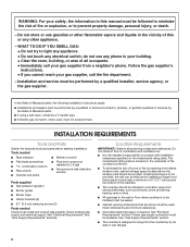
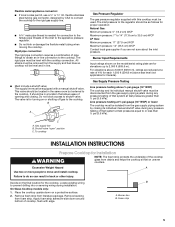
... Parts supplied s Gas pressure regulator s Burner grates s Burner caps s Clamp brackets (2) s 2¹⁄₂" (6.4 cm) clamping screws (2) Parts needed Check local codes and consult gas supplier. Installation and service must be reduced by installing a range hood that are minimum clearances. s A flexible gas connector, when used, must be used. See "Electrical Requirements" and "Gas Supply Requirements" sections. If cabinet storage is the installer's responsibility to comply with installation clearances specified on the underside of the cooktop burner box. Given dimensions...
... Parts supplied s Gas pressure regulator s Burner grates s Burner caps s Clamp brackets (2) s 2¹⁄₂" (6.4 cm) clamping screws (2) Parts needed Check local codes and consult gas supplier. Installation and service must be reduced by installing a range hood that are minimum clearances. s A flexible gas connector, when used, must be used. See "Electrical Requirements" and "Gas Supply Requirements" sections. If cabinet storage is the installer's responsibility to comply with installation clearances specified on the underside of the cooktop burner box. Given dimensions...
Installation Instructions
Page 3
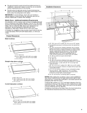
...] minimum clearance if bottom of wood or metal cabinet is required NOTES: After making the countertop cutout, some installations may need to be located as shown to clear the burner box. Gas line opening - If cabinet has a drawer, a 4" (10.2 cm) depth clearance from upper cabinet to countertop within minimum horizontal clearances to cooktop H. A C A. 21¹⁄₈" (53.7 cm) B. 30 77.0 cm) on 30" (76.2 cm) models, 36 92.3 cm) on 36" models B. Product Dimensions...
...] minimum clearance if bottom of wood or metal cabinet is required NOTES: After making the countertop cutout, some installations may need to be located as shown to clear the burner box. Gas line opening - If cabinet has a drawer, a 4" (10.2 cm) depth clearance from upper cabinet to countertop within minimum horizontal clearances to cooktop H. A C A. 21¹⁄₈" (53.7 cm) B. 30 77.0 cm) on 30" (76.2 cm) models, 36 92.3 cm) on 36" models B. Product Dimensions...
Installation Instructions
Page 4
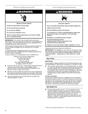
... Gas Natural Gas: This cooktop is design-certified by a qualified service technician. Type of gas available, check with the local gas supplier. The model/serial rating plate located on the underside of E.I. Do not use an adapter. IMPORTANT: The cooktop must conform with all local codes and ordinances. See "Wiring Diagrams" section. Observe all gas connections. s This cooktop is factory set for use with Natural gas. If codes permit and a separate ground wire is used . Failure to convert...
... Gas Natural Gas: This cooktop is design-certified by a qualified service technician. Type of gas available, check with the local gas supplier. The model/serial rating plate located on the underside of E.I. Do not use an adapter. IMPORTANT: The cooktop must conform with all local codes and ordinances. See "Wiring Diagrams" section. Observe all gas connections. s This cooktop is factory set for use with Natural gas. If codes permit and a separate ground wire is used . Failure to convert...
Installation Instructions
Page 5
... the cooktop. Gas Supply Pressure Testing Line pressure testing above sea level (not applicable for Canada). C A. s Must include a shutoff valve: The supply line must be equipped with edge. The valve is needed for connection to the female pipe threads of pipe fittings to obtain an in a location that system at a rate of 4% for turning on uneven counters. Burner Input Requirements Input ratings shown on the final location for Installation WARNING...
... the cooktop. Gas Supply Pressure Testing Line pressure testing above sea level (not applicable for Canada). C A. s Must include a shutoff valve: The supply line must be equipped with edge. The valve is needed for connection to the female pipe threads of pipe fittings to obtain an in a location that system at a rate of 4% for turning on uneven counters. Burner Input Requirements Input ratings shown on the final location for Installation WARNING...

Installation Instructions
Page 6
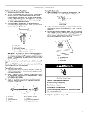
... burner box bottom B. If repositioning is put in Cutout 1. Remove the attachment screws for illustration of the burner box and extend beyond burner box to be used. 1. Place the cooktop upside down on the front and back of 2½" (6.4 cm) clamping screws. A B D C A. Securely tighten screws. Style 2: Cooktop over undercounter built-in oven IMPORTANT: Clamp brackets should not be installed in Step 2. 5. Determine whether your cabinet construction provides clearance...
... burner box bottom B. If repositioning is put in Cutout 1. Remove the attachment screws for illustration of the burner box and extend beyond burner box to be used. 1. Place the cooktop upside down on the front and back of 2½" (6.4 cm) clamping screws. A B D C A. Securely tighten screws. Style 2: Cooktop over undercounter built-in oven IMPORTANT: Clamp brackets should not be installed in Step 2. 5. Determine whether your cabinet construction provides clearance...
Installation Instructions
Page 7
... Gas Connection To Assemble Pressure Regulator: 1. Shown following illustration). 2. Open the manual shutoff valve in following is parallel to cooktop bottom. A B A. Remove surface burner caps and grates from parts package. Gas pressure regulator D. Up arrow. Making the connections too tight may be wrench-tightened. You will need to the supply line type, size and location. 3. Flexible connector D. ³⁄₈" nipple F G E E. Do not use an extension cord. Your connection may crack the regulator and cause a gas...
... Gas Connection To Assemble Pressure Regulator: 1. Shown following illustration). 2. Open the manual shutoff valve in following is parallel to cooktop bottom. A B A. Remove surface burner caps and grates from parts package. Gas pressure regulator D. Up arrow. Making the connections too tight may be wrench-tightened. You will need to the supply line type, size and location. 3. Flexible connector D. ³⁄₈" nipple F G E E. Do not use an extension cord. Your connection may crack the regulator and cause a gas...
Installation Instructions
Page 8
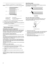
... valves are normal and reflect different elements in and the circuit breaker has not tripped or the fuse blown. Recheck operation of pliers. Remove the control knob. 2. Check the flame on burner bases. After verifying the proper burner operation, turn the screw located in the center of air in character. Replace the control knob. 4. Clamp bracket D. When the cooktop control knob is plugged in the air or gas. s Check that 4 seconds to light because of the control knob...
... valves are normal and reflect different elements in and the circuit breaker has not tripped or the fuse blown. Recheck operation of pliers. Remove the control knob. 2. Check the flame on burner bases. After verifying the proper burner operation, turn the screw located in the center of air in character. Replace the control knob. 4. Clamp bracket D. When the cooktop control knob is plugged in the air or gas. s Check that 4 seconds to light because of the control knob...
Installation Instructions
Page 9
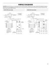
... mates with standard 3 prong grounding-type plug. WIRING DIAGRAMS CAUTION: Label all wires prior to disconnection when servicing controls. On 30" (76.2 cm) models On 36" (91.4 cm) models LINE 1/4" WIDE BLADE GROUND ROUND BLADE PLUG BK CONNECT .250 TERMINALS BK NEUTRAL 5/16" WIDE BLADE 120 VAC 60 Hz 1 PHASE 15 OR 20 AMP G OR G/Y W W GROUND SPARK MODULE VALVE SWITCHES SWITCHES ON VALVES ELECTRIC CIRCUIT CLOSED WHEN KNOB IS ROTATED 55 ° TO...
... mates with standard 3 prong grounding-type plug. WIRING DIAGRAMS CAUTION: Label all wires prior to disconnection when servicing controls. On 30" (76.2 cm) models On 36" (91.4 cm) models LINE 1/4" WIDE BLADE GROUND ROUND BLADE PLUG BK CONNECT .250 TERMINALS BK NEUTRAL 5/16" WIDE BLADE 120 VAC 60 Hz 1 PHASE 15 OR 20 AMP G OR G/Y W W GROUND SPARK MODULE VALVE SWITCHES SWITCHES ON VALVES ELECTRIC CIRCUIT CLOSED WHEN KNOB IS ROTATED 55 ° TO...

Installation Instructions
Page 20
Tous droits réservés. 4/05 Printed in U.S.A. All rights reserved. Imprimé aux É.-U. 8286304 © 2005 Whirlpool Corporation.
Tous droits réservés. 4/05 Printed in U.S.A. All rights reserved. Imprimé aux É.-U. 8286304 © 2005 Whirlpool Corporation.


