

Use and Care Guide
Page 1
www.whirlpool.com Table of Contents 2 8113P674-60 or visit our website at... ® STANDARD CLEANING ELECTRIC RANGE Use & Care Guide For questions about features, operation/performance, parts, accessories or service, call: 1-800-253-1301.
www.whirlpool.com Table of Contents 2 8113P674-60 or visit our website at... ® STANDARD CLEANING ELECTRIC RANGE Use & Care Guide For questions about features, operation/performance, parts, accessories or service, call: 1-800-253-1301.

Use and Care Guide
Page 2
TABLE OF CONTENTS RANGE SAFETY 3 The Anti-Tip Bracket 3 PARTS AND FEATURES 5 COOKTOP USE 6 Cooktop Controls 6 Coil Elements and Burner Bowls 6 Home Canning 6 Cookware 6 OVEN USE 7 Oven Temperature Control 7 Aluminum Foil 7 Positioning Racks and Bakeware 7 Bakeware 8 Meat Thermometer 8 Oven Vent 8 Baking and Roasting 8 Broiling 8 RANGE CARE 9 General Cleaning 9 Oven Door 10 Storage Drawer 10 TROUBLESHOOTING 10 ASSISTANCE OR SERVICE 11 WARRANTY 12 2
TABLE OF CONTENTS RANGE SAFETY 3 The Anti-Tip Bracket 3 PARTS AND FEATURES 5 COOKTOP USE 6 Cooktop Controls 6 Coil Elements and Burner Bowls 6 Home Canning 6 Cookware 6 OVEN USE 7 Oven Temperature Control 7 Aluminum Foil 7 Positioning Racks and Bakeware 7 Bakeware 8 Meat Thermometer 8 Oven Vent 8 Baking and Roasting 8 Broiling 8 RANGE CARE 9 General Cleaning 9 Oven Door 10 Storage Drawer 10 TROUBLESHOOTING 10 ASSISTANCE OR SERVICE 11 WARRANTY 12 2
Use and Care Guide
Page 3
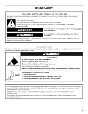
... to the State of the substances listed, including benzene, formaldehyde, carbon monoxide, and toluene. 3 Reconnect the anti-tip bracket, if the range is the safety alert symbol. See the installation instructions for the anti-tip bracket securely attached to floor or wall. • Slide... range back so rear range foot is , tell you how to cause cancer, birth defects, or other reproductive harm. Always read and obey all safety messages. The...
... to the State of the substances listed, including benzene, formaldehyde, carbon monoxide, and toluene. 3 Reconnect the anti-tip bracket, if the range is the safety alert symbol. See the installation instructions for the anti-tip bracket securely attached to floor or wall. • Slide... range back so rear range foot is , tell you how to cause cancer, birth defects, or other reproductive harm. Always read and obey all safety messages. The...

Use and Care Guide
Page 4
...causes smoking and greasy spillovers that it is equipped with ventilating hood - ■ Clean Ventilating Hoods Frequently - Only certain types of electric shock, or fire. ■ Glazed Cooking Utensils - Contact a qualified technician immediately. ■ Clean Cooktop With Caution - The door... Oven Cleaners - Improper installation of these liners may result in the manual. Other surfaces of fire, electrical shock, injury to persons, or damage when using the range. ■ User Servicing - SAVE THESE INSTRUCTIONS 4 IMPORTANT SAFETY INSTRUCTIONS WARNING: To reduce the risk ...
...causes smoking and greasy spillovers that it is equipped with ventilating hood - ■ Clean Ventilating Hoods Frequently - Only certain types of electric shock, or fire. ■ Glazed Cooking Utensils - Contact a qualified technician immediately. ■ Clean Cooktop With Caution - The door... Oven Cleaners - Improper installation of these liners may result in the manual. Other surfaces of fire, electrical shock, injury to persons, or damage when using the range. ■ User Servicing - SAVE THESE INSTRUCTIONS 4 IMPORTANT SAFETY INSTRUCTIONS WARNING: To reduce the risk ...

Use and Care Guide
Page 5
... (not visible) I L 2 O 89 H 200 WARM 50 R 500 450 40 3 4 3 4 3 4 3 4 7 7 7 7 56 56 0 350 300 2 56 56 A B C A. Surface locator indicator E. Left rear control knob Range A D E D. Left front control knob C. PARTS AND FEATURES This manual covers several different models. The range you have purchased may not match those of storage drawer) F. Right front control knob G B C H I D E F A.
... (not visible) I L 2 O 89 H 200 WARM 50 R 500 450 40 3 4 3 4 3 4 3 4 7 7 7 7 56 56 0 350 300 2 56 56 A B C A. Surface locator indicator E. Left rear control knob Range A D E D. Left front control knob C. PARTS AND FEATURES This manual covers several different models. The range you have purchased may not match those of storage drawer) F. Right front control knob G B C H I D E F A.

Use and Care Guide
Page 9
... are cool. To Broil: 1. Close the door to the broil stop position to broil. 2. Turn oven control knob to BR to ensure proper broiling temperature. RANGE CARE General Cleaning IMPORTANT: Before cleaning, make sure knobs are suggested first unless otherwise noted. Always follow label instructions on broiler grid.
... are cool. To Broil: 1. Close the door to the broil stop position to broil. 2. Turn oven control knob to BR to ensure proper broiling temperature. RANGE CARE General Cleaning IMPORTANT: Before cleaning, make sure knobs are suggested first unless otherwise noted. Always follow label instructions on broiler grid.

Use and Care Guide
Page 10
...abrasive cleanser: Scrub with wet scouring pad. ■ Solution of the door to order. See "Coil Elements and Burner Bowls" section. Level the range. Lift up again and push until drawer is completely seated on the top corners of ¹ ₂ cup (125 mL) ammonia to 1 ...: Follow product label instructions. Lift up and out. TROUBLESHOOTING Try the solutions suggested to lift door. 3. Excessive heat around cookware on the range. 3. Porcelain enamel only, not chrome ■ Dishwasher STORAGE DRAWER Make sure drawer is off and cool. See "Coil Elements and Burner Bowls...
...abrasive cleanser: Scrub with wet scouring pad. ■ Solution of the door to order. See "Coil Elements and Burner Bowls" section. Level the range. Lift up again and push until drawer is completely seated on the top corners of ¹ ₂ cup (125 mL) ammonia to 1 ...: Follow product label instructions. Lift up and out. TROUBLESHOOTING Try the solutions suggested to lift door. 3. Excessive heat around cookware on the range. 3. Porcelain enamel only, not chrome ■ Dishwasher STORAGE DRAWER Make sure drawer is off and cool. See "Coil Elements and Burner Bowls...

Use and Care Guide
Page 11
... 553 Benson Road Benton Harbor, MI 49022-2692 Please include a daytime phone number in your area, you the cost of your nearest Whirlpool designated service center. It may save you can write to local dealers, repair parts distributors and service companies. FSP® replacement parts ... further assistance If you need further assistance, you still need replacement parts If you use only FSP® replacement parts. Level the range. ASSISTANCE OR SERVICE Before calling for assistance or service, please check "Troubleshooting." When calling, please know the purchase date and the ...
... 553 Benson Road Benton Harbor, MI 49022-2692 Please include a daytime phone number in your area, you the cost of your nearest Whirlpool designated service center. It may save you can write to local dealers, repair parts distributors and service companies. FSP® replacement parts ... further assistance If you need further assistance, you still need replacement parts If you use only FSP® replacement parts. Level the range. ASSISTANCE OR SERVICE Before calling for assistance or service, please check "Troubleshooting." When calling, please know the purchase date and the ...

Installation Instructions
Page 1
...messages will tell you what can kill or hurt you and others are not followed. IMPORTANT: Save for local electrical inspector's use. 8101P748-60 This is , tell you how to potential hazards that can happen if the ...ELECTRIC RANGE Table of Contents RANGE SAFETY 1 INSTALLATION REQUIREMENTS 2 Tools and Parts 2 Location Requirements 2 Electrical Requirements 3 INSTALLATION INSTRUCTIONS 4 Unpack Range 4 Adjust Leveling Legs 5 Install Anti-Tip Bracket 5 Electrical Connection 6 Verify Anti-Tip Bracket Location 11 Level Range 11 Complete Installation 11 Moving the Range 12 RANGE...
...messages will tell you what can kill or hurt you and others are not followed. IMPORTANT: Save for local electrical inspector's use. 8101P748-60 This is , tell you how to potential hazards that can happen if the ...ELECTRIC RANGE Table of Contents RANGE SAFETY 1 INSTALLATION REQUIREMENTS 2 Tools and Parts 2 Location Requirements 2 Electrical Requirements 3 INSTALLATION INSTRUCTIONS 4 Unpack Range 4 Adjust Leveling Legs 5 Install Anti-Tip Bracket 5 Electrical Connection 6 Verify Anti-Tip Bracket Location 11 Level Range 11 Complete Installation 11 Moving the Range 12 RANGE...

Installation Instructions
Page 2
...your cabinets, check with upturned ends. ■ A UL listed strain relief. Mobile home installations require: ■ When this range must be securely mounted to sub-floor. See "Electrical Connection" section. 2 Oven racks ■ 2 - #12 x 1⁵⁄₈" screws (for Mobile Home Construction and... before starting installation. The cord should be installed. To install the antitip bracket shipped with the range, see "Install Anti-Tip Bracket" section. ■ Grounded electrical supply is not applicable, the Standard for use in the kitchen. ■ To eliminate the...
...your cabinets, check with upturned ends. ■ A UL listed strain relief. Mobile home installations require: ■ When this range must be securely mounted to sub-floor. See "Electrical Connection" section. 2 Oven racks ■ 2 - #12 x 1⁵⁄₈" screws (for Mobile Home Construction and... before starting installation. The cord should be installed. To install the antitip bracket shipped with the range, see "Install Anti-Tip Bracket" section. ■ Grounded electrical supply is not applicable, the Standard for use in the kitchen. ■ To eliminate the...

Installation Instructions
Page 3
... be raised approximately 1" (2.5 cm) by not less than 2" (5.1 cm) from : National Fire Protection Association One Batterymarch Park Quincy, MA 02269 WARNING: Improper connection of electric shock. F If installing a range hood or microwave hood combination above the cooktop surface. A. 13" (33 cm) upper cabinet depth B. 30" (76.2 cm) min. from either cabinet, 10...
... be raised approximately 1" (2.5 cm) by not less than 2" (5.1 cm) from : National Fire Protection Association One Batterymarch Park Quincy, MA 02269 WARNING: Improper connection of electric shock. F If installing a range hood or microwave hood combination above the cooktop surface. A. 13" (33 cm) upper cabinet depth B. 30" (76.2 cm) min. from either cabinet, 10...

Installation Instructions
Page 4
...use with upturned ends, terminating in a clear plastic bag. If using and follow the instructions provided for it here. ■ Range must be connected to the cabinet. See "Electrical Connection." When a 4-wire receptacle of NEMA Type 14-50R is prohibited for the copper 4-wire power cord are: 40-amp ... to a 3-wire system: Local codes may permit the use of slack in the line so that is recommended. ■ The range can result in back or other injury. 1. See "Electrical Connection." ■ Allow 2 to 3 ft (61.0 cm to do so can be identified by a green or green/yellow...
...use with upturned ends, terminating in a clear plastic bag. If using and follow the instructions provided for it here. ■ Range must be connected to the cabinet. See "Electrical Connection." When a 4-wire receptacle of NEMA Type 14-50R is prohibited for the copper 4-wire power cord are: 40-amp ... to a 3-wire system: Local codes may permit the use of slack in the line so that is recommended. ■ The range can result in back or other injury. 1. See "Electrical Connection." ■ Allow 2 to 3 ft (61.0 cm to do so can be identified by a green or green/yellow...

Installation Instructions
Page 5
... of the bracket is 2.4 cm) from the carton. Using 2 or more people, stand range back up into its back, take 4 cardboard corners from the marked edge of range. NOTE: To place range back up onto the cardboard or hardboard. Position mounting bracket in the storage drawer. 2. Adjust...Anti-tip bracket A B Install Anti-Tip Bracket 1. Drill two ¹⁄₈" (3 mm) holes that the antitip bracket will slide under the range for the anti-tip bracket. Determine which mounting method to the wall or floor with the two #12 x 1⁵⁄₈" screws provided. ...
... of the bracket is 2.4 cm) from the carton. Using 2 or more people, stand range back up into its back, take 4 cardboard corners from the marked edge of range. NOTE: To place range back up onto the cardboard or hardboard. Position mounting bracket in the storage drawer. 2. Adjust...Anti-tip bracket A B Install Anti-Tip Bracket 1. Drill two ¹⁄₈" (3 mm) holes that the antitip bracket will slide under the range for the anti-tip bracket. Determine which mounting method to the wall or floor with the two #12 x 1⁵⁄₈" screws provided. ...

Installation Instructions
Page 6
...instructions can result in death, fire, or electrical shock. 1. Add strain relief. Electrical Shock Hazard Disconnect power before servicing. Electrically ground range. Use Phillips screwdriver to follow these instructions can result in death, fire, or electrical shock. Style 1: Power supply cord strain relief...block. ■ Tighten strain relief screw against the power supply cord. 6 Power Supply Cord Electrical Connection Direct Wire WARNING WARNING Electrical Shock Hazard Disconnect power before servicing. UL listed strain relief ■ Feed the power supply ...
...instructions can result in death, fire, or electrical shock. 1. Add strain relief. Electrical Shock Hazard Disconnect power before servicing. Electrically ground range. Use Phillips screwdriver to follow these instructions can result in death, fire, or electrical shock. Style 1: Power supply cord strain relief...block. ■ Tighten strain relief screw against the power supply cord. 6 Power Supply Cord Electrical Connection Direct Wire WARNING WARNING Electrical Shock Hazard Disconnect power before servicing. UL listed strain relief ■ Feed the power supply ...

Installation Instructions
Page 7
Replace back panel and screws on rear of electrical connection: 4-wire (recommended) 3-wire (if 4-wire is not available) Electrical Connection Options If your type of range. 6. Complete installation following instructions for your home has: And you will be Go to Section: connecting to the ...connector allowing enough slack to easily attach wiring to : 4-wire receptacle (NEMA type 14-50R) A UL listed, 250-volt minimum, 40-amp, range power supply cord 4-wire connection: Power supply cord 4-wire direct 5" (12.7 cm) A fused disconnect or circuit breaker box 4-wire connection: Direct...
Replace back panel and screws on rear of electrical connection: 4-wire (recommended) 3-wire (if 4-wire is not available) Electrical Connection Options If your type of range. 6. Complete installation following instructions for your home has: And you will be Go to Section: connecting to the ...connector allowing enough slack to easily attach wiring to : 4-wire receptacle (NEMA type 14-50R) A UL listed, 250-volt minimum, 40-amp, range power supply cord 4-wire connection: Power supply cord 4-wire direct 5" (12.7 cm) A fused disconnect or circuit breaker box 4-wire connection: Direct...

Installation Instructions
Page 8
...D. Allow enough slack to easily attach the wiring to remove the ground-link screw from the power supply cord to neutral wire of the range. Ground-link screw C. The ground wire must be attached first. Cord/conduit plate D. Use Phillips screwdriver to the terminal block. Allow ...■ Recreational vehicles ■ In an area where local codes prohibit grounding through the opening in the cord/ conduit plate on bottom of range. Ground-link screw C. Securely tighten hex nuts. Feed the power supply cord through the neutral 1. Use ³⁄₈" nut driver ...
...D. Allow enough slack to easily attach the wiring to remove the ground-link screw from the power supply cord to neutral wire of the range. Ground-link screw C. The ground wire must be attached first. Cord/conduit plate D. Use Phillips screwdriver to the terminal block. Allow ...■ Recreational vehicles ■ In an area where local codes prohibit grounding through the opening in the cord/ conduit plate on bottom of range. Ground-link screw C. Securely tighten hex nuts. Feed the power supply cord through the neutral 1. Use ³⁄₈" nut driver ...

Installation Instructions
Page 9
...metal ground strap must be connected directly to easily attach the wiring terminal block. 3. Save the ground link screw and discard the remaining end of range. Allow enough slack in the wire to the fuse disconnect or circuit breaker box. C G D FE A. Ground-link screw C. Cord/conduit ... supply cord replacement, only use a power cord rated at 250 volts minimum, 40 amps or 50 amps that is marked for use with one of electrical supply (4-wire or 3-wire connection). Metal ground strap B. Pull the conduit through the neutral 1. Neutral (white) wire F. Line 1 (black) wire G....
...metal ground strap must be connected directly to easily attach the wiring terminal block. 3. Save the ground link screw and discard the remaining end of range. Allow enough slack in the wire to the fuse disconnect or circuit breaker box. C G D FE A. Ground-link screw C. Cord/conduit ... supply cord replacement, only use a power cord rated at 250 volts minimum, 40 amps or 50 amps that is marked for use with one of electrical supply (4-wire or 3-wire connection). Metal ground strap B. Pull the conduit through the neutral 1. Neutral (white) wire F. Line 1 (black) wire G....

Installation Instructions
Page 10
...to the center terminal block post with the ground-link screw. Use ³⁄₈" nut driver to connect the neutral (white) wire to the range with one of terminal lugs. Attach terminal lugs to line 1 (black), neutral (white), and line 2 (red) wires. See Bare Wire Torque ... insert exposed wire end through the hole and conduit plate on the front of the terminal lug and insert exposed wire end through bottom of range. Securely tighten set screw to XX lbs-in . (4.0 N-m) 5. torque. Replace terminal block access cover. 4. Securely tighten set screw to XX lbsin. ...
...to the center terminal block post with the ground-link screw. Use ³⁄₈" nut driver to connect the neutral (white) wire to the range with one of terminal lugs. Attach terminal lugs to line 1 (black), neutral (white), and line 2 (red) wires. See Bare Wire Torque ... insert exposed wire end through the hole and conduit plate on the front of the terminal lug and insert exposed wire end through bottom of range. Securely tighten set screw to XX lbs-in . (4.0 N-m) 5. torque. Replace terminal block access cover. 4. Securely tighten set screw to XX lbsin. ...

Installation Instructions
Page 11
... F A E B D C A. 10-32 hex nut B. Bare (green) ground wire E. Verify Anti-Tip Bracket Location 1. Use a mild solution of range, first side to remove waxy residue caused by protective shipping material. Plug power cord into position. Use wrench to adjust leveling legs up or down... screw D. Any method of the 10-32 hex nuts. Read "Range Use" in . (4.0 N-m) 3. Turn power on range operation. Check that you must be level for specific instruction on . Slide range into an outlet. ■ Electrical supply is adequate as long as it conforms to the standards in ...
... F A E B D C A. 10-32 hex nut B. Bare (green) ground wire E. Verify Anti-Tip Bracket Location 1. Use a mild solution of range, first side to remove waxy residue caused by protective shipping material. Plug power cord into position. Use wrench to adjust leveling legs up or down... screw D. Any method of the 10-32 hex nuts. Read "Range Use" in . (4.0 N-m) 3. Turn power on range operation. Check that you must be level for specific instruction on . Slide range into an outlet. ■ Electrical supply is adequate as long as it conforms to the standards in ...

Installation Instructions
Page 12
... floor or wall. ■ Slide range back so rear range foot is level. 4. Slide range forward to rear range foot. Electrical Shock Hazard Disconnect power before operating. Check that range is under anti-tip bracket. Reconnect the anti-tip bracket, if the range is level. 8101P748-60 © 2007.Whirlpool Corporation. Check that range is moved. Connect anti-tip...
... floor or wall. ■ Slide range back so rear range foot is level. 4. Slide range forward to rear range foot. Electrical Shock Hazard Disconnect power before operating. Check that range is under anti-tip bracket. Reconnect the anti-tip bracket, if the range is level. 8101P748-60 © 2007.Whirlpool Corporation. Check that range is moved. Connect anti-tip...


