
Dimension Guide
Page 1
... NOTE*. from either cabinet, 5¹⁄₂" (14.0 cm) max. Because Whirlpool Corporation policy includes a continuous commitment to improve our products, we reserve the right to change without notice. The range can be raised approximately 1" (2.5 cm) by not less than 1/4" (6.4 mm) ..." (61 cm) min. W10252706A 1/04/10 Model/serial rating plate (located on the oven frame behind storage drawer panel) *Range can be connected to the cabinet. The model/serial number rating plate is recommended. CABINET OPENING DIMENSIONS Cabinet opening width E. opening ...
... NOTE*. from either cabinet, 5¹⁄₂" (14.0 cm) max. Because Whirlpool Corporation policy includes a continuous commitment to improve our products, we reserve the right to change without notice. The range can be raised approximately 1" (2.5 cm) by not less than 1/4" (6.4 mm) ..." (61 cm) min. W10252706A 1/04/10 Model/serial rating plate (located on the oven frame behind storage drawer panel) *Range can be connected to the cabinet. The model/serial number rating plate is recommended. CABINET OPENING DIMENSIONS Cabinet opening width E. opening ...

Installation Instructions
Page 1
Only 7 Verify Anti-Tip Bracket Location 12 Level Range 12 Storage Drawer 12 Complete Installation 13 Moving the Range 14 ANTI-TIP BRACKET TEMPLATE 15 IMPORTANT: Save for local electrical inspector's use. U.S.A. U.S.A. Only 4 INSTALLATION INSTRUCTIONS 6 Unpack Range 6 Install Anti-Tip Bracket 6 Electrical Connection - W10252706B INSTALLATION INSTRUCTIONS 30" (76 CM) FREESTANDING ELECTRIC RANGES Table of Contents RANGE SAFETY 2 INSTALLATION REQUIREMENTS 3 Tools and Parts 3 Location Requirements 3 Electrical Requirements -
Only 7 Verify Anti-Tip Bracket Location 12 Level Range 12 Storage Drawer 12 Complete Installation 13 Moving the Range 14 ANTI-TIP BRACKET TEMPLATE 15 IMPORTANT: Save for local electrical inspector's use. U.S.A. U.S.A. Only 4 INSTALLATION INSTRUCTIONS 6 Unpack Range 6 Install Anti-Tip Bracket 6 Electrical Connection - W10252706B INSTALLATION INSTRUCTIONS 30" (76 CM) FREESTANDING ELECTRIC RANGES Table of Contents RANGE SAFETY 2 INSTALLATION REQUIREMENTS 3 Tools and Parts 3 Location Requirements 3 Electrical Requirements -

Installation Instructions
Page 2
... or seriously injured if you what the potential hazard is, tell you how to follow instructions. Reconnect the anti-tip bracket, if the range is the safety alert symbol. Failure to reduce the chance of others . All safety messages will tell you what can happen if the ... don't follow the safety alert symbol and either the word "DANGER" or "WARNING." This is moved. All safety messages will follow instructions. RANGE SAFETY Your safety and the safety of injury, and tell you don't immediately follow these instructions can result in this manual and on your appliance...
... or seriously injured if you what the potential hazard is, tell you how to follow instructions. Reconnect the anti-tip bracket, if the range is the safety alert symbol. Failure to reduce the chance of others . All safety messages will tell you what can happen if the ... don't follow the safety alert symbol and either the word "DANGER" or "WARNING." This is moved. All safety messages will follow instructions. RANGE SAFETY Your safety and the safety of injury, and tell you don't immediately follow these instructions can result in this manual and on your appliance...

Installation Instructions
Page 3
... or cable must be used will need to comply with installation clearances specified on the left side frame behind the storage drawer panel. ■ The range should be avoided. Terminal lugs A B C A. Plastic anchors (2) C. #10 x 1¹⁄₂" screws (2) ■ Anti-tip bracket ... standard is installed in accordance with the requirements of 194° (90°C). Mobile home installations require: ■ When this range must be made by a licensed, qualified electrical installer. Any method of flooring may require longer screws to anchor bracket to the ...
... or cable must be used will need to comply with installation clearances specified on the left side frame behind the storage drawer panel. ■ The range should be avoided. Terminal lugs A B C A. Plastic anchors (2) C. #10 x 1¹⁄₂" screws (2) ■ Anti-tip bracket ... standard is installed in accordance with the requirements of 194° (90°C). Mobile home installations require: ■ When this range must be made by a licensed, qualified electrical installer. Any method of flooring may require longer screws to anchor bracket to the ...

Installation Instructions
Page 4
...and the bottom of electric shock. Cabinet Dimensions Cabinet opening dimensions shown are in a risk of an uncovered wood or metal cabinet. A freestanding range may be raised approximately 1" (2.5 cm) by not less than ¹⁄₄" (0.64 cm) flame retardant millboard covered with leveling legs... (33.0 cm) max. Do not use an extension cord. Model/serial rating plate (located on the left side frame behind storage drawer panel) *Range can be installed next to whether the appliance is used, it will not fit the outlet, have a proper outlet installed by a qualified electrician. 4...
...and the bottom of electric shock. Cabinet Dimensions Cabinet opening dimensions shown are in a risk of an uncovered wood or metal cabinet. A freestanding range may be raised approximately 1" (2.5 cm) by not less than ¹⁄₄" (0.64 cm) flame retardant millboard covered with leveling legs... (33.0 cm) max. Do not use an extension cord. Model/serial rating plate (located on the left side frame behind storage drawer panel) *Range can be installed next to whether the appliance is used, it will not fit the outlet, have a proper outlet installed by a qualified electrician. 4...

Installation Instructions
Page 5
...sizes and connections must conform with the neutral terminal connected to the neutral by a white cover. If connecting to a 4-wire system: This range is ever necessary. ■ A UL listed conduit connector must be connected directly to the circuit breaker box (or fused disconnect) through the ... with a nominal 1³⁄₈" (34.9 mm) diameter connection opening. ■ A circuit breaker is recommended. ■ The range can be moved if servicing is manufactured with a UL listed strain relief and be connected to the proper electrical voltage and frequency as specified...
...sizes and connections must conform with the neutral terminal connected to the neutral by a white cover. If connecting to a 4-wire system: This range is ever necessary. ■ A UL listed conduit connector must be connected directly to the circuit breaker box (or fused disconnect) through the ... with a nominal 1³⁄₈" (34.9 mm) diameter connection opening. ■ A circuit breaker is recommended. ■ The range can be moved if servicing is manufactured with a UL listed strain relief and be connected to the proper electrical voltage and frequency as specified...

Installation Instructions
Page 6
...injury. 1. Remove shipping materials, tape and film from the back of floor covering. Remove oven racks and parts package from outside the range. Shipping base 4. AB C If cabinet opening so that specified in cabinet opening is wider than that the left edge is against rear... wall, molding or cabinet. 3. Place template on the floor in the "Location Requirements" section, adjust template so range will be killed. On Ranges Equipped with Storage Drawers: Remove the storage drawer. Failure to lower front leveling legs one-half turn . Contact a qualified floor...
...injury. 1. Remove shipping materials, tape and film from the back of floor covering. Remove oven racks and parts package from outside the range. Shipping base 4. AB C If cabinet opening so that specified in cabinet opening is wider than that the left edge is against rear... wall, molding or cabinet. 3. Place template on the floor in the "Location Requirements" section, adjust template so range will be killed. On Ranges Equipped with Storage Drawers: Remove the storage drawer. Failure to lower front leveling legs one-half turn . Contact a qualified floor...

Installation Instructions
Page 7
...Hazard Disconnect power before servicing. Use 8 gauge copper or 6 gauge aluminum wire. Electrically ground range. Disconnect power. 2. Remove the terminal block cover screws located on the thickness of the range. Pull cover down and toward you to the subfloor. Remove plastic tag holding three 10-32... hex nuts from your flooring, longer screws may be necessary to anchor the bracket to remove cover from range. 3. A B C A. Hex-head screws ...
...Hazard Disconnect power before servicing. Use 8 gauge copper or 6 gauge aluminum wire. Electrically ground range. Disconnect power. 2. Remove the terminal block cover screws located on the thickness of the range. Pull cover down and toward you to the subfloor. Remove plastic tag holding three 10-32... hex nuts from your flooring, longer screws may be necessary to anchor the bracket to remove cover from range. 3. A B C A. Hex-head screws ...

Installation Instructions
Page 8
...Ground-link screw 2. Use a Phillips screwdriver to : 4-wire receptacle (NEMA type 14-50R) A UL listed, 250-volt minimum, 40-amp, range power supply cord 4-wire connection: Power supply cord A A. Removable retaining nut B. Part of the ground-link under the screw. 8 Electrical Connection Options... If your type of the range. Discard C. Add strain relief. Save the ground-link screw and the end of metal ground strap must be Go to Section: connecting...
...Ground-link screw 2. Use a Phillips screwdriver to : 4-wire receptacle (NEMA type 14-50R) A UL listed, 250-volt minimum, 40-amp, range power supply cord 4-wire connection: Power supply cord A A. Removable retaining nut B. Part of the ground-link under the screw. 8 Electrical Connection Options... If your type of the range. Discard C. Add strain relief. Save the ground-link screw and the end of metal ground strap must be Go to Section: connecting...

Installation Instructions
Page 9
...amps that is marked for use with nominal 1³⁄₈" (3.5 cm) diameter connection opening, with ring terminals and marked for use with ranges. 5. A B C D A. Ground-link screw C. C D A. Use ³⁄₈" nut driver to connect the neutral (white)... supply cord. 1. UL listed strain relief D. Line 2 (red) D D. Connect line 2 (red) and line 1 (black) wires to the range with nominal 1³⁄₈" (3.5 cm) diameter connection opening 2. Replace terminal block access cover. 9 UL listed strain relief D. Replace terminal block access...
...amps that is marked for use with nominal 1³⁄₈" (3.5 cm) diameter connection opening, with ring terminals and marked for use with ranges. 5. A B C D A. Ground-link screw C. C D A. Use ³⁄₈" nut driver to connect the neutral (white)... supply cord. 1. UL listed strain relief D. Line 2 (red) D D. Connect line 2 (red) and line 1 (black) wires to the range with nominal 1³⁄₈" (3.5 cm) diameter connection opening 2. Replace terminal block access cover. 9 UL listed strain relief D. Replace terminal block access...

Installation Instructions
Page 10
... E. Attach terminal lugs to your electrical supply, make the required 3-wire or 4-wire connection. 1. Save the ground-link screw and the end of range. Line 2 (red) wire D. Line 1 (black) wire Bare Wire Torque Specifications Attaching terminal lugs to expose wires. Strip outer covering back 3"...10 Securely tighten setscrew to the fuse disconnect or circuit breaker box. Part of the range. Neutral (white) wire G. Discard C. Direct Wire Installation: Copper or Aluminum Wire This range may be connected directly to torque as shown in the following Bare Wire Torque Specifications...
... E. Attach terminal lugs to your electrical supply, make the required 3-wire or 4-wire connection. 1. Save the ground-link screw and the end of range. Line 2 (red) wire D. Line 1 (black) wire Bare Wire Torque Specifications Attaching terminal lugs to expose wires. Strip outer covering back 3"...10 Securely tighten setscrew to the fuse disconnect or circuit breaker box. Part of the range. Neutral (white) wire G. Discard C. Direct Wire Installation: Copper or Aluminum Wire This range may be connected directly to torque as shown in the following Bare Wire Torque Specifications...

Installation Instructions
Page 11
...) G. Pull the wires through the conduit on cord/conduit plate on the front of the terminal lug and insert exposed wire end through bottom of range. A B C 2. Setscrew C. Line 2 (red) C. Ground-link screw D. Securely tighten hex nuts. 6. 6. Attach terminal lugs to the center terminal block post with 10-32 hex nuts. 5. A B C D E A. Use...
...) G. Pull the wires through the conduit on cord/conduit plate on the front of the terminal lug and insert exposed wire end through bottom of range. A B C 2. Setscrew C. Line 2 (red) C. Ground-link screw D. Securely tighten hex nuts. 6. 6. Attach terminal lugs to the center terminal block post with 10-32 hex nuts. 5. A B C D E A. Use...

Installation Instructions
Page 12
...rear leveling leg is installed, use a flashlight and look underneath the bottom of the storage drawer. See the "Storage Drawer" section. A Level Range 1. Check that the anti-tip bracket is engaged in anti-tip bracket. Repeat steps 2, 3, and 4, for satisfactory baking performance. 4. To ... A. A A. On models with Storage Drawers: Use a ¼" drive ratchet, wrench or pliers to adjust leveling legs up the back of range, first side to disengage the storage drawer one side at a time. 2. Push the drawer back approximately 1" (2.5 cm). Gently pull forward on ...
...rear leveling leg is installed, use a flashlight and look underneath the bottom of the storage drawer. See the "Storage Drawer" section. A Level Range 1. Check that the anti-tip bracket is engaged in anti-tip bracket. Repeat steps 2, 3, and 4, for satisfactory baking performance. 4. To ... A. A A. On models with Storage Drawers: Use a ¼" drive ratchet, wrench or pliers to adjust leveling legs up the back of range, first side to disengage the storage drawer one side at a time. 2. Push the drawer back approximately 1" (2.5 cm). Gently pull forward on ...

Installation Instructions
Page 13
... slight push may be needed to see which step was skipped. 2. Check that you are now installed. See "Level Range." 5. Read "Range Use" in its fully forward position. 2. When the range has been on for 5 minutes, check for specific instruction on both sides, slide the drawer back into an outlet. &#... material. Complete Installation 1. Check that all packaging materials. 4. Dry thoroughly with the gap in the Use and Care Guide. If range is fully engaged on range operation. If there is connected. ■ See "Troubleshooting" in the drawer glides. For more information, read the...
... slight push may be needed to see which step was skipped. 2. Check that you are now installed. See "Level Range." 5. Read "Range Use" in its fully forward position. 2. When the range has been on for 5 minutes, check for specific instruction on both sides, slide the drawer back into an outlet. &#... material. Complete Installation 1. Check that all packaging materials. 4. Dry thoroughly with the gap in the Use and Care Guide. If range is fully engaged on range operation. If there is connected. ■ See "Troubleshooting" in the drawer glides. For more information, read the...

Installation Instructions
Page 14
...5. Replace all parts and panels before servicing. Failure to floor. ■ Slide range back so rear range foot is level. 14 Check that range is under anti-tip bracket. Disconnect power. 2. Check that range is installed: ■ Look for the anti-tip bracket securely attached to children ...and adults. Check that anti-tip bracket is level. 6. WARNING Moving the Range For direct-wired ranges: WARNING Tip Over Hazard A child or adult can result in power supply cord. 5. Plug in death or electrical shock. 1....
...5. Replace all parts and panels before servicing. Failure to floor. ■ Slide range back so rear range foot is level. 14 Check that range is under anti-tip bracket. Disconnect power. 2. Check that range is installed: ■ Look for the anti-tip bracket securely attached to children ...and adults. Check that anti-tip bracket is level. 6. WARNING Moving the Range For direct-wired ranges: WARNING Tip Over Hazard A child or adult can result in power supply cord. 5. Plug in death or electrical shock. 1....
Owners Manual
Page 2
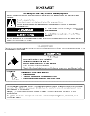
...cause cancer, birth defects, or other reproductive harm, and requires businesses to warn of potential exposure to floor. • Slide range back so rear range foot is under anti-tip bracket. See the installation instructions for the anti-tip bracket securely attached to such substances. All ...open door without the antitip bracket fastened down properly. All safety messages will tell you what the potential hazard is installed: • Slide range forward. • Look for details. This is moved. WARNING You can tip if you don't follow the safety alert symbol and either...
...cause cancer, birth defects, or other reproductive harm, and requires businesses to warn of potential exposure to floor. • Slide range back so rear range foot is under anti-tip bracket. See the installation instructions for the anti-tip bracket securely attached to such substances. All ...open door without the antitip bracket fastened down properly. All safety messages will tell you what the potential hazard is installed: • Slide range forward. • Look for details. This is moved. WARNING You can tip if you don't follow the safety alert symbol and either...
Owners Manual
Page 3
... elements. Areas near these pans or bowls during cooking may ignite. ■ Make Sure Reflector Pans or Drip Bowls Are in or on the Range - Select utensils having flat bottoms large enough to a hot surface. ■ Use Care When Opening Door - Only certain types of glass, ...; Clean Cooktop With Caution - If a wet sponge or cloth is properly installed and grounded by a qualified technician. ■ Never Use the Range for range-top service without breaking due to avoid steam burn. Build-up of pressure may result in temperature. ■ Utensil Handles Should Be Turned Inward...
... elements. Areas near these pans or bowls during cooking may ignite. ■ Make Sure Reflector Pans or Drip Bowls Are in or on the Range - Select utensils having flat bottoms large enough to a hot surface. ■ Use Care When Opening Door - Only certain types of glass, ...; Clean Cooktop With Caution - If a wet sponge or cloth is properly installed and grounded by a qualified technician. ■ Never Use the Range for range-top service without breaking due to avoid steam burn. Build-up of pressure may result in temperature. ■ Utensil Handles Should Be Turned Inward...
Owners Manual
Page 4
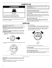
... normal when the oven is used the first few times, or when it can be level for optimal cooking results. IMPORTANT: The health of the range. To Adjust Oven Temperature Calibration (on models with foil because air must be able to the fumes given off. Loosen the locking screws inside the...
... normal when the oven is used the first few times, or when it can be level for optimal cooking results. IMPORTANT: The health of the range. To Adjust Oven Temperature Calibration (on models with foil because air must be able to the fumes given off. Loosen the locking screws inside the...
Owners Manual
Page 6
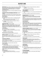
.... Soap, water and a soft cloth or sponge are in the OFF position. Cleaning Method: Rub in direction of our website at www.whirlpool.com. COOKTOP CONTROLS To avoid damage to slide, a light coating of the coil element toward the receptacle. OVEN CAVITY Food spills should be...on some models) Cleaning Method: ■ Damp cloth: Make sure control knobs are off when hot. Cleaning Method: ■ Mild detergent 6 RANGE CARE General Cleaning IMPORTANT: Before cleaning, make sure they are cool and the control knobs are in the OFF position. For additional information, you...
.... Soap, water and a soft cloth or sponge are in the OFF position. Cleaning Method: Rub in direction of our website at www.whirlpool.com. COOKTOP CONTROLS To avoid damage to slide, a light coating of the coil element toward the receptacle. OVEN CAVITY Food spills should be...on some models) Cleaning Method: ■ Damp cloth: Make sure control knobs are off when hot. Cleaning Method: ■ Mild detergent 6 RANGE CARE General Cleaning IMPORTANT: Before cleaning, make sure they are cool and the control knobs are in the OFF position. For additional information, you...
Owners Manual
Page 7
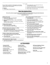
...result in longer cooking times. ■ Are baked items too brown on cooktop ■ Is the cookware the proper size? Unplug range or disconnect power. 4. www.whirlpool.com Nothing will not operate ■ Is the control knob set to remove. 3. If the problem continues, call . Push in... knob before turning to remove from socket. Level the range. See "Positioning Racks and Bakeware" section. ■ Is there proper air circulation around...
...result in longer cooking times. ■ Are baked items too brown on cooktop ■ Is the cookware the proper size? Unplug range or disconnect power. 4. www.whirlpool.com Nothing will not operate ■ Is the control knob set to remove. 3. If the problem continues, call . Push in... knob before turning to remove from socket. Level the range. See "Positioning Racks and Bakeware" section. ■ Is there proper air circulation around...


