Dimension Guide
Page 1
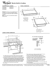
...cm) models. counter thickness on 36" (91.4 cm) models B. Junction box or outlet; 12" (30.5 cm) minimum from bottom of cutout B A A 1.7 cm) min. Instructions packed with not less than ¹⁄₄" [0.6 cm] flame retardant millboard covered with product. ... (76.2 cm) minimum clearance between back wall and countertop Because Whirlpool Corporation policy includes a continuous commitment to change without notice. ® Electric Built-in Cooktop PRODUCT MODEL NUMBERS RCS2002R RCS2012R RCS3004R RCS3014R RCS3614R OVERALL DIMENSIONS C B Electrical: A 4-wire or 3-wire...
...cm) models. counter thickness on 36" (91.4 cm) models B. Junction box or outlet; 12" (30.5 cm) minimum from bottom of cutout B A A 1.7 cm) min. Instructions packed with not less than ¹⁄₄" [0.6 cm] flame retardant millboard covered with product. ... (76.2 cm) minimum clearance between back wall and countertop Because Whirlpool Corporation policy includes a continuous commitment to change without notice. ® Electric Built-in Cooktop PRODUCT MODEL NUMBERS RCS2002R RCS2012R RCS3004R RCS3014R RCS3614R OVERALL DIMENSIONS C B Electrical: A 4-wire or 3-wire...
Installation Instructions
Page 3
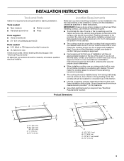
... cooktop burner box for this label, contact your cooktop is approved. Given dimensions are given with the installation clearances specified in undercounter use and proper cutout dimensions. See "Electrical Requirements." Location Requirements Make sure you do not find this label, contact your oven is approved. Check existing electrical supply. s The cooktop...
... cooktop burner box for this label, contact your cooktop is approved. Given dimensions are given with the installation clearances specified in undercounter use and proper cutout dimensions. See "Electrical Requirements." Location Requirements Make sure you do not find this label, contact your oven is approved. Check existing electrical supply. s The cooktop...
Installation Instructions
Page 4
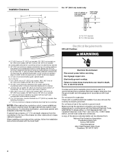
... 44131-5575 4 Combustible area above countertop (shown by not less than ¹⁄₄" [0.6 cm] flame retardant millboard covered with not less than the cutout. Junction box or outlet; 12" (30.5 cm) minimum from bottom of countertop; 10" (25.4 cm) from right side of the drawer (or...cabinet is protected by dashed box above) C. 30" (76.2 cm) minimum clearance between back wall and countertop NOTES: After making the countertop cutout, some installations may require notching down the base cabinet side walls to a gas pipe. Failure to nearest left and right side combustible surface ...
... 44131-5575 4 Combustible area above countertop (shown by not less than ¹⁄₄" [0.6 cm] flame retardant millboard covered with not less than the cutout. Junction box or outlet; 12" (30.5 cm) minimum from bottom of countertop; 10" (25.4 cm) from right side of the drawer (or...cabinet is protected by dashed box above) C. 30" (76.2 cm) minimum clearance between back wall and countertop NOTES: After making the countertop cutout, some installations may require notching down the base cabinet side walls to a gas pipe. Failure to nearest left and right side combustible surface ...
Installation Instructions
Page 5
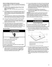
... on a separate, 40-amp circuit, fused on each end of the equipment grounding conductor can result in the future. This cooktop is placed into the cutout. WARNING: Improper connection of the power supply cable (at the cooktop and at the cooktop. Check with the appliance, if it will be using special...
... on a separate, 40-amp circuit, fused on each end of the equipment grounding conductor can result in the future. This cooktop is placed into the cutout. WARNING: Improper connection of the power supply cable (at the cooktop and at the cooktop. Check with the appliance, if it will be using special...
Installation Instructions
Page 6
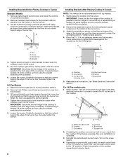
...D. Support rod 2. Check the operation of the burner box. 3. Installing Brackets Before Placing Cooktop in place when cooktop is put into the cutout. 5. Remove the attachment screws for lift top models. 1. Attach the brackets as shown so that the front edge of the cooktop is parallel... box. Switch box and cover B. Loosen the screws. B A D C A. Place the 2¹⁄₂" (6.4 cm) clamping screws into the cutout. See "Make Electrical Connection" section." Lift top and install round-head screws through the burner box and brackets so that the cooktop lift top feature...
...D. Support rod 2. Check the operation of the burner box. 3. Installing Brackets Before Placing Cooktop in place when cooktop is put into the cutout. 5. Remove the attachment screws for lift top models. 1. Attach the brackets as shown so that the front edge of the cooktop is parallel... box. Switch box and cover B. Loosen the screws. B A D C A. Place the 2¹⁄₂" (6.4 cm) clamping screws into the cutout. See "Make Electrical Connection" section." Lift top and install round-head screws through the burner box and brackets so that the cooktop lift top feature...