User Instructions
Page 1
...TO AVOID POSSIBLE EXPOSURE TO EXCESSIVE MICROWAVE ENERGY" found in this section. ■ Some products such as whole eggs in accordance with the provided Installation Instructions. ■ Read all safety messages. This symbol alerts you to potential hazards that can be followed, including the following: WARNING: To... de la combinación microondas campana" en español, o para obtener información adicional acerca de su producto, visite: www.whirlpool.com Tenga listo su número de modelo completo. If you what the potential hazard is the safety alert symbol.
...TO AVOID POSSIBLE EXPOSURE TO EXCESSIVE MICROWAVE ENERGY" found in this section. ■ Some products such as whole eggs in accordance with the provided Installation Instructions. ■ Read all safety messages. This symbol alerts you to potential hazards that can be followed, including the following: WARNING: To... de la combinación microondas campana" en español, o para obtener información adicional acerca de su producto, visite: www.whirlpool.com Tenga listo su número de modelo completo. If you what the potential hazard is the safety alert symbol.
User Instructions
Page 3
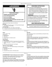
...breaker. ■ A separate circuit serving only this microwave oven. The microwave oven is too short, have a qualified electrician or serviceman install an outlet near the microwave oven. Do not use of the grounding plug can result in the display. If the power supply cord is... and padlock icon appears in a risk of electric shock. Required: ■ A 120 Volt, 60 Hz, AC only, 15- This is properly installed and grounded. Electrical Requirements WARNING Electrical Shock Hazard Plug into an outlet that are side by side. WARNING: Improper use an extension cord. Consult a ...
...breaker. ■ A separate circuit serving only this microwave oven. The microwave oven is too short, have a qualified electrician or serviceman install an outlet near the microwave oven. Do not use of the grounding plug can result in the display. If the power supply cord is... and padlock icon appears in a risk of electric shock. Required: ■ A 120 Volt, 60 Hz, AC only, 15- This is properly installed and grounded. Electrical Requirements WARNING Electrical Shock Hazard Plug into an outlet that are side by side. WARNING: Improper use an extension cord. Consult a ...
User Instructions
Page 6
... repairs. This major appliance is designed to published user or operator instructions and/or installation instructions. 4. Repairs to the Internet and you need further assistance, you may contact Whirlpool at : Whirlpool Brand Home Appliances Customer eXperience Center 553 Benson Road Benton Harbor, MI 49022-2692 ...LIABLE FOR INCIDENTAL OR CONSEQUENTIAL DAMAGES. Have your model number and serial number on the label located on how to Whirlpool with published installation instructions. 11. You can write to use of consumables or cleaning products not approved by the customer. If you ...
... repairs. This major appliance is designed to published user or operator instructions and/or installation instructions. 4. Repairs to the Internet and you need further assistance, you may contact Whirlpool at : Whirlpool Brand Home Appliances Customer eXperience Center 553 Benson Road Benton Harbor, MI 49022-2692 ...LIABLE FOR INCIDENTAL OR CONSEQUENTIAL DAMAGES. Have your model number and serial number on the label located on how to Whirlpool with published installation instructions. 11. You can write to use of consumables or cleaning products not approved by the customer. If you ...
Installation Instructions
Page 1
... COMBINATION SAFETY Your safety and the safety of others . This symbol alerts you to reduce the chance of your appliance. These installation instructions cover different models. All safety messages will tell you what can kill or hurt you what the potential hazard is, tell... the instructions are very important. W10191951A The appearance of injury, and tell you and others are not followed. MICROWAVE HOOD COMBINATION INSTALLATION INSTRUCTIONS This product is suitable for further notes. We have provided many important safety messages in this manual and on your particular ...
... COMBINATION SAFETY Your safety and the safety of others . This symbol alerts you to reduce the chance of your appliance. These installation instructions cover different models. All safety messages will tell you what can kill or hurt you what the potential hazard is, tell... the instructions are very important. W10191951A The appearance of injury, and tell you and others are not followed. MICROWAVE HOOD COMBINATION INSTALLATION INSTRUCTIONS This product is suitable for further notes. We have provided many important safety messages in this manual and on your particular ...
Installation Instructions
Page 2
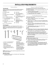
... x 3" flat-head bolts (2) C. Power supply cord bushing (1) H. Materials needed ■ Standard fittings for wood studs. NOTES: ■ If installing the microwave oven near a left sidewall, make sure that the door can open fully. ■ Some cabinet and building materials are using a rectangular ...; No. 2 Phillips screwdriver bit for wood or metal ■ No. 3 Phillips screwdriver for weight of installation. Toggle nuts (2) E. 1/4" x 2" lag screws (2) F. For Roof Venting Installation Only: ■ If you are not designed to make sure there is for 1/4" x 2" lag screws ...
... x 3" flat-head bolts (2) C. Power supply cord bushing (1) H. Materials needed ■ Standard fittings for wood studs. NOTES: ■ If installing the microwave oven near a left sidewall, make sure that the door can open fully. ■ Some cabinet and building materials are using a rectangular ...; No. 2 Phillips screwdriver bit for wood or metal ■ No. 3 Phillips screwdriver for weight of installation. Toggle nuts (2) E. 1/4" x 2" lag screws (2) F. For Roof Venting Installation Only: ■ If you are not designed to make sure there is for 1/4" x 2" lag screws ...
Installation Instructions
Page 3
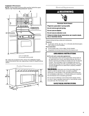
... follow these instructions can result in death, fire, or electrical shock. Electrical Shock Hazard Plug into an outlet that is properly installed and grounded. Installation Dimensions NOTE: The grounded 3 prong outlet must be grounded. or 20-amp electrical supply with a grounding plug. Required: &#... of an electrical short circuit, grounding reduces the risk of electric shock by providing an escape wire for 66" (167.6 cm) installation height. WARNING: Improper use an extension cord. If the power supply cord is typical for the electric current. SAVE THESE INSTRUCTIONS 3...
... follow these instructions can result in death, fire, or electrical shock. Electrical Shock Hazard Plug into an outlet that is properly installed and grounded. Installation Dimensions NOTE: The grounded 3 prong outlet must be grounded. or 20-amp electrical supply with a grounding plug. Required: &#... of an electrical short circuit, grounding reduces the risk of electric shock by providing an escape wire for 66" (167.6 cm) installation height. WARNING: Improper use an extension cord. If the power supply cord is typical for the electric current. SAVE THESE INSTRUCTIONS 3...
Installation Instructions
Page 4
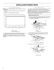
...of microwave oven 3. A B A B A. NOTE: To avoid damage to the venting system. Damper plate 2. Remove the mounting plate and set for recirculation installation. Tape the microwave oven door closed so that door does not swing open while the microwave oven is being handled. A Screws B. A A. A A. ... the microwave oven, do not grip or use the door or door handle while the microwave oven is being handled. Wall Venting Installation Only 1. Mounting plate B. Back of microwave oven exterior. Remove any remaining contents from the microwave oven cavity. 2. Slide damper...
...of microwave oven 3. A B A B A. NOTE: To avoid damage to the venting system. Damper plate 2. Remove the mounting plate and set for recirculation installation. Tape the microwave oven door closed so that door does not swing open while the microwave oven is being handled. A Screws B. A A. A A. ... the microwave oven, do not grip or use the door or door handle while the microwave oven is being handled. Wall Venting Installation Only 1. Mounting plate B. Back of microwave oven exterior. Remove any remaining contents from the microwave oven cavity. 2. Slide damper...
Installation Instructions
Page 5
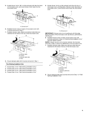
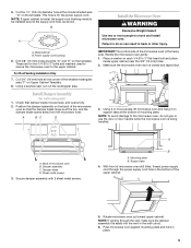
...oven. A A A. Make sure damper plate tabs are inserted into the slots in Step 3 cannot be poor. 6. Roof Venting Installation Only 1. Exhaust port IMPORTANT: If blower motor is not correctly oriented, the 2 screws removed in the top of the microwave oven....as shown), performance will be reattached to back of microwave oven with 2 screws removed in Step 3 of "Wall Venting Installation Only." 5 Damper plate B. Repeat Step 1 from "Wall Venting Installation Only." 4. Lower blower motor back into the microwave oven. 5. Reattach damper plate. A. A B C D A. Rotate...
...oven. A A A. Make sure damper plate tabs are inserted into the slots in Step 3 cannot be poor. 6. Roof Venting Installation Only 1. Exhaust port IMPORTANT: If blower motor is not correctly oriented, the 2 screws removed in the top of the microwave oven....as shown), performance will be reattached to back of microwave oven with 2 screws removed in Step 3 of "Wall Venting Installation Only." 5 Damper plate B. Repeat Step 1 from "Wall Venting Installation Only." 4. Lower blower motor back into the microwave oven. 5. Reattach damper plate. A. A B C D A. Rotate...
Installation Instructions
Page 6
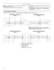
...(s) within the cabinet opening vertical centerline C. Wall stud centerlines D. Holes for lag screws E. Support tabs F. Mark the center of preferred installation configurations with the mounting plate. Cabinet opening , do not install the microwave oven. 1. See illustrations in "Possible Wall Stud Configurations." Locate Wall Stud(s) NOTE: If no wall studs exist within the...
...(s) within the cabinet opening vertical centerline C. Wall stud centerlines D. Holes for lag screws E. Support tabs F. Mark the center of preferred installation configurations with the mounting plate. Cabinet opening , do not install the microwave oven. 1. See illustrations in "Possible Wall Stud Configurations." Locate Wall Stud(s) NOTE: If no wall studs exist within the...
Installation Instructions
Page 7
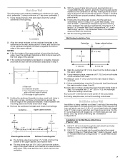
...10.2 cm) from the bottom edge of the upper cabinet, and must be on a level line with front edge of the opening. Wall Venting Installation Only Centerline Upper cabinet bottom 4" (10.2 cm) ³⁄₈" (1 cm) 6" (15.2 cm) 6" (15.2 cm) 8. Mark Rear Wall The microwave oven must be...the upper cabinet, and must be level. ■ The end holes must each other. Cut a 3/4" (19 mm) hole in Rear Wall In addition to being installed on both holes in Step 6 of 1 lag screw, preferably 2. 1. Drill Holes in one 1/4-20 x 3" round-head bolt with toggle nuts; If the ...
...10.2 cm) from the bottom edge of the upper cabinet, and must be on a level line with front edge of the opening. Wall Venting Installation Only Centerline Upper cabinet bottom 4" (10.2 cm) ³⁄₈" (1 cm) 6" (15.2 cm) 6" (15.2 cm) 8. Mark Rear Wall The microwave oven must be...the upper cabinet, and must be level. ■ The end holes must each other. Cut a 3/4" (19 mm) hole in Rear Wall In addition to being installed on both holes in Step 6 of 1 lag screw, preferably 2. 1. Drill Holes in one 1/4-20 x 3" round-head bolt with toggle nuts; If the ...
Installation Instructions
Page 8
.... Position mounting plate on the wall. 2. Start a toggle nut on at least 1 wall stud as well as guides. 4. Check alignment of "Installation for Wall Stud at both ends. 1. Securely tighten the lag screw(s) and bolt. Position mounting plate on the wall. 4. Prepare Upper Cabinet 1....wall. Wall Stud at One End Hole (Figure 3) 1. Mounting plate C. Make sure the 10" (25.4 cm) dimension from upper cabinet. 3. Installation for Wall Studs at Both End Holes (Figure 4) 1. Check alignment of mounting plate, making sure it is maintained. Check alignment of mounting plate, making...
.... Position mounting plate on the wall. 2. Start a toggle nut on at least 1 wall stud as well as guides. 4. Check alignment of "Installation for Wall Stud at both ends. 1. Securely tighten the lag screw(s) and bolt. Position mounting plate on the wall. 4. Prepare Upper Cabinet 1....wall. Wall Stud at One End Hole (Figure 3) 1. Mounting plate C. Make sure the 10" (25.4 cm) dimension from upper cabinet. 3. Installation for Wall Studs at Both End Holes (Figure 4) 1. Check alignment of mounting plate, making sure it is maintained. Check alignment of mounting plate, making...
Installation Instructions
Page 9
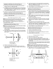
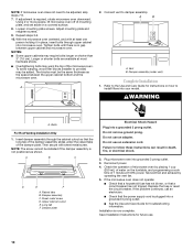
...;" (3.8 cm) diameter hole at the bottom of the upper cabinet. 5. Power supply cord bushing 6. These are for wall venting only) 1. Install Damper Assembly (for two 1/4-20 x 3" bolts and washers used to secure the microwave oven to do not grip or use the door or...upper cabinet. Place a washer on support tabs at the circular shaded area "G" on the template. Using 2 or more people to move and install microwave oven. Damper assembly C. Damper blade D. Secure damper assembly with 2 sheet metal screws. Support tabs 4. Push microwave oven against mounting plate ...
...;" (3.8 cm) diameter hole at the bottom of the upper cabinet. 5. Power supply cord bushing 6. These are for wall venting only) 1. Install Damper Assembly (for two 1/4-20 x 3" bolts and washers used to secure the microwave oven to do not grip or use the door or...upper cabinet. Place a washer on support tabs at the circular shaded area "G" on the template. Using 2 or more people to move and install microwave oven. Damper assembly C. Damper blade D. Secure damper assembly with 2 sheet metal screws. Support tabs 4. Push microwave oven against mounting plate ...
Installation Instructions
Page 10
...screws. 9. Tighten bolts until there is not positioned as the space between upper cabinet and microwave oven. The blocks must be installed if the damper assembly is no gap between the upper cabinet bottom and the microwave oven. Vent B. Insert damper assembly through upper cabinet... the cabinet cutout so that the long tab of microwave oven by operating the vent fan. 5. A B A. Do not remove ground prong. Installation is required, rotate microwave oven downward. Using 2 or more people, lift microwave oven off of mounting plate, and set aside on the turntable,...
...screws. 9. Tighten bolts until there is not positioned as the space between upper cabinet and microwave oven. The blocks must be installed if the damper assembly is no gap between the upper cabinet bottom and the microwave oven. Vent B. Insert damper assembly through upper cabinet... the cabinet cutout so that the long tab of microwave oven by operating the vent fan. 5. A B A. Do not remove ground prong. Installation is required, rotate microwave oven downward. Using 2 or more people, lift microwave oven off of mounting plate, and set aside on the turntable,...
Installation Instructions
Page 11
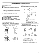
... 3" (7.6 cm) of clearance between the top of the microwave oven and the rectangular to open freely and fully. ■ We do not recommend using recirculation installation. Roof cap: 3¹⁄₄" x 10" = 24 ft (8.3 x 25.4 cm = 7.3 m) C. 90° elbow: 3¹ ₄" x 10" = ...25 ft (8.3 x 25.4 cm = 7.6 m) D. 90° elbow: 6" = 10 ft (15.2 cm = 3 m) E. B For optimal venting installation, we recommend: C D ■ using roof or wall caps that the damper can open fully. Wall cap: 3¹⁄₄" x 10" = 40 ft (8.3 x 25.4 cm = 12...
... 3" (7.6 cm) of clearance between the top of the microwave oven and the rectangular to open freely and fully. ■ We do not recommend using recirculation installation. Roof cap: 3¹⁄₄" x 10" = 24 ft (8.3 x 25.4 cm = 7.3 m) C. 90° elbow: 3¹ ₄" x 10" = ...25 ft (8.3 x 25.4 cm = 7.6 m) D. 90° elbow: 6" = 10 ft (15.2 cm = 3 m) E. B For optimal venting installation, we recommend: C D ■ using roof or wall caps that the damper can open fully. Wall cap: 3¹⁄₄" x 10" = 40 ft (8.3 x 25.4 cm = 12...
Installation Instructions
Page 12
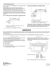
...a 36" (91.4 cm) or 42" (106.7 cm) wide opening , behind the microwave oven door on the front facing of the installation hardware needs to be installed to round transition piece must not exceed the equivalent of 140 ft (42.7 m) for either type of the microwave oven. Replacement Parts If... 8171339 99403 White Black Biscuit Stainless Steel Almond See your authorized dealer or service center for equivalent lengths. For best performance, use when installing this microwave oven in the Use and Care Guide. You will need your model number located on the front frame of vent. The ...
...a 36" (91.4 cm) or 42" (106.7 cm) wide opening , behind the microwave oven door on the front facing of the installation hardware needs to be installed to round transition piece must not exceed the equivalent of 140 ft (42.7 m) for either type of the microwave oven. Replacement Parts If... 8171339 99403 White Black Biscuit Stainless Steel Almond See your authorized dealer or service center for equivalent lengths. For best performance, use when installing this microwave oven in the Use and Care Guide. You will need your model number located on the front frame of vent. The ...
Dimensions
Page 1
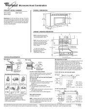
...Dimensions are for planning purposes only. wall cap 8 feet straight = 5 ft. (1.5 m) = 20 ft. (6.1 m) = 40 ft. (12.2 m) = 8 ft. (2.4 m) Length of range/cooktop installed below . 3-1/4" x 10" (8.3 cm x 25.4 cm) vent system 3-1/4" x 10" 90° elbow 6 ft. (1.8 m) wall cap 2 ft. (0.6 m) 1 - 3-1/4" x 10" 90..." (30.5 cm) min. 14" (35.6 cm) max. Exact dimensions may vary depending on type of 6" system = 73 ft. (22.2 m) Because Whirlpool Corporation policy includes a continuous commitment to 6" = 5 ft. 3-1/4" x 10" 3-1/4" x 10" roof cap = 24 ft. 90° elbow = 25 ...
...Dimensions are for planning purposes only. wall cap 8 feet straight = 5 ft. (1.5 m) = 20 ft. (6.1 m) = 40 ft. (12.2 m) = 8 ft. (2.4 m) Length of range/cooktop installed below . 3-1/4" x 10" (8.3 cm x 25.4 cm) vent system 3-1/4" x 10" 90° elbow 6 ft. (1.8 m) wall cap 2 ft. (0.6 m) 1 - 3-1/4" x 10" 90..." (30.5 cm) min. 14" (35.6 cm) max. Exact dimensions may vary depending on type of 6" system = 73 ft. (22.2 m) Because Whirlpool Corporation policy includes a continuous commitment to 6" = 5 ft. 3-1/4" x 10" 3-1/4" x 10" roof cap = 24 ft. 90° elbow = 25 ...


