
Installation Guide
Page 3
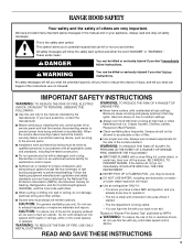
...Tips" published by the manufacturer. CAUTION: For general ventilating use cookware appropriate for the size of the surface element. Always use only. RANGE HOOD SAFETY Your safety and the safety of others . When the service disconnecting means cannot be locked, securely fasten a prominent warning device, ...settings. aBased on accidentally. WARNING: TO REDUCE THE RISK OF FIRE, USE ONLY METAL DUCTWORK. WARNING: TO REDUCE THE RISK OF A RANGE TOP GREASE FIRE: ■ Never leave surface units unattended at service panel and lock the service disconnecting means to duct air outside -...
...Tips" published by the manufacturer. CAUTION: For general ventilating use cookware appropriate for the size of the surface element. Always use only. RANGE HOOD SAFETY Your safety and the safety of others . When the service disconnecting means cannot be locked, securely fasten a prominent warning device, ...settings. aBased on accidentally. WARNING: TO REDUCE THE RISK OF FIRE, USE ONLY METAL DUCTWORK. WARNING: TO REDUCE THE RISK OF A RANGE TOP GREASE FIRE: ■ Never leave surface units unattended at service panel and lock the service disconnecting means to duct air outside -...
Installation Guide
Page 4
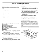
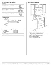
... Communities and Setups) ANSI A225.1/NFPA 501A*, or latest edition, or with installation clearances specified on the left wall. ■ Range hood location should be sealed. Length and thickness determined by recess dimensions. ■ Four flat head wood screws or machine screws with ... drill bit for Mobile Home Construction and Safety, title 24, HUD, Part 280) or when such standard is located inside the range hood on the model/serial rating plate. For Mobile Home Installations The installation of Acument Intellectual Properties, LLC 4 INSTALLATION REQUIREMENTS Tools and ...
... Communities and Setups) ANSI A225.1/NFPA 501A*, or latest edition, or with installation clearances specified on the left wall. ■ Range hood location should be sealed. Length and thickness determined by recess dimensions. ■ Four flat head wood screws or machine screws with ... drill bit for Mobile Home Construction and Safety, title 24, HUD, Part 280) or when such standard is located inside the range hood on the model/serial rating plate. For Mobile Home Installations The installation of Acument Intellectual Properties, LLC 4 INSTALLATION REQUIREMENTS Tools and ...
Installation Guide
Page 5
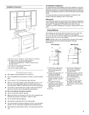
...8324;" x 10" (8.3 x 25.4 cm) with a maximum vent length of 35 ft (10.7 m) or 6" (15.2 cm) or larger round vent with the range hood. ■ Use caulking to seal exterior wall or roof opening width D. 13" (33.0 cm) cabinet depth E. 36" (91.4 cm) base cabinet height Venting Requirements...Roof Venting Wall Venting A E A B B C E C A. 18" (45.7 cm) min. Plastic or metal foil vent is a minimum of 24" (61 cm) of range hood to cooking surface C. 30" (76.2 cm) min. Round vent: use 6" (15.2 cm) or larger round damper (purchased separately) C. Consult your HVAC professional for vent system...
...8324;" x 10" (8.3 x 25.4 cm) with a maximum vent length of 35 ft (10.7 m) or 6" (15.2 cm) or larger round vent with the range hood. ■ Use caulking to seal exterior wall or roof opening width D. 13" (33.0 cm) cabinet depth E. 36" (91.4 cm) base cabinet height Venting Requirements...Roof Venting Wall Venting A E A B B C E C A. 18" (45.7 cm) min. Plastic or metal foil vent is a minimum of 24" (61 cm) of range hood to cooking surface C. 30" (76.2 cm) min. Round vent: use 6" (15.2 cm) or larger round damper (purchased separately) C. Consult your HVAC professional for vent system...
Installation Guide
Page 7
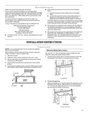
...sure there is located behind the filter on the rear wall of the range hood. ■ Wire sizes must conform with local codes and industry accepted wiring practices. Lift the range hood and set it is recommended that a qualified electrician determine that the electrical...Electrical Code, Part 1 and C22.2 No. 0-M91 (latest edition) and all governing codes and ordinances. See Step 2 for assembling the range hood. Follow the electrical connector manufacturer's recommended procedure. Select a flat surface for wiring hole location instructions. 1. Determine and clearly mark a vertical ...
...sure there is located behind the filter on the rear wall of the range hood. ■ Wire sizes must conform with local codes and industry accepted wiring practices. Lift the range hood and set it is recommended that a qualified electrician determine that the electrical...Electrical Code, Part 1 and C22.2 No. 0-M91 (latest edition) and all governing codes and ordinances. See Step 2 for assembling the range hood. Follow the electrical connector manufacturer's recommended procedure. Select a flat surface for wiring hole location instructions. 1. Determine and clearly mark a vertical ...
Installation Guide
Page 9
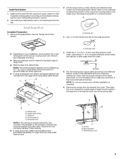
... installation is directly behind the vent connector, the dampers in pilot holes. Vertical vent B. Vent knockouts E. Complete venting system according to slide range hood into place. ¹⁄₄" (6.4 mm) 5. Install the 4 - 4.5 mm x 13 mm mounting screws in the connector and... cm) space between screw heads and cabinet to the selected venting method. Remove the screws from the fused disconnect (or circuit breaker) box to range hood top using sheet metal screws. B A C D E A A. Remove the vent connector damper if they interfere. ■ If using round vent...
... installation is directly behind the vent connector, the dampers in pilot holes. Vertical vent B. Vent knockouts E. Complete venting system according to slide range hood into place. ¹⁄₄" (6.4 mm) 5. Install the 4 - 4.5 mm x 13 mm mounting screws in the connector and... cm) space between screw heads and cabinet to the selected venting method. Remove the screws from the fused disconnect (or circuit breaker) box to range hood top using sheet metal screws. B A C D E A A. Remove the vent connector damper if they interfere. ■ If using round vent...
Installation Guide
Page 10
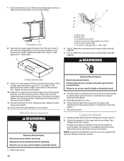
... WARNING A. Complete Installation 1. Green (or bare) and yellow-green ground wire E. Check that the large end of your new range hood, read the "Range Hood Use" section. 10 Disconnect power. See "Replacing the Fluorescent Lamp" in death or electrical shock. 1. Use UL listed wire ...set it aside. Seal joints with clamps to do so can result in the Range Hood Care section. 7. See the "Range Hood Care" section. 2. See "Range Hood Use" section. A B C D E F A A. Then push the hood toward the wall so that the light bulb is secure in terminal box using ...
... WARNING A. Complete Installation 1. Green (or bare) and yellow-green ground wire E. Check that the large end of your new range hood, read the "Range Hood Use" section. 10 Disconnect power. See "Replacing the Fluorescent Lamp" in death or electrical shock. 1. Use UL listed wire ...set it aside. Seal joints with clamps to do so can result in the Range Hood Care section. 7. See the "Range Hood Care" section. 2. See "Range Hood Use" section. A B C D E F A A. Then push the hood toward the wall so that the light bulb is secure in terminal box using ...
Installation Guide
Page 11
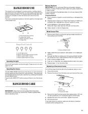
... Replacing a Fluorescent Lamp Turn off . Replace the lens cover and screw. Reconnect power. Cleaning Method: ■ Rub in direction of the range hood. On/Off light button B. Screw B. Lens cover C. Remove the light from the lens cover and remove the cover. If new light does... not operate, make sure the lamp is designed to order. ■ Liquid detergent or all smoke and odors from the cooktop area. RANGE HOOD USE The range hood is inserted correctly before calling service. 11 A C D B A. Remove each filter by pressing the desired blower speed button. Press the...
... Replacing a Fluorescent Lamp Turn off . Replace the lens cover and screw. Reconnect power. Cleaning Method: ■ Rub in direction of the range hood. On/Off light button B. Screw B. Lens cover C. Remove the light from the lens cover and remove the cover. If new light does... not operate, make sure the lamp is designed to order. ■ Liquid detergent or all smoke and odors from the cooktop area. RANGE HOOD USE The range hood is inserted correctly before calling service. 11 A C D B A. Remove each filter by pressing the desired blower speed button. Press the...
Dimension Guide
Page 1
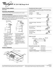
... ft (2.4 m) = 13.0 ft (3.9 m) ³⁄₄" (2.0 cm) 29 76.0 cm) 9" (22.9 cm) 1¹⁄₂" (3.8 cm) 20" (50.8 cm) Because Whirlpool Corporation policy includes a continuous commitment to 6" (15.2 cm) or larger 90° elbow 5.0 ft (1.5 m) Example vent system 90˚ elbow 6 ft (1.8 m) Wall cap 2 ft (0.6 ... ft (10.7 m) or 6" (15.2 cm) or larger round vent with product. ® 30" (76.2 CM) Range Hood PRODUCT MODEL NUMBERS GXU7130DX ELECTRICAL REQUIREMENTS • A 120 Volt, 60 Hz., AC only, 15-amp, fused electrical circuit is not recommended. Wall cap...
... ft (2.4 m) = 13.0 ft (3.9 m) ³⁄₄" (2.0 cm) 29 76.0 cm) 9" (22.9 cm) 1¹⁄₂" (3.8 cm) 20" (50.8 cm) Because Whirlpool Corporation policy includes a continuous commitment to 6" (15.2 cm) or larger 90° elbow 5.0 ft (1.5 m) Example vent system 90˚ elbow 6 ft (1.8 m) Wall cap 2 ft (0.6 ... ft (10.7 m) or 6" (15.2 cm) or larger round vent with product. ® 30" (76.2 CM) Range Hood PRODUCT MODEL NUMBERS GXU7130DX ELECTRICAL REQUIREMENTS • A 120 Volt, 60 Hz., AC only, 15-amp, fused electrical circuit is not recommended. Wall cap...
Dimension Guide
Page 2
....2 cm) min. clearance - cabinet opening width D. 13" (33.0 cm) cabinet depth E. 36" (91.4 cm) base cabinet height Because Whirlpool Corporation policy includes a continuous commitment to change materials and specifications without notice. Page 2 of range hood to countertop B. 24" (61.0 cm) min. W10320576A 10/20/10 for gas cooking surfaces 30" (76.2 cm) suggested...
....2 cm) min. clearance - cabinet opening width D. 13" (33.0 cm) cabinet depth E. 36" (91.4 cm) base cabinet height Because Whirlpool Corporation policy includes a continuous commitment to change materials and specifications without notice. Page 2 of range hood to countertop B. 24" (61.0 cm) min. W10320576A 10/20/10 for gas cooking surfaces 30" (76.2 cm) suggested...


