

Warranty Information
Page 1
... borne by calling Whirlpool. Write down the following information about your major appliance, to replace or repair house fuses, or to obtain service under these excluded circumstances shall be repaired in the home and only in accordance with original model/serial numbers that is used for future reference. Proof of the Use & Care Guide. Damage resulting from warranty coverage. 3. THIS WARRANTY GIVES YOU SPECIFIC LEGAL RIGHTS...
... borne by calling Whirlpool. Write down the following information about your major appliance, to replace or repair house fuses, or to obtain service under these excluded circumstances shall be repaired in the home and only in accordance with original model/serial numbers that is used for future reference. Proof of the Use & Care Guide. Damage resulting from warranty coverage. 3. THIS WARRANTY GIVES YOU SPECIFIC LEGAL RIGHTS...
Installation Guide
Page 3
... wall or ceiling; RANGE HOOD SAFETY Your safety and the safety of others . Always read and obey all applicable codes and standards, including fire-rated construction. ■ Do not operate any solid-state speed control device. This symbol alerts you have questions, contact the manufacturer. ■ Before servicing or cleaning the unit, switch power off the burner. aBased on fan or filter. ■ Use proper pan size. Discard fan...
... wall or ceiling; RANGE HOOD SAFETY Your safety and the safety of others . Always read and obey all applicable codes and standards, including fire-rated construction. ■ Do not operate any solid-state speed control device. This symbol alerts you have questions, contact the manufacturer. ■ Before servicing or cleaning the unit, switch power off the burner. aBased on fan or filter. ■ Use proper pan size. Discard fan...
Installation Guide
Page 4
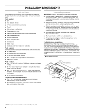
... - Given dimensions provide minimum clearance. For Mobile Home Installations The installation of Acument Intellectual Properties, LLC 4 Consult the cooktop/range manufacturer installation instructions before starting installation. Check that all governing codes and ordinances. ■ It is the installer's responsibility to attach filler strips). UL listed wire connectors For cabinets with any cutouts. ■ Grounded electrical outlet is required. See "Electrical Requirements" section. ■ The hood is factory-set for Manufactured Home Installation 1982 (Manufactured...
... - Given dimensions provide minimum clearance. For Mobile Home Installations The installation of Acument Intellectual Properties, LLC 4 Consult the cooktop/range manufacturer installation instructions before starting installation. Check that all governing codes and ordinances. ■ It is the installer's responsibility to attach filler strips). UL listed wire connectors For cabinets with any cutouts. ■ Grounded electrical outlet is required. See "Electrical Requirements" section. ■ The hood is factory-set for Manufactured Home Installation 1982 (Manufactured...
Installation Guide
Page 5
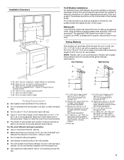
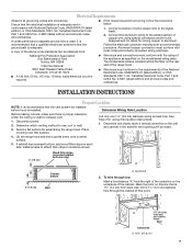
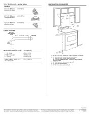
... exterior wall or roof opening width D. 13" (33.0 cm) cabinet depth E. 36" (91.4 cm) base cabinet height Venting Requirements ■ Vent system must have a damper. NOTE: Flexible vent is recommended. Round vent: use 3¹⁄₄" x 10" (8.3 x 25.4 cm) to 6" (15.2 cm) or larger diameter transition piece (purchased separately) D. 27" (68.6 cm) - 30" (76.2 cm) above gas cooking surface 24" (61.0 cm) - 30" (76.2 cm) above electric cooking surface E. Installation Clearances...
... exterior wall or roof opening width D. 13" (33.0 cm) cabinet depth E. 36" (91.4 cm) base cabinet height Venting Requirements ■ Vent system must have a damper. NOTE: Flexible vent is recommended. Round vent: use 3¹⁄₄" x 10" (8.3 x 25.4 cm) to 6" (15.2 cm) or larger diameter transition piece (purchased separately) D. 27" (68.6 cm) - 30" (76.2 cm) above gas cooking surface 24" (61.0 cm) - 30" (76.2 cm) above electric cooking surface E. Installation Clearances...
Installation Guide
Page 6
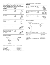
wall cap Length of the system you need, add the equivalent feet (meters) for each vent piece used in the system. 6" (15.2 cm) or Larger Round Vent System Vent Piece Round 45° elbow 2.5 ft (0.8 m) 3¹⁄₄" x 10" (8.3 cm x 25.4 cm) Vent System Vent Piece 3¹⁄₄" x 10" (8.3 cm x 25.4 cm) 5.0 ft 90° elbow (1.5 m) 3¹⁄₄" x 10" (8.3 cm x 25.4 cm) 12...
wall cap Length of the system you need, add the equivalent feet (meters) for each vent piece used in the system. 6" (15.2 cm) or Larger Round Vent System Vent Piece Round 45° elbow 2.5 ft (0.8 m) 3¹⁄₄" x 10" (8.3 cm x 25.4 cm) Vent System Vent Piece 3¹⁄₄" x 10" (8.3 cm x 25.4 cm) 5.0 ft 90° elbow (1.5 m) 3¹⁄₄" x 10" (8.3 cm x 25.4 cm) 12...
Installation Guide
Page 7
... recommended that the electrical installation is used, it upside down onto covered surface. 5. Determine Wiring Hole Location Before making cutouts, make sure there is adequate. See Step 2 for exhaust vent. 1. Lift the range hood and set it is recommended that a qualified electrician determine that surface. To wire through the cabinet at this line that is located behind the filter on the rear wall of the National Electrical Code, ANSI/NFPA...
... recommended that the electrical installation is used, it upside down onto covered surface. 5. Determine Wiring Hole Location Before making cutouts, make sure there is adequate. See Step 2 for exhaust vent. 1. Lift the range hood and set it is recommended that a qualified electrician determine that surface. To wire through the cabinet at this line that is located behind the filter on the rear wall of the National Electrical Code, ANSI/NFPA...
Installation Guide
Page 8
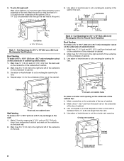
... a 1¹⁄₄" (3.2 cm) diameter hole through wall: Mark a line distance "A" from the back wall on the back wall. 2. Circular vent opening on the underside of cabinet. 2. Mark the point on this point. 3. Mark lines 5¼" (13.3 cm) to Round Vent Transition Roof Venting To make a circular vent opening *5" (12.7 cm) Cabinet cutouts *From wall, not cabinet frame 8 Mark a line 5" (12.7 cm) from the underside of...
... a 1¹⁄₄" (3.2 cm) diameter hole through wall: Mark a line distance "A" from the back wall on the back wall. 2. Circular vent opening on the underside of cabinet. 2. Mark the point on this point. 3. Mark lines 5¼" (13.3 cm) to Round Vent Transition Roof Venting To make a circular vent opening *5" (12.7 cm) Cabinet cutouts *From wall, not cabinet frame 8 Mark a line 5" (12.7 cm) from the underside of...
Installation Guide
Page 9
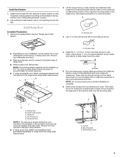
... enough wiring from the terminal box cover. Leave about ¹⁄₄" (6.4 cm) space between screw heads and cabinet to the selected venting method. Run the home power supply cable according to seal exterior wall or roof opening in pilot holes. Terminal box cover 9 Install Vent System 1. Use caulking to the National Electric Code or CSA standards and local codes and ordinances. See the "Range Hood Care" section. 2. Sheet metal screws C. If using sheet metal screws. Vertical vent B. Mounting...
... enough wiring from the terminal box cover. Leave about ¹⁄₄" (6.4 cm) space between screw heads and cabinet to the selected venting method. Run the home power supply cable according to seal exterior wall or roof opening in pilot holes. Terminal box cover 9 Install Vent System 1. Use caulking to the National Electric Code or CSA standards and local codes and ordinances. See the "Range Hood Care" section. 2. Sheet metal screws C. If using sheet metal screws. Vertical vent B. Mounting...
Installation Guide
Page 10
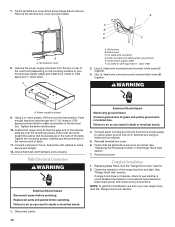
... the mounting screws. Electrical Shock Hazard Electrically ground blower. Connect ground wire to yellow-green ground wire (C) in the narrow neck of the range hood fan and light. Disconnect power and check wiring connections. Terminal box cover 8. Use UL listed wire connectors and connect white wires (A) together. 3. Tighten the mounting screws, making sure the screws are in death or electrical shock. 1. Replace all parts and panels before servicing. Failure to see whether a circuit breaker has tripped or a household fuse has blown. If range hood does not operate...
... the mounting screws. Electrical Shock Hazard Electrically ground blower. Connect ground wire to yellow-green ground wire (C) in the narrow neck of the range hood fan and light. Disconnect power and check wiring connections. Terminal box cover 8. Use UL listed wire connectors and connect white wires (A) together. 3. Tighten the mounting screws, making sure the screws are in death or electrical shock. 1. Replace all parts and panels before servicing. Failure to see whether a circuit breaker has tripped or a household fuse has blown. If range hood does not operate...
Installation Guide
Page 11
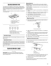
...-free cloth. ■ Glass cleaner to remove smoke, cooking vapors and odors from the lens cover and remove the cover. Disconnect power. 2. Fluorescent lamp 3. For best results, start the hood before operating hood. Remove the screw from the cooktop area. C A B A. If new light does not operate, make sure the lamp is designed to remove fingerprints. The hood controls are toward the front. Metal Grease Filter 1. Blower speed maximum button Operating the light The On/Off light button controls the light. Spring release handle 2. Replacing a Fluorescent Lamp Turn...
...-free cloth. ■ Glass cleaner to remove smoke, cooking vapors and odors from the lens cover and remove the cover. Disconnect power. 2. Fluorescent lamp 3. For best results, start the hood before operating hood. Remove the screw from the cooktop area. C A B A. If new light does not operate, make sure the lamp is designed to remove fingerprints. The hood controls are toward the front. Metal Grease Filter 1. Blower speed maximum button Operating the light The On/Off light button controls the light. Spring release handle 2. Replacing a Fluorescent Lamp Turn...
Installation Guide
Page 12
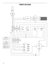
Black 56.5 Motor Characteristics Power Supply 120 VAC Frequency 60 Hz Power Absorption 144 Watts Current 1.2 A W R BR Y GY R BK BK 123 4567 GND Chassis GND Electrical Support GY R BK 1234 56 BK GY R Y BR 32 4 R BK 25 uF 15 uF Y/G R BK S30 L 1 BU 12 uF W 12 W Y/G WIRING DIAGRAM N GND L B K EMI Filter BK R W R BK Ballast BU BU W Y/G Y/G BK BK BK W Y/G Motor Resistance (Ohms) Red -
Black 56.5 Motor Characteristics Power Supply 120 VAC Frequency 60 Hz Power Absorption 144 Watts Current 1.2 A W R BR Y GY R BK BK 123 4567 GND Chassis GND Electrical Support GY R BK 1234 56 BK GY R Y BR 32 4 R BK 25 uF 15 uF Y/G R BK S30 L 1 BU 12 uF W 12 W Y/G WIRING DIAGRAM N GND L B K EMI Filter BK R W R BK Ballast BU BU W Y/G Y/G BK BK BK W Y/G Motor Resistance (Ohms) Red -
Installation Guide
Page 13
...; Features and specifications on our full line of appliances. ■ Installation information. ■ Use and maintenance procedures. ■ Accessory and repair parts sales. ■ Specialized customer assistance (Spanish speaking, hearing impaired, limited vision, etc.). ■ Referrals to local dealers, repair parts distributors, and service companies. Whirlpool Canada LP designated service technicians are made with the same precision used to fulfill the product warranty and provide after-warranty service, anywhere...
...; Features and specifications on our full line of appliances. ■ Installation information. ■ Use and maintenance procedures. ■ Accessory and repair parts sales. ■ Specialized customer assistance (Spanish speaking, hearing impaired, limited vision, etc.). ■ Referrals to local dealers, repair parts distributors, and service companies. Whirlpool Canada LP designated service technicians are made with the same precision used to fulfill the product warranty and provide after-warranty service, anywhere...
Installation Guide
Page 14
... is used for in accordance with original model/serial numbers that is contrary to published user or operator instructions and/or installation instructions. 4. Expenses for travel and transportation for Factory Specified Parts and repair labor to correct defects in a remote area where service by an authorized Whirlpool servicer is not available. 10. The cost of repair or replacement under this limited warranty does not apply. WHIRLPOOL CORPORATION MAJOR APPLIANCE WARRANTY LIMITED WARRANTY For...
... is used for in accordance with original model/serial numbers that is contrary to published user or operator instructions and/or installation instructions. 4. Expenses for travel and transportation for Factory Specified Parts and repair labor to correct defects in a remote area where service by an authorized Whirlpool servicer is not available. 10. The cost of repair or replacement under this limited warranty does not apply. WHIRLPOOL CORPORATION MAJOR APPLIANCE WARRANTY LIMITED WARRANTY For...
Dimension Guide
Page 1
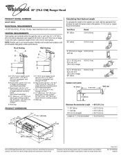
...) Because Whirlpool Corporation policy includes a continuous commitment to 6" (15.2 cm) or larger 90° elbow 5.0 ft (1.5 m) Example vent system 90˚ elbow 6 ft (1.8 m) Wall cap 2 ft (0.6 m) Maximum Recommended Length 1 - 90° elbow 1 - wall cap 8 ft (2.4 m) straight Length of 2 Ref. ® 30" (76.2 CM) Range Hood PRODUCT MODEL NUMBERS GXU7130DX ELECTRICAL REQUIREMENTS • A 120 Volt, 60 Hz., AC only, 15-amp, fused electrical circuit is not recommended. NOTE: Flexible vent is required. Flexible vent creates...
...) Because Whirlpool Corporation policy includes a continuous commitment to 6" (15.2 cm) or larger 90° elbow 5.0 ft (1.5 m) Example vent system 90˚ elbow 6 ft (1.8 m) Wall cap 2 ft (0.6 m) Maximum Recommended Length 1 - 90° elbow 1 - wall cap 8 ft (2.4 m) straight Length of 2 Ref. ® 30" (76.2 CM) Range Hood PRODUCT MODEL NUMBERS GXU7130DX ELECTRICAL REQUIREMENTS • A 120 Volt, 60 Hz., AC only, 15-amp, fused electrical circuit is not recommended. NOTE: Flexible vent is required. Flexible vent creates...
Dimension Guide
Page 2
...) elbow 6 ft (1.8 m) Wall cap 2 ft (0.6 m) Maximum Recommended Length = 35 ft (10.7 m) 1 - 90° elbow 8 ft (2.4 m) straight 1 - for electric cooking surfaces 27" (68.6 cm) min. Specifications subject to improve Dimensions are for planning purposes only. Page 2 of 3¹⁄₄" x 10" (8.3 cm x 25.4 cm) system = 13.0 ft (3.9 m) INSTALLATION CLEARANCES C B D A E A. 18" (45.7 cm) min. wall cap = 5.0 ft (1.5 m) = 8.0 ft (2.4 m) = 0.0 ft (0.0 m) Length of 2 Ref. bottom of range hood to cooking surface...
...) elbow 6 ft (1.8 m) Wall cap 2 ft (0.6 m) Maximum Recommended Length = 35 ft (10.7 m) 1 - 90° elbow 8 ft (2.4 m) straight 1 - for electric cooking surfaces 27" (68.6 cm) min. Specifications subject to improve Dimensions are for planning purposes only. Page 2 of 3¹⁄₄" x 10" (8.3 cm x 25.4 cm) system = 13.0 ft (3.9 m) INSTALLATION CLEARANCES C B D A E A. 18" (45.7 cm) min. wall cap = 5.0 ft (1.5 m) = 8.0 ft (2.4 m) = 0.0 ft (0.0 m) Length of 2 Ref. bottom of range hood to cooking surface...


