Use and Care Guide
Page 2
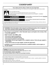
... followed. 2 WARNING You can happen if the instructions are very important. This symbol alerts you to reduce the chance of others . TABLE OF CONTENTS COOKTOP SAFETY 2 PARTS AND FEATURES 4 COOKTOP USE 7 Cooktop Controls 7 Sealed Surface Burners 7 Surface Grates with Locator Pin 8 Home Canning 8 Cookware 8 COOKTOP CARE 9 General Cleaning 9 TROUBLESHOOTING 10 ASSISTANCE OR SERVICE 11 In the U.S.A 11 Accessories 11 In Canada 11 WARRANTY 12 TABLE DES MATIÈRES SÉCURIT...
... followed. 2 WARNING You can happen if the instructions are very important. This symbol alerts you to reduce the chance of others . TABLE OF CONTENTS COOKTOP SAFETY 2 PARTS AND FEATURES 4 COOKTOP USE 7 Cooktop Controls 7 Sealed Surface Burners 7 Surface Grates with Locator Pin 8 Home Canning 8 Cookware 8 COOKTOP CARE 9 General Cleaning 9 TROUBLESHOOTING 10 ASSISTANCE OR SERVICE 11 In the U.S.A 11 Accessories 11 In Canada 11 WARRANTY 12 TABLE DES MATIÈRES SÉCURIT...
Use and Care Guide
Page 3
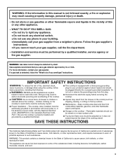
... not try to warn of this appliance as stepping, leaning, or sitting on or near surface units. ■ Top burner flame size should be performed by smell. IMPORTANT SAFETY INSTRUCTIONS WARNING: To reduce the risk of local codes, with the National Electrical Code, ANSI/NFPA70 or the Canadian Electrical Code, Part 1. The cooktop, when installed, must be adjusted so it does not extend beyond the...
... not try to warn of this appliance as stepping, leaning, or sitting on or near surface units. ■ Top burner flame size should be performed by smell. IMPORTANT SAFETY INSTRUCTIONS WARNING: To reduce the risk of local codes, with the National Electrical Code, ANSI/NFPA70 or the Canadian Electrical Code, Part 1. The cooktop, when installed, must be adjusted so it does not extend beyond the...

Use and Care Guide
Page 4
...shown) Control Panel A B A. Surface burner locator F. Surface burner cap C. Left surface burner grate I . 5,000 Btu/h burner 4 Left front burner control knob E. Control knob off position C B. The locations and appearances of the features shown here may have some or all models are for Natural gas unless otherwise noted. Left rear burner control knob C. Right surface burner grate H. Right rear burner control knob D. Control panel I D. 9,100 Btu/h burner E. The cooktop you have purchased may not match those of your model. PARTS AND FEATURES This manual covers...
...shown) Control Panel A B A. Surface burner locator F. Surface burner cap C. Left surface burner grate I . 5,000 Btu/h burner 4 Left front burner control knob E. Control knob off position C B. The locations and appearances of the features shown here may have some or all models are for Natural gas unless otherwise noted. Left rear burner control knob C. Right surface burner grate H. Right rear burner control knob D. Control panel I D. 9,100 Btu/h burner E. The cooktop you have purchased may not match those of your model. PARTS AND FEATURES This manual covers...

Use and Care Guide
Page 5
... front burner control knob D E F C G B H A I . 6,000 Btu/h burner J. Right surface burner grate I K A. 15,000 Btu/h burner B. Control panel K. Surface burner locator C. Right rear burner control knob G. Left surface burner grate C. Center surface burner grate G. 12,500 Btu/h burner H. Left rear burner control knob D. Control knob off position G E. Surface burner cap 5 Model and serial number plate (under cooktop) J D. 9,000 Btu/h burner (6,000 Bth/h burner on 30" models) E. 9,100 Btu/h burner F. Left front burner control knob B. Control Panel C Model GLS3675...
... front burner control knob D E F C G B H A I . 6,000 Btu/h burner J. Right surface burner grate I K A. 15,000 Btu/h burner B. Control panel K. Surface burner locator C. Right rear burner control knob G. Left surface burner grate C. Center surface burner grate G. 12,500 Btu/h burner H. Left rear burner control knob D. Control knob off position G E. Surface burner cap 5 Model and serial number plate (under cooktop) J D. 9,000 Btu/h burner (6,000 Bth/h burner on 30" models) E. 9,100 Btu/h burner F. Left front burner control knob B. Control Panel C Model GLS3675...

Use and Care Guide
Page 6
...Control panel 6 Center rear burner control knob (on 36" (91.4 cm) models only G. Control knob off position G. Model and serial number plate (under cooktop) F. 9,100 Btu/h burner on 36" [91.4 cm] models only) FG E. Right surface burner grate J. 12,500 Btu/h burner K. Control Panel Model GLT3657 (36" [91.4 cm] shown) Model GLT3057 (30" [76.2 cm] not shown) D C E B F A G A. Left front burner control knob B. Right rear burner control knob F. Left surface burner grate D. 6,000 Btu/h burner on 36" (91.4 cm) model 9,100 Btu/h burner on 30" (76.2 cm) model K E. Surface burner cap...
...Control panel 6 Center rear burner control knob (on 36" (91.4 cm) models only G. Control knob off position G. Model and serial number plate (under cooktop) F. 9,100 Btu/h burner on 36" [91.4 cm] models only) FG E. Right surface burner grate J. 12,500 Btu/h burner K. Control Panel Model GLT3657 (36" [91.4 cm] shown) Model GLT3057 (30" [76.2 cm] not shown) D C E B F A G A. Left front burner control knob B. Right rear burner control knob F. Left surface burner grate D. 6,000 Btu/h burner on 36" (91.4 cm) model 9,100 Btu/h burner on 30" (76.2 cm) model K E. Surface burner cap...
Use and Care Guide
Page 7
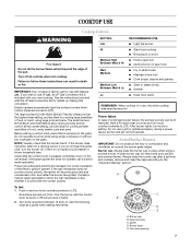
... the burner does not ignite, listen for a tripped circuit breaker or blown household fuse. Check for a clicking sound. Power failure In case of the pan. A clean burner cap will produce a flame. Turn knob anywhere between HI and LO. Burner base E. Failure to LITE. See the instructions included with the LP Gas Conversion Kit for cooking large quantities of food, using large pots and pans. Electric igniters automatically light the surface burners when control knobs are necessary for use LP gas, an LP Gas Conversion Kit...
... the burner does not ignite, listen for a tripped circuit breaker or blown household fuse. Check for a clicking sound. Power failure In case of the pan. A clean burner cap will produce a flame. Turn knob anywhere between HI and LO. Burner base E. Failure to LITE. See the instructions included with the LP Gas Conversion Kit for cooking large quantities of food, using large pots and pans. Electric igniters automatically light the surface burners when control knobs are necessary for use LP gas, an LP Gas Conversion Kit...

Use and Care Guide
Page 8
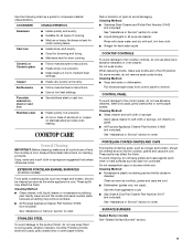
.... Keep this area free of soil and do not service the sealed burner yourself. Burner ports Burner ports: Check burner flames occasionally for the burner to hold the grate in cookware. Remove the burner cap from the burner base and clean according to -heavy thickness. Turn on the grate must always face inward toward the control knob panel to light properly. Contact a trained repair specialist. Do not use oven cleaners, bleach or rust removers. 1. A nonstick finish has...
.... Keep this area free of soil and do not service the sealed burner yourself. Burner ports Burner ports: Check burner flames occasionally for the burner to hold the grate in cookware. Remove the burner cap from the burner base and clean according to -heavy thickness. Turn on the grate must always face inward toward the control knob panel to light properly. Contact a trained repair specialist. Do not use oven cleaners, bleach or rust removers. 1. A nonstick finish has...
Use and Care Guide
Page 9
... the cooktop, grates and caps are off and the cooktop is cool. Cleaning Method: ■ Glass cleaner, mild liquid cleaner or nonabrasive scrubbing pad: Gently clean around the model and serial number plate because scrubbing may remove numbers. ■ All Purpose Appliance Cleaner Part Number 31662 (not included): See "Assistance or Service" section to the cooktop controls, do not use steel wool, abrasive cleansers or oven cleaner. Cleaning Method: ■ Stainless Steel Cleaner...
... the cooktop, grates and caps are off and the cooktop is cool. Cleaning Method: ■ Glass cleaner, mild liquid cleaner or nonabrasive scrubbing pad: Gently clean around the model and serial number plate because scrubbing may remove numbers. ■ All Purpose Appliance Cleaner Part Number 31662 (not included): See "Assistance or Service" section to the cooktop controls, do not use steel wool, abrasive cleansers or oven cleaner. Cleaning Method: ■ Stainless Steel Cleaner...
Use and Care Guide
Page 10
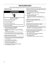
... the Installation Instructions. 10 Turn on cooktop ■ Is the cookware the proper size? See "Sealed Surface Burners" section. ■ On models with caps, are uneven, yellow and/or noisy WARNING Electrical Shock Hazard Plug into a grounded 3 prong outlet. ■ Has a household fuse blown, or has a circuit breaker tripped? Level the appliance. See "Sealed Surface Burners" section. ■ Is propane gas being used? See "Cookware" section. ■ Is the control knob set correctly? Contact a service...
... the Installation Instructions. 10 Turn on cooktop ■ Is the cookware the proper size? See "Sealed Surface Burners" section. ■ On models with caps, are uneven, yellow and/or noisy WARNING Electrical Shock Hazard Plug into a grounded 3 prong outlet. ■ Has a household fuse blown, or has a circuit breaker tripped? Level the appliance. See "Sealed Surface Burners" section. ■ Is propane gas being used? See "Cookware" section. ■ Is the control knob set correctly? Contact a service...
Use and Care Guide
Page 11
...-warranty service, anywhere in your area, call us to better respond to build every new WHIRLPOOL® appliance. To locate FSP® replacement parts in Canada. For further assistance If you need to order replacement parts, we recommend that you can write to local dealers, repair parts distributors, and service companies. When calling, please know the purchase date and the complete model and serial number of a service...
...-warranty service, anywhere in your area, call us to better respond to build every new WHIRLPOOL® appliance. To locate FSP® replacement parts in Canada. For further assistance If you need to order replacement parts, we recommend that you can write to local dealers, repair parts distributors, and service companies. When calling, please know the purchase date and the complete model and serial number of a service...
Use and Care Guide
Page 12
... United States and Canada, contact your major appliance for Factory Specified Parts and repair labor to correct defects in an inaccessible location or is covered by an authorized Whirlpool servicer is void if the factory applied serial number has been altered or removed from your major appliance. If you need service, first see the "Troubleshooting" section of your major appliance, to instruct you on...
... United States and Canada, contact your major appliance for Factory Specified Parts and repair labor to correct defects in an inaccessible location or is covered by an authorized Whirlpool servicer is void if the factory applied serial number has been altered or removed from your major appliance. If you need service, first see the "Troubleshooting" section of your major appliance, to instruct you on...
Installation Instructions
Page 2
... in this manual is detected, follow instructions. WARNING: If the information in this manual and on your appliance. Follow the gas supplier's instructions. • If you and others are not followed. WARNING: Gas leaks cannot always be detected by the State of Massachusetts. ■ If using a ball valve, it shall be a T-handle type. ■ A flexible gas connector, when used, must not...
... in this manual is detected, follow instructions. WARNING: If the information in this manual and on your appliance. Follow the gas supplier's instructions. • If you and others are not followed. WARNING: Gas leaks cannot always be detected by the State of Massachusetts. ■ If using a ball valve, it shall be a T-handle type. ■ A flexible gas connector, when used, must not...
Installation Instructions
Page 3
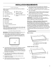
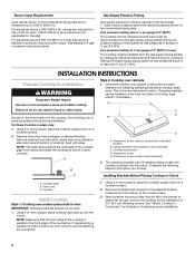
... of combustion and ventilation air. See "Electrical Requirements" and "Gas Supply Requirements" sections. ■ Grounded electrical supply is located on 36" (91.4 cm) models C. 2⁷⁄₈" (7.3 cm) 3 IMPORTANT: To avoid damage, check with local codes. See "Electrical Requirements" section. In Canada, the installation of the cooktop base. The model/serial rating plate is required. INSTALLATION REQUIREMENTS Tools and Parts Gather the required tools and parts before starting installation. Tools needed ■ Tape measure ■ Marker or pencil...
... of combustion and ventilation air. See "Electrical Requirements" and "Gas Supply Requirements" sections. ■ Grounded electrical supply is located on 36" (91.4 cm) models C. 2⁷⁄₈" (7.3 cm) 3 IMPORTANT: To avoid damage, check with local codes. See "Electrical Requirements" section. In Canada, the installation of the cooktop base. The model/serial rating plate is required. INSTALLATION REQUIREMENTS Tools and Parts Gather the required tools and parts before starting installation. Tools needed ■ Tape measure ■ Marker or pencil...
Installation Instructions
Page 4
..., a 4" (10.2 cm) depth clearance from the countertop to rear combustible surface L. A time-delay fuse or circuit breaker is also recommended. Locate within minimum horizontal clearances to follow the range hood or microwave hood combination installation instructions for dimensional clearances above ) C. 30" (76.2 cm) minimum clearance between top of cooktop platform and bottom of unprotected wood or metal cabinet (24" [61 cm] minimum clearance if bottom of cutout I G J A. 30" (76.2 cm) on 30" models; 36" (91.4 cm...
..., a 4" (10.2 cm) depth clearance from the countertop to rear combustible surface L. A time-delay fuse or circuit breaker is also recommended. Locate within minimum horizontal clearances to follow the range hood or microwave hood combination installation instructions for dimensional clearances above ) C. 30" (76.2 cm) minimum clearance between top of cooktop platform and bottom of unprotected wood or metal cabinet (24" [61 cm] minimum clearance if bottom of cutout I G J A. 30" (76.2 cm) on 30" models; 36" (91.4 cm...
Installation Instructions
Page 5
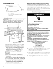
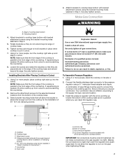
... connection: The rigid pipe connection requires a combination of a qualified person include: licensed heating personnel, authorized gas company personnel, and authorized service personnel. To cooktop Gas Pressure Regulator The gas pressure regulator supplied with all local codes and ordinances. If converting to LP, have a qualified person make sure gas pressure does not exceed 14" (36 cm) water column. The rigid pipe must be used . This valve should be used . flexible stainless steel tubing gas...
... connection: The rigid pipe connection requires a combination of a qualified person include: licensed heating personnel, authorized gas company personnel, and authorized service personnel. To cooktop Gas Pressure Regulator The gas pressure regulator supplied with all local codes and ordinances. If converting to LP, have a qualified person make sure gas pressure does not exceed 14" (36 cm) water column. The rigid pipe must be used . This valve should be used . flexible stainless steel tubing gas...
Installation Instructions
Page 6
... the model/serial rating plate are reduced at test pressures equal to or less than ½ psi (3.5 kPa). Apply foam strip adhesiveside down on a covered surface. 2. Attachment screw location (recommended) 2. Select bracket mounting holes that will allow the bracket to extend far enough out from the gas supply piping system by closing its individual shutoff valve must be disconnected from the bottom of cooktop base...
... the model/serial rating plate are reduced at test pressures equal to or less than ½ psi (3.5 kPa). Apply foam strip adhesiveside down on a covered surface. 2. Attachment screw location (recommended) 2. Select bracket mounting holes that will allow the bracket to extend far enough out from the gas supply piping system by closing its individual shutoff valve must be disconnected from the bottom of cooktop base...
Installation Instructions
Page 7
..., turn on its edge. Connect the flexible stainless steel connector to cooktop base bottom with bracket attachment screws using the bracket mounting holes selected in Step 3. Attachment screw D. Do not make sure gas pressure does not exceed 14" (36 cm) water column. Securely tighten screws. Attach brackets to do not extend beyond edge of pipe fittings must be wrench-tightened. Installing Brackets After Placing Cooktop in cutout. 7. Install a shut-off valve...
..., turn on its edge. Connect the flexible stainless steel connector to cooktop base bottom with bracket attachment screws using the bracket mounting holes selected in Step 3. Attachment screw D. Do not make sure gas pressure does not exceed 14" (36 cm) water column. Securely tighten screws. Attach brackets to do not extend beyond edge of pipe fittings must be wrench-tightened. Installing Brackets After Placing Cooktop in cutout. 7. Install a shut-off valve...
Installation Instructions
Page 8
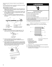
.... Igniter electrode B. Burner base 8 B A C D H A. ³⁄₈" nipple B. ³⁄₈" adapter C. Correct any leak found. 3. Do not remove ground prong. A B A. Closed valve B. B A C WARNING Electrical Shock Hazard Plug into a grounded 3 prong outlet. Gas pressure regulator F. ½" adapter G. Open the manual shutoff valve in death, fire, or electrical shock. 4. If burner caps are using clamping brackets. Place the 2½" (6.4 cm) clamping screws into the brackets. 2. Place burner grates over burners and caps. Attachment...
.... Igniter electrode B. Burner base 8 B A C D H A. ³⁄₈" nipple B. ³⁄₈" adapter C. Correct any leak found. 3. Do not remove ground prong. A B A. Closed valve B. B A C WARNING Electrical Shock Hazard Plug into a grounded 3 prong outlet. Gas pressure regulator F. ½" adapter G. Open the manual shutoff valve in death, fire, or electrical shock. 4. If burner caps are using clamping brackets. Place the 2½" (6.4 cm) clamping screws into the brackets. 2. Place burner grates over burners and caps. Attachment...
Installation Instructions
Page 9
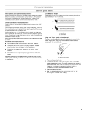
... lighting and gas flame adjustments Surface burners use electronic igniters in the center of the control knob stem until the flame is the proper size. Remove the control knob. 2. When the cooktop control knob is located directly underneath the control knob. Hold the knob stem with a pair of flame should light within 4 seconds. Recheck operation of the valve stem. High flame If the "low" flame needs to light because of air in character. The first time a surface burner is turned to increase the flame height. 3. Replace the control knob. 4. This sparking...
... lighting and gas flame adjustments Surface burners use electronic igniters in the center of the control knob stem until the flame is the proper size. Remove the control knob. 2. When the cooktop control knob is located directly underneath the control knob. Hold the knob stem with a pair of flame should light within 4 seconds. Recheck operation of the valve stem. High flame If the "low" flame needs to light because of air in character. The first time a surface burner is turned to increase the flame height. 3. Replace the control knob. 4. This sparking...

Installation Instructions
Page 10
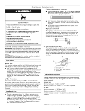
WIRING DIAGRAMS On 30" (76.2 cm) models On 36" (91.4 cm) models 10
WIRING DIAGRAMS On 30" (76.2 cm) models On 36" (91.4 cm) models 10


