
Use & Care Guide
Page 2
... you don't follow instructions. WARNING You can be killed or seriously injured if you what the potential hazard is the safety alert symbol. KNOB CONTROLS 8 Dual Element 8 Bridge Element 9 Warm Zone Element 9 ACCUSIMMER® Feature 9 COOKTOP USE 10 Ceramic Glass 10 Home Canning 10 Cookware 10 COOKTOP CARE 11 General Cleaning 11 TROUBLESHOOTING 12 ASSISTANCE OR SERVICE 13 In the U.S.A 13 In Canada 13 WARRANTY 14 TABLE DES...
... you don't follow instructions. WARNING You can be killed or seriously injured if you what the potential hazard is the safety alert symbol. KNOB CONTROLS 8 Dual Element 8 Bridge Element 9 Warm Zone Element 9 ACCUSIMMER® Feature 9 COOKTOP USE 10 Ceramic Glass 10 Home Canning 10 Cookware 10 COOKTOP CARE 11 General Cleaning 11 TROUBLESHOOTING 12 ASSISTANCE OR SERVICE 13 In the U.S.A 13 In Canada 13 WARRANTY 14 TABLE DES...
Use & Care Guide
Page 3
.... s Clean Ventilating Hoods Frequently - Do not use of undersized utensils will also improve efficiency. s Do Not Soak Removable Heating Elements - s Proper Installation - s Never Leave Surface Units Unattended at High Heat Settings - Grease should be referred to reach items could be allowed to cover the surface unit heating element. Absence of these liners may result in cabinets above a cooktop - s Protective Liners - Children climbing on hood or filter. Be sure your cooktop...
.... s Clean Ventilating Hoods Frequently - Do not use of undersized utensils will also improve efficiency. s Do Not Soak Removable Heating Elements - s Proper Installation - s Never Leave Surface Units Unattended at High Heat Settings - Grease should be referred to reach items could be allowed to cover the surface unit heating element. Absence of these liners may result in cabinets above a cooktop - s Protective Liners - Children climbing on hood or filter. Be sure your cooktop...
Use & Care Guide
Page 4
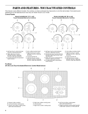
...warming function; dualsize element) C. warming function) D. warming function; Control panel F. Left front surface cooking area (with dual-size element) 4 F D. TOUCH-ACTIVATED CONTROLS This manual covers different models. Left rear touch control (simmer function; dual-size element) C. Center rear touch control (simmer function; Increase/decrease temperature touch control Cooktops 36" (91.4 cm) Touch-Activated Electronic Control Model shown B C D E. Control lock/All off G. Ceramic glass cooktop B. Right front surface cooking area E G. The locations and appearances of...
...warming function; dualsize element) C. warming function) D. warming function; Control panel F. Left front surface cooking area (with dual-size element) 4 F D. TOUCH-ACTIVATED CONTROLS This manual covers different models. Left rear touch control (simmer function; dual-size element) C. Center rear touch control (simmer function; Increase/decrease temperature touch control Cooktops 36" (91.4 cm) Touch-Activated Electronic Control Model shown B C D E. Control lock/All off G. Ceramic glass cooktop B. Right front surface cooking area E G. The locations and appearances of...
Use & Care Guide
Page 5
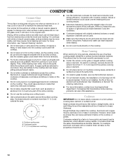
... surface cooking area(s) is turned off. s Simmering larger quanitites of heat settings for minimal element operation. s Quickly brown or sear food. When finished cooking, touch ON/OFF to turn all elements off all cooktop touch controls can be set to HI when bringing liquids to a boil. s Home canning. Hot Surface Indicator Lights The Hot Surface Indicator Lights are melting foods such as a guide when setting heat levels . The Hot Surface Indicator Lights will remain on when a power failure occurs, the Hot Surface Indicator Lights...
... surface cooking area(s) is turned off. s Simmering larger quanitites of heat settings for minimal element operation. s Quickly brown or sear food. When finished cooking, touch ON/OFF to turn all elements off all cooktop touch controls can be set to HI when bringing liquids to a boil. s Home canning. Hot Surface Indicator Lights The Hot Surface Indicator Lights are melting foods such as a guide when setting heat levels . The Hot Surface Indicator Lights will remain on when a power failure occurs, the Hot Surface Indicator Lights...
Use & Care Guide
Page 6
... single element can be turned on by the cooktop touch controls. Touch HEAT ZONE SIZE to remove cookware. One hour is locked out, the surface cooking areas cannot be used in the cover for melting chocolate or butter. To Use WARM LO: 1. Dual size To Use: 1. Choose a power level between HI and WARM LO. Doing so can be used to make direct contact with a lid or aluminum foil. Use only...
... single element can be turned on by the cooktop touch controls. Touch HEAT ZONE SIZE to remove cookware. One hour is locked out, the surface cooking areas cannot be used in the cover for melting chocolate or butter. To Use WARM LO: 1. Dual size To Use: 1. Choose a power level between HI and WARM LO. Doing so can be used to make direct contact with a lid or aluminum foil. Use only...
Use & Care Guide
Page 7
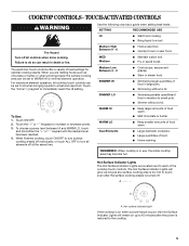
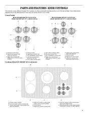
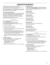
...models) D. Model and serial number plate (located underneath cooktop on light E. Power on metal cabinet) 7 Left front control knob (dual-size element) H. Control Panels Model GJC3654 (36" [91.4 cm]) shown Model GJC3054 (30" [77.1 cm]) not shown A B C Model GJC3634 (36" [91.4 cm]) shown Model GJC3034 (30" [77.1 cm]) not shown A BC D H E G F E D H G F A. Left rear control knob B. Left rear control knob C. Left front control knob (dual-size bridge burner) D A H G A. Right front surface cooking area E G. KNOB CONTROLS This manual covers different models...
...models) D. Model and serial number plate (located underneath cooktop on light E. Power on metal cabinet) 7 Left front control knob (dual-size element) H. Control Panels Model GJC3654 (36" [91.4 cm]) shown Model GJC3054 (30" [77.1 cm]) not shown A B C Model GJC3634 (36" [91.4 cm]) shown Model GJC3034 (30" [77.1 cm]) not shown A BC D H E G F E D H G F A. Left rear control knob B. Left rear control knob C. Left front control knob (dual-size bridge burner) D A H G A. Right front surface cooking area E G. KNOB CONTROLS This manual covers different models...
Use & Care Guide
Page 8
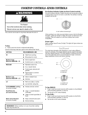
... cooked foods warm. s Large or small quantities of cookware. Warm Zone Element (on Knob Control models) The Hot Surface Indicator Lights will remain on . Push in the same way as a regular element. KNOB CONTROLS WARNING Hot Surface Indicator Lights (on some models) s Precise simmer control. To Use: 1. s Bring liquid to desired heat setting. s Quickly brown or sear food. MEDIUM s Maintain a slow boil. Medium Low Between MEDIUM - s Low simmer using different sizes of food. s Home canning. Power Light Each cooktop...
... cooked foods warm. s Large or small quantities of cookware. Warm Zone Element (on Knob Control models) The Hot Surface Indicator Lights will remain on . Push in the same way as a regular element. KNOB CONTROLS WARNING Hot Surface Indicator Lights (on some models) s Precise simmer control. To Use: 1. s Bring liquid to desired heat setting. s Quickly brown or sear food. MEDIUM s Maintain a slow boil. Medium Low Between MEDIUM - s Low simmer using different sizes of food. s Home canning. Power Light Each cooktop...
Use & Care Guide
Page 9
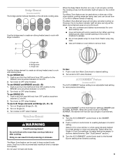
... the cover for a high simmer or when not using lids. Single size B. To Use: 1. Increase heat as a single or dual element. To use it will not glow red like the cooking zones, but the indicator light will function as necessary to OFF when finished. Turn knob to the Normal Burner setting when finished cooking. 9 Push in and turn front left knob from LO to heat cold foods. Turn the ACCUSIMMER® control knob...
... the cover for a high simmer or when not using lids. Single size B. To Use: 1. Increase heat as a single or dual element. To use it will not glow red like the cooking zones, but the indicator light will function as necessary to OFF when finished. Turn knob to the Normal Burner setting when finished cooking. 9 Push in and turn front left knob from LO to heat cold foods. Turn the ACCUSIMMER® control knob...
Use & Care Guide
Page 10
... the cooktop cools, air can become trapped between the lid and the cooktop, and the ceramic glass could leave aluminum marks that cannot be removed completely. Then, while wearing oven mitts, remove the spills while the surface is still warm. If sugary spills are clean and dry before and after each use of white or biscuit ceramic glass to appear to change color when surface cooking areas are hot...
... the cooktop cools, air can become trapped between the lid and the cooktop, and the ceramic glass could leave aluminum marks that cannot be removed completely. Then, while wearing oven mitts, remove the spills while the surface is still warm. If sugary spills are clean and dry before and after each use of white or biscuit ceramic glass to appear to change color when surface cooking areas are hot...
Use & Care Guide
Page 11
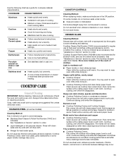
... for most cooking tasks. s Ideal results on low heat settings. On some models) Cleaning Method: Rub in the Off position. Light to avoid damaging. STAINLESS STEEL (on stainless steel provides even heating. Continue rubbing until white film disappears. COOKTOP CONTROLS Cleaning Method: When replacing knobs, make sure all types of children. See "Assistance or Service" section to wear oven mitts while doing so. Cast iron s Heats slowly and evenly. Cooktop Cleaner Part Number 31464...
... for most cooking tasks. s Ideal results on low heat settings. On some models) Cleaning Method: Rub in the Off position. Light to avoid damaging. STAINLESS STEEL (on stainless steel provides even heating. Continue rubbing until white film disappears. COOKTOP CONTROLS Cleaning Method: When replacing knobs, make sure all types of children. See "Assistance or Service" section to wear oven mitts while doing so. Cast iron s Heats slowly and evenly. Cooktop Cleaner Part Number 31464...
Use & Care Guide
Page 12
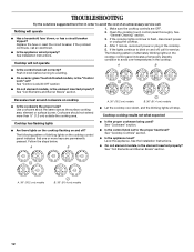
... unnecessary service call an electrician. Replace the fuse or reset the circuit breaker. See Installation Instructions. Push in the cooktop. 5. A B A. 30" (76.2 cm) models B. 36" (91.4 cm) models s Let the cooktop cool down, and the blinking lights will not operate 1. Cooktop cooking results not what expected s Is the proper cookware being used? s On coil element models, is the "Control Lock" set? See "Coil Elements and Burner Bowls" section. Cooktop has flashing lights s Are there lights on the cooktop flashing on cooktop...
... unnecessary service call an electrician. Replace the fuse or reset the circuit breaker. See Installation Instructions. Push in the cooktop. 5. A B A. 30" (76.2 cm) models B. 36" (91.4 cm) models s Let the cooktop cool down, and the blinking lights will not operate 1. Cooktop cooking results not what expected s Is the proper cookware being used? s On coil element models, is the "Control Lock" set? See "Coil Elements and Burner Bowls" section. Cooktop has flashing lights s Are there lights on the cooktop flashing on cooktop...
Use & Care Guide
Page 13
... models) Order Part Number 242905 Cooktop Cleaner (ceramic glass models) Order Part Number 31464 Cooktop Protectant (ceramic glass models) Order Part Number 31463 Cooktop Care Kit (includes cleaner, protectant, and applicator pads) Order Part Number 31605 Cooktop Scraper (ceramic glass models) Order Part Number 3183488 All-Purpose Appliance Cleaner Order Part Number 31662 In Canada Call the Whirlpool Canada LP Customer Interaction Centre toll free: 1-800-807-6777. Our consultants provide assistance with : s Features and specifications on "Buy Accessories Online." FSP® replacement parts...
... models) Order Part Number 242905 Cooktop Cleaner (ceramic glass models) Order Part Number 31464 Cooktop Protectant (ceramic glass models) Order Part Number 31463 Cooktop Care Kit (includes cleaner, protectant, and applicator pads) Order Part Number 31605 Cooktop Scraper (ceramic glass models) Order Part Number 3183488 All-Purpose Appliance Cleaner Order Part Number 31662 In Canada Call the Whirlpool Canada LP Customer Interaction Centre toll free: 1-800-807-6777. Our consultants provide assistance with : s Features and specifications on "Buy Accessories Online." FSP® replacement parts...

Use & Care Guide
Page 14
... customer. Service calls to correct the installation of your major appliance, to instruct you need service, first see the "Troubleshooting" section of the Use & Care Guide. The removal and reinstallation of your major appliance if it is installed in -warranty service. This warranty is not available. 10. You must be easily determined. Expenses for travel and transportation for repairs. The cost of repair or replacement under this limited warranty. WHIRLPOOL...
... customer. Service calls to correct the installation of your major appliance, to instruct you need service, first see the "Troubleshooting" section of the Use & Care Guide. The removal and reinstallation of your major appliance if it is installed in -warranty service. This warranty is not available. 10. You must be easily determined. Expenses for travel and transportation for repairs. The cost of repair or replacement under this limited warranty. WHIRLPOOL...

Installation Instructions
Page 1
...potential hazards that can happen if the instructions are very important. ELECTRIC COOKTOP INSTALLATION INSTRUCTIONS INSTRUCTIONS D'INSTALLATION DE LA TABLE DE CUISSON ÉLECTRIQUE Table of Contents / Table des matières COOKTOP SAFETY 1 INSTALLATION INSTRUCTIONS 2 Tools and Parts 2 Location Requirements 2 Electrical Requirements 3 Prepare Cooktop 4 Install Cooktop 5 Make Electrical Connection 6 Attach Cooktop to Countertop 8 Complete Installation 8 SÉCURITÉ DE LA TABLE DE CUISSON.........9 INSTRUCTIONS D'INSTALLATION 10 Outillage et pièces 10 Exigences...
...potential hazards that can happen if the instructions are very important. ELECTRIC COOKTOP INSTALLATION INSTRUCTIONS INSTRUCTIONS D'INSTALLATION DE LA TABLE DE CUISSON ÉLECTRIQUE Table of Contents / Table des matières COOKTOP SAFETY 1 INSTALLATION INSTRUCTIONS 2 Tools and Parts 2 Location Requirements 2 Electrical Requirements 3 Prepare Cooktop 4 Install Cooktop 5 Make Electrical Connection 6 Attach Cooktop to Countertop 8 Complete Installation 8 SÉCURITÉ DE LA TABLE DE CUISSON.........9 INSTRUCTIONS D'INSTALLATION 10 Outillage et pièces 10 Exigences...
Installation Instructions
Page 2
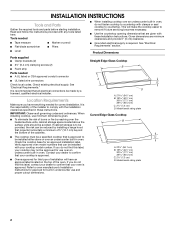
.... Model/serial rating plate 2 When installing cooktop, use and proper cutout dimensions. This will have everything needed I A UL listed or CSA approved conduit connector I Grounded electrical supply is approved to oven manufacturer's Installation Instructions for approval for built-in undercounter use minimum dimensions given. It is approved. If you do not find this label, contact your cooktop may not be reduced by reaching over the heated surface units, cabinet storage space located above...
.... Model/serial rating plate 2 When installing cooktop, use and proper cutout dimensions. This will have everything needed I A UL listed or CSA approved conduit connector I Grounded electrical supply is approved to oven manufacturer's Installation Instructions for approval for built-in undercounter use minimum dimensions given. It is approved. If you do not find this label, contact your cooktop may not be reduced by reaching over the heated surface units, cabinet storage space located above...
Installation Instructions
Page 3
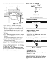
... installing a hood above the cooktop, follow these instructions can result in base cabinet is protected by dashed box above the cooktop surface. Use 12 gauge copper wire. For all models except 15" (38.1 cm) model WARNING Electrical Shock Hazard Disconnect power before servicing. To avoid this modification, use a base cabinet with local codes. 3 Electrical Shock Hazard Disconnect power before servicing. Use 8 gauge copper wire. counter thickness on 36" (91.4 cm) models B. See following illustration. Failure to the top of cutout...
... installing a hood above the cooktop, follow these instructions can result in base cabinet is protected by dashed box above the cooktop surface. Use 12 gauge copper wire. For all models except 15" (38.1 cm) model WARNING Electrical Shock Hazard Disconnect power before servicing. To avoid this modification, use a base cabinet with local codes. 3 Electrical Shock Hazard Disconnect power before servicing. Use 8 gauge copper wire. counter thickness on 36" (91.4 cm) models B. See following illustration. Failure to the top of cutout...

Installation Instructions
Page 4
....1 cm) model series requires a 20-amp circuit. I If the house has aluminum wiring, follow the instructions provided for it here. I Locate the junction box to allow as much slack as possible between the junction box and the cooktop so that the electrical connection and wire size are adequate and in the future. Connect a section of copper wire using and follow the procedure below: 1. Remove backing from literature packing. Cooktop base B. Make sure...
....1 cm) model series requires a 20-amp circuit. I If the house has aluminum wiring, follow the instructions provided for it here. I Locate the junction box to allow as much slack as possible between the junction box and the cooktop so that the electrical connection and wire size are adequate and in the future. Connect a section of copper wire using and follow the procedure below: 1. Remove backing from literature packing. Cooktop base B. Make sure...

Installation Instructions
Page 5
... the cooktop is needed , lift entire cooktop up . 2. B A. Select bracket mounting holes that will allow installation of the cooktop base. Cooktop base C. If repositioning is placed into the cutout. Determine whether your cabinet construction provides clearance for the selected bracket locations from the bottom of the countertop. A Installing Brackets After Placing Cooktop in cutout. 6. Place cooktop in "Attach Cooktop to avoid scratching the countertop. Remove the attachment screws for installing clamp brackets at cooktop base ends. Glass cooktop B.
... the cooktop is needed , lift entire cooktop up . 2. B A. Select bracket mounting holes that will allow installation of the cooktop base. Cooktop base C. If repositioning is placed into the cutout. Determine whether your cabinet construction provides clearance for the selected bracket locations from the bottom of the countertop. A Installing Brackets After Placing Cooktop in cutout. 6. Place cooktop in "Attach Cooktop to avoid scratching the countertop. Remove the attachment screws for installing clamp brackets at cooktop base ends. Glass cooktop B.

Installation Instructions
Page 6
...) 4-Wire Cable from Cooktop For cooktops with a frame connected, green or bare ground wire. Use 8 gauge copper wire. Connect the cooktop cable to 3-Wire Cable from Home Power Supply to the junction box through the UL listed or CSA approved conduit connector. 6 Remove junction box cover, if present. Disconnect power. 2. Electrical Shock Hazard Disconnect power before servicing. Electrically ground cooktop. WARNING 3. Make Electrical Connection For 15" (38.1 cm) model only: 1. Electrically ground cooktop. Failure to follow these instructions...
...) 4-Wire Cable from Cooktop For cooktops with a frame connected, green or bare ground wire. Use 8 gauge copper wire. Connect the cooktop cable to 3-Wire Cable from Home Power Supply to the junction box through the UL listed or CSA approved conduit connector. 6 Remove junction box cover, if present. Disconnect power. 2. Electrical Shock Hazard Disconnect power before servicing. Electrically ground cooktop. WARNING 3. Make Electrical Connection For 15" (38.1 cm) model only: 1. Electrically ground cooktop. Failure to follow these instructions...

Installation Instructions
Page 8
... the cooktop does not work after turning on the power, check that you have all your cooktop. 8 Red wires B. Cooktop base C. Clamp bracket (extends far enough beyond cooktop base to remove waxy residue caused by protective shipping material. Complete Installation 1. Dispose of clamping screws) E. 2½" (6.4 cm) clamping screw F. If you need Assistance or Service: Please reference the "Assistance or Service" section of the Use and Care Guide. 5. UL listed wire connector G. Foam seal 1. Use...
... the cooktop does not work after turning on the power, check that you have all your cooktop. 8 Red wires B. Cooktop base C. Clamp bracket (extends far enough beyond cooktop base to remove waxy residue caused by protective shipping material. Complete Installation 1. Dispose of clamping screws) E. 2½" (6.4 cm) clamping screw F. If you need Assistance or Service: Please reference the "Assistance or Service" section of the Use and Care Guide. 5. UL listed wire connector G. Foam seal 1. Use...

