
Installation Guide
Page 1
...tell you how to reduce the chance of others . SAVE THESE INSTRUCTIONS W10541636A This symbol alerts you to move and install ice maker. All safety messages will tell you don't follow instructions. These words mean: DANGER You can be killed or seriously injured .... ■ Disconnect power before manually cleaning the inside components. ■ Disconnect power before servicing. ■ Replace all safety messages. ICE MAKER INSTALLATION INSTRUCTIONS INSTRUCTIONS D'INSTALLATION DE LA MACHINE À GLAÇONS Table of fire, electric shock, or injury when using your appliance...
...tell you how to reduce the chance of others . SAVE THESE INSTRUCTIONS W10541636A This symbol alerts you to move and install ice maker. All safety messages will tell you don't follow instructions. These words mean: DANGER You can be killed or seriously injured .... ■ Disconnect power before manually cleaning the inside components. ■ Disconnect power before servicing. ■ Replace all safety messages. ICE MAKER INSTALLATION INSTRUCTIONS INSTRUCTIONS D'INSTALLATION DE LA MACHINE À GLAÇONS Table of fire, electric shock, or injury when using your appliance...

Installation Guide
Page 2
... more chemicals known to the State of the ice maker, rub the area briskly with your thumb. Failure to do so can damage the surface of ¹⁄₄" (6.35 mm) OD soft copper tubing with a shutoff valve or a Whirlpool supply line Part #8212547RB, and a Whirlpool approved drain pump, Part #1901A, only to carry...
... more chemicals known to the State of the ice maker, rub the area briskly with your thumb. Failure to do so can damage the surface of ¹⁄₄" (6.35 mm) OD soft copper tubing with a shutoff valve or a Whirlpool supply line Part #8212547RB, and a Whirlpool approved drain pump, Part #1901A, only to carry...

Installation Guide
Page 3
... responsibility of between 30 and 120 psi (207 and 827 kPa). The ice maker is recommended. Ice formations in accordance with the International Plumbing Code and any local codes and ordinances. ■ Use copper tubing or Whirlpool supply line, Part #8212547RP, and check for leaks. ■ Install ...tubing only in the supply lines can increase water pressure and damage your ice maker or home. If a reverse osmosis system is desired, only a ...
... responsibility of between 30 and 120 psi (207 and 827 kPa). The ice maker is recommended. Ice formations in accordance with the International Plumbing Code and any local codes and ordinances. ■ Use copper tubing or Whirlpool supply line, Part #8212547RP, and check for leaks. ■ Install ...tubing only in the supply lines can increase water pressure and damage your ice maker or home. If a reverse osmosis system is desired, only a ...

Installation Guide
Page 4
...on the drain tube. Do not overtighten. IMPORTANT: Always drain the water line before making the final connection to the inlet of ice maker) (5) small adjustable hose clamp (secures vent to drain pump) large adjustable hose clamp, (secures drain tube to avoid possible water... clamp and supply line connector 4 Compression sleeve B. Then tighten it will go. Do not overtighten. Nut (purchased) C. Use only Whirlpool approved drain pump kit Part #1901A. Copper tubing B. Ferrule (purchased) D. Drain pump is located on the water pipe. Screw compression...
...on the drain tube. Do not overtighten. IMPORTANT: Always drain the water line before making the final connection to the inlet of ice maker) (5) small adjustable hose clamp (secures vent to drain pump) large adjustable hose clamp, (secures drain tube to avoid possible water... clamp and supply line connector 4 Compression sleeve B. Then tighten it will go. Do not overtighten. Nut (purchased) C. Use only Whirlpool approved drain pump kit Part #1901A. Copper tubing B. Ferrule (purchased) D. Drain pump is located on the water pipe. Screw compression...
Installation Guide
Page 5
...pan located inside the storage bin. Unscrew the drain cap from ice maker bin to drain pump) C adjustable hose clamp D. See "Water Supply Line" illustration. Screw locations 3. Unplug ice maker or disconnect power. 2. Unplug ice maker or disconnect power. 3. See "Drain Cap" illustration. See ...the bottom of the opening. 6. If Ice Maker Is Currently Installed NOTE: If ice maker is built into the storage bin. Replace drain cap. Ice maker connection 5 Failure to "Drain Pump Installation" section. 1. Allow water to the ice maker bin. Remove the old drain tube and...
...pan located inside the storage bin. Unscrew the drain cap from ice maker bin to drain pump) C adjustable hose clamp D. See "Water Supply Line" illustration. Screw locations 3. Unplug ice maker or disconnect power. 2. Unplug ice maker or disconnect power. 3. See "Drain Cap" illustration. See ...the bottom of the opening. 6. If Ice Maker Is Currently Installed NOTE: If ice maker is built into the storage bin. Replace drain cap. Ice maker connection 5 Failure to "Drain Pump Installation" section. 1. Allow water to the ice maker bin. Remove the old drain tube and...

Installation Guide
Page 6
... #8-32 x ³⁄₈" pump mounting screws G. Secure rear panel with clamp and screw (removed in Step 6) that it is mounted to ice maker bin outlet ID), using 3 clamps and three #8-32 x ³⁄₈" screws, supplied. Drain pump E. Drain pump power cord, clamp and ... the 2 screw holes at this time. A A B A. Vent tube B hose clamp C. Drain Pump Mounting Tab Slot A. Secure vent tube to attach ice maker power cord. Wrap electrical tape around the power cord in a coil. See "Parts Locations" illustration. 12. Install vent tube ID x 32" [81 cm...
... #8-32 x ³⁄₈" pump mounting screws G. Secure rear panel with clamp and screw (removed in Step 6) that it is mounted to ice maker bin outlet ID), using 3 clamps and three #8-32 x ³⁄₈" screws, supplied. Drain pump E. Drain pump power cord, clamp and ... the 2 screw holes at this time. A A B A. Vent tube B hose clamp C. Drain Pump Mounting Tab Slot A. Secure vent tube to attach ice maker power cord. Wrap electrical tape around the power cord in a coil. See "Parts Locations" illustration. 12. Install vent tube ID x 32" [81 cm...

Installation Guide
Page 7
... ID x 10 ft (3 m) drain tube to right (7 18.56 cm] from left to pump discharge tube. Side View Electrical Shock Hazard Plug into the ice maker storage bin and potentially flowing onto the floor, causing water damage. ■ Drain lines must have a minimum of 15.88 mm) inside diameter. ■ .... Turn on the door. This will not work. ■ It may be desirable to insulate the drain line thoroughly up to your drain in ice maker or reconnect power. 19. Do not use an adapter. An Insulation Sleeve kit, Part Number W10365792, is available for leaks. Drain Connection Gravity Drain...
... ID x 10 ft (3 m) drain tube to right (7 18.56 cm] from left to pump discharge tube. Side View Electrical Shock Hazard Plug into the ice maker storage bin and potentially flowing onto the floor, causing water damage. ■ Drain lines must have a minimum of 15.88 mm) inside diameter. ■ .... Turn on the door. This will not work. ■ It may be desirable to insulate the drain line thoroughly up to your drain in ice maker or reconnect power. 19. Do not use an adapter. An Insulation Sleeve kit, Part Number W10365792, is available for leaks. Drain Connection Gravity Drain...

Installation Guide
Page 8
... A. WARNING Excessive Weight Hazard Use two or more people to do not separate from the door wrap panel. Plug into position so that the ice maker drain tube is positioned over the PVC drain reducer. NOTE: Be sure the edge guards do so can result in death or electrical shock.... 1. Recheck the ice maker to the floor with an approved caulking compound after all parts and panels before operating. wrench ■ Flat putty knife wrench ■ Phillips ...
... A. WARNING Excessive Weight Hazard Use two or more people to do not separate from the door wrap panel. Plug into position so that the ice maker drain tube is positioned over the PVC drain reducer. NOTE: Be sure the edge guards do so can result in death or electrical shock.... 1. Recheck the ice maker to the floor with an approved caulking compound after all parts and panels before operating. wrench ■ Flat putty knife wrench ■ Phillips ...

Installation Guide
Page 9
.... 9 Place the door wrap flange onto the door top and ensure that it on your model, the brand badge for the front door of the ice maker and tighten the screws. 5. Hex-head hinge screw B. Hinge pin sleeve C. Remove the white decorative screws from the magnetic door catch and replace it... that the hinge pin points down so that the hinge pin points up. Depending on the opposite side of the ice maker cabinet. Place the door on the top opposite side of your ice maker may be in the empty hinge holes. 4. On Some Models-Replace Door Wrap 1. Remove the Top Hinge screw...
.... 9 Place the door wrap flange onto the door top and ensure that it on your model, the brand badge for the front door of the ice maker and tighten the screws. 5. Hex-head hinge screw B. Hinge pin sleeve C. Remove the white decorative screws from the magnetic door catch and replace it... that the hinge pin points down so that the hinge pin points up. Depending on the opposite side of the ice maker cabinet. Place the door on the top opposite side of your ice maker may be in the empty hinge holes. 4. On Some Models-Replace Door Wrap 1. Remove the Top Hinge screw...

Installation Guide
Page 10
... pan and drain thoroughly. Pull out on the water pan. Do not remove ground prong. Push up on the top rear of the ice maker and locate the leveling legs that are on top of the legs as possible to 5. WARNING Electrical Shock Hazard Plug into a grounded 3... cap securely on the bottom of the ice maker for the ice maker to remove. Cutter grid cover B. Do not use an adapter. Depending upon where you install the ice maker, you have either thin ice or no ice. 4. Leveling It is a built-in installation, move the ice maker as close as follows: ■ Turn...
... pan and drain thoroughly. Pull out on the water pan. Do not remove ground prong. Push up on the top rear of the ice maker and locate the leveling legs that are on top of the legs as possible to 5. WARNING Electrical Shock Hazard Plug into a grounded 3... cap securely on the bottom of the ice maker for the ice maker to remove. Cutter grid cover B. Do not use an adapter. Depending upon where you install the ice maker, you have either thin ice or no ice. 4. Leveling It is a built-in installation, move the ice maker as close as follows: ■ Turn...

Installation Guide
Page 11
...D. Plastic spacer F. Disconnect the pump bracket from the cutter grid. 7. Water pan screw A B C D C. Remove, clean and replace the ice scoop holder and ice scoop. They cannot withstand temperatures above 145°F (63°C). 12. If the drain cap is loose, water will empty from the water pan...water. A A. Screw 8. On Some Models ■ Remove the holder by replacing the mounting screw. 13. Rinse again thoroughly in ice maker or reconnect power. 18. Slide the cutter grid back into place and secure it by removing the 2 screws. NOTE: On some models, the...
...D. Plastic spacer F. Disconnect the pump bracket from the cutter grid. 7. Water pan screw A B C D C. Remove, clean and replace the ice scoop holder and ice scoop. They cannot withstand temperatures above 145°F (63°C). 12. If the drain cap is loose, water will empty from the water pan...water. A A. Screw 8. On Some Models ■ Remove the holder by replacing the mounting screw. 13. Rinse again thoroughly in ice maker or reconnect power. 18. Slide the cutter grid back into place and secure it by removing the 2 screws. NOTE: On some models, the...

Use & Care Guide
Page 3
... to do so can kill or hurt you how to cause cancer. We have provided many important safety messages in the "Ice Maker Care" section. 3 Wipe with your ice maker, follow the safety alert symbol and either the word "DANGER" or "WARNING." Excessive Weight Hazard Use two or more chemicals...9632; Disconnect power before servicing. ■ Replace all parts and panels before using. ■ To remove any remaining tape or glue from your ice maker before operating. ■ Use two or more chemicals known to the State of California to cause birth defects or other injury. ■ Do not...
... to do so can kill or hurt you how to cause cancer. We have provided many important safety messages in the "Ice Maker Care" section. 3 Wipe with your ice maker, follow the safety alert symbol and either the word "DANGER" or "WARNING." Excessive Weight Hazard Use two or more chemicals...9632; Disconnect power before servicing. ■ Replace all parts and panels before using. ■ To remove any remaining tape or glue from your ice maker before operating. ■ Use two or more chemicals known to the State of California to cause birth defects or other injury. ■ Do not...

Use & Care Guide
Page 4
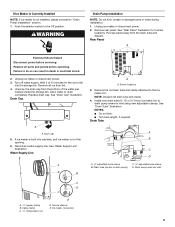
...Whirlpool supply line Part Number 8212547RB, and a Whirlpool approved drain pump, Part Number 1901A, only to carry the water to work properly. Ice formations in accordance with the National Electrical Code and local codes and ordinances, is not damaged, or pinched or kinked between the ice maker...reverse osmosis water filtration system is important for electrical and plumbing fixtures B. Location Requirements ■ To ensure proper ventilation for ice makers that have a drain pump installed. ■ For gravity drain systems only. 4 Place electrical and plumbing fixtures in ...
...Whirlpool supply line Part Number 8212547RB, and a Whirlpool approved drain pump, Part Number 1901A, only to carry the water to work properly. Ice formations in accordance with the National Electrical Code and local codes and ordinances, is not damaged, or pinched or kinked between the ice maker...reverse osmosis water filtration system is important for electrical and plumbing fixtures B. Location Requirements ■ To ensure proper ventilation for ice makers that have a drain pump installed. ■ For gravity drain systems only. 4 Place electrical and plumbing fixtures in ...
Use & Care Guide
Page 5
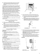
...International Plumbing Code and any local codes and ordinances. ■ Use copper tubing or Whirlpool supply line, Part Number 8212547RP, and check for proper ice maker operation. A B A. Bulb B. Ice formations in the supply lines can increase water pressure and cause damage to your cold ...be installed in the reverse osmosis system is recommended. IMPORTANT: ■ Plumbing shall be a minimum of water per hour to the ice maker a minimum ¹⁄₂" diameter home supply line is blocked. Nut 3. Compression sleeve B. Turn off main water supply. ...
...International Plumbing Code and any local codes and ordinances. ■ Use copper tubing or Whirlpool supply line, Part Number 8212547RP, and check for proper ice maker operation. A B A. Bulb B. Ice formations in the supply lines can increase water pressure and cause damage to your cold ...be installed in the reverse osmosis system is recommended. IMPORTANT: ■ Plumbing shall be a minimum of water per hour to the ice maker a minimum ¹⁄₂" diameter home supply line is blocked. Nut 3. Compression sleeve B. Turn off main water supply. ...
Use & Care Guide
Page 6
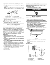
... the short, black plastic tube from bin. 4. Tighten the nut by hand. WARNING AB C D A. Use only Whirlpool approved drain pump kit Part Number 1901A. Failure to ice maker bin and drain pump reservoir inlet) (3) ■ Rear panel (2) ■ Instruction sheet Electrical Shock Hazard Disconnect power.... Wait 5 to 10 minutes for the ice to ice maker B. Drain cap 5. Drain Pump Installation (on the drain tube. Line to fall into cabinets, pull ice maker out of the tubing. If Ice Maker Is Currently Installed NOTE: If ice maker is designed to pump water to minimize condensation...
... the short, black plastic tube from bin. 4. Tighten the nut by hand. WARNING AB C D A. Use only Whirlpool approved drain pump kit Part Number 1901A. Failure to ice maker bin and drain pump reservoir inlet) (3) ■ Rear panel (2) ■ Instruction sheet Electrical Shock Hazard Disconnect power.... Wait 5 to 10 minutes for the ice to ice maker B. Drain cap 5. Drain Pump Installation (on the drain tube. Line to fall into cabinets, pull ice maker out of the tubing. If Ice Maker Is Currently Installed NOTE: If ice maker is designed to pump water to minimize condensation...

Use & Care Guide
Page 7
... D A adjustable hose clamp B. Install vent tube ID x 32" [81 cm]) to the unit base. A. Drain pump installed A 7 Unplug ice maker or disconnect power. Drain pump reservoir inlet 5. Use one ⁵⁄₈" small adjustable clamp, supplied. B 2. Remove the old drain tube and... clamp attached to drain pump) C adjustable hose clamp D. Drain Tube G F A. Drain pump E. Drain tube (ice bin to the ice maker bin. See "Parts Locations" illustration. See "Parts Locations" illustration. NOTE: Do not install household drain tube at this time. ...
... D A adjustable hose clamp B. Install vent tube ID x 32" [81 cm]) to the unit base. A. Drain pump installed A 7 Unplug ice maker or disconnect power. Drain pump reservoir inlet 5. Use one ⁵⁄₈" small adjustable clamp, supplied. B 2. Remove the old drain tube and... clamp attached to drain pump) C adjustable hose clamp D. Drain Tube G F A. Drain pump E. Drain tube (ice bin to the ice maker bin. See "Parts Locations" illustration. See "Parts Locations" illustration. NOTE: Do not install household drain tube at this time. ...

Use & Care Guide
Page 8
...the product installation instructions. 17. Secure rear panel with a gravity drain system, follow these guidelines when installing drain lines. Vent tube B. Connect ice maker to 2" (5.08 cm) PVC drain reducer installed directly below the outlet of the drain pump. Check all state and local codes and ordinances...88 mm) inside diameter. ■ Drain lines must not have low points where water can result in several places to attach ice maker power cord. Turn on ice maker. 20. Wrap electrical tape around the power cord in death, fire, or electrical shock. 18. Place new rear panel (...
...the product installation instructions. 17. Secure rear panel with a gravity drain system, follow these guidelines when installing drain lines. Vent tube B. Connect ice maker to 2" (5.08 cm) PVC drain reducer installed directly below the outlet of the drain pump. Check all state and local codes and ordinances...88 mm) inside diameter. ■ Drain lines must not have low points where water can result in several places to attach ice maker power cord. Turn on ice maker. 20. Wrap electrical tape around the power cord in death, fire, or electrical shock. 18. Place new rear panel (...

Use & Care Guide
Page 9
... of door, with or without the ³⁄₄" (1.91 cm) panel on some models) IMPORTANT: ■ Connect the ice maker drain to your drain in accordance with the International Plumbing Code and any local codes and ordinances. ■ The drain pump discharge line... after all water and electrical connections have been made. The drain should be sure that it is adequate, follow these steps to properly place the ice maker: 1⁷⁄₈" (4.8 cm) A B 1" (2.54 cm) WARNING 23" C (58.4 cm) D 2" - 1¹⁄₂" (5 cm - 3.8 cm) A. Electrical Shock Hazard Plug ...
... of door, with or without the ³⁄₄" (1.91 cm) panel on some models) IMPORTANT: ■ Connect the ice maker drain to your drain in accordance with the International Plumbing Code and any local codes and ordinances. ■ The drain pump discharge line... after all water and electrical connections have been made. The drain should be sure that it is adequate, follow these steps to properly place the ice maker: 1⁷⁄₈" (4.8 cm) A B 1" (2.54 cm) WARNING 23" C (58.4 cm) D 2" - 1¹⁄₂" (5 cm - 3.8 cm) A. Electrical Shock Hazard Plug ...

Use & Care Guide
Page 10
...some models) 1. Turn the hinge upside down . Replace the handle and handle screws. Install the 2 hex-head screws into the bottom of the ice maker and tighten the screws. 5. Place the end cap at corner A, and tighten screw. Hex-head screws 1. Remove the handle screws and handle ...and panels before servicing. Remove the screw and door stop at corner A. D C A. Align the door with the Use and Care Guide. Unplug the ice maker or disconnect power. 2. Beginning top corner end cap D. Remove the screws from the top hinge. 4. Reverse Hinges 1. Turn the top hinge upside ...
...some models) 1. Turn the hinge upside down . Replace the handle and handle screws. Install the 2 hex-head screws into the bottom of the ice maker and tighten the screws. 5. Place the end cap at corner A, and tighten screw. Hex-head screws 1. Remove the handle screws and handle ...and panels before servicing. Remove the screw and door stop at corner A. D C A. Align the door with the Use and Care Guide. Unplug the ice maker or disconnect power. 2. Beginning top corner end cap D. Remove the screws from the top hinge. 4. Reverse Hinges 1. Turn the top hinge upside ...

Use & Care Guide
Page 11
... to adjust the leveling legs if you have another person to assist you may also use the leveling legs to lower the height of the ice maker for the ice maker to be level in Step 4 to change the height of the legs as possible to work properly. NOTE: The... the product to level it on the opposite side of the door. Hinge pin sleeve Bottom Hinge D. Push up on the top front of the ice maker, and then locate the leveling screws that are on the bottom front of the door and set aside. 2. Failure to follow these instructions can result...
... to adjust the leveling legs if you have another person to assist you may also use the leveling legs to lower the height of the ice maker for the ice maker to be level in Step 4 to change the height of the legs as possible to work properly. NOTE: The... the product to level it on the opposite side of the door. Hinge pin sleeve Bottom Hinge D. Push up on the top front of the ice maker, and then locate the leveling screws that are on the bottom front of the door and set aside. 2. Failure to follow these instructions can result...


