
Installation Guide
Page 1
... Maker 2 Location Requirements 2 Electrical Requirements 3 Water Supply Requirements 3 Vacation or Extended Time Without Use 3 Connect Water Supply 3 Ice Maker Drain Pump Installation 4 Drain Connection 7 Ice Maker Door Reversal-Side Swing Only 8 Leveling 10 Cleaning 10 INSTRUCTIONS D'INSTALLATION 13 Déballage de la machine à ...224; la canalisation d'eau 14 Installation de la pompe de vidange de la machine à glaçons 15 Raccordement au drain de vidange 18 Inversion du sens d'installation de la machine à glaçons- All safety messages will tell you what...
... Maker 2 Location Requirements 2 Electrical Requirements 3 Water Supply Requirements 3 Vacation or Extended Time Without Use 3 Connect Water Supply 3 Ice Maker Drain Pump Installation 4 Drain Connection 7 Ice Maker Door Reversal-Side Swing Only 8 Leveling 10 Cleaning 10 INSTRUCTIONS D'INSTALLATION 13 Déballage de la machine à ...224; la canalisation d'eau 14 Installation de la pompe de vidange de la machine à glaçons 15 Raccordement au drain de vidange 18 Inversion du sens d'installation de la machine à glaçons- All safety messages will tell you what...

Installation Guide
Page 2
...; Check that the water supply line is not damaged, or pinched or kinked between the ice maker and the cabinet. ■ Check that the drain line (on some models) is not damaged, or pinched or kinked between 70°F and 90°F (21ºC and 32°C). &#...: This product contains one or more chemicals known to the State of California to an existing drain. ■ Choose a well ventilated area with a shutoff valve or a Whirlpool supply line Part #8212547RB, and a Whirlpool approved drain pump, Part #1901A, only to carry the water to cause birth defects or other injury. INSTALLATION...
...; Check that the water supply line is not damaged, or pinched or kinked between the ice maker and the cabinet. ■ Check that the drain line (on some models) is not damaged, or pinched or kinked between 70°F and 90°F (21ºC and 32°C). &#...: This product contains one or more chemicals known to the State of California to an existing drain. ■ Choose a well ventilated area with a shutoff valve or a Whirlpool supply line Part #8212547RB, and a Whirlpool approved drain pump, Part #1901A, only to carry the water to cause birth defects or other injury. INSTALLATION...

Installation Guide
Page 3
... in accordance with the International Plumbing Code and any local codes and ordinances. ■ Use copper tubing or Whirlpool supply line, Part #8212547RP, and check for ice makers that have a drain pump installed. ■ For gravity drain systems only. ■ The pressure of the water supply coming out of a reverse osmosis system going to...
... in accordance with the International Plumbing Code and any local codes and ordinances. ■ Use copper tubing or Whirlpool supply line, Part #8212547RP, and check for ice makers that have a drain pump installed. ■ For gravity drain systems only. ■ The pressure of the water supply coming out of a reverse osmosis system going to...

Installation Guide
Page 4
...ON. 10. Kit Contains: ■ Drain pump kit Part #1901A ID x 5¹⁄₈" drain tube (ice maker bin to drain pump reservoir inlet) ID x 10 ft (3 m) drain tube hose (drain pump discharge to household drain) ID x 32" (81 cm) vent tube (drain pump reservoir vent to ice maker cabinet back)... local codes and ordinances. Bulb B. Do not overtighten. Drain pump is available for leaks. Insulated tube kit Part #W10365792 is designed to pump water to connect the copper tubing. Use only Whirlpool approved drain pump kit Part #1901A. 6. Now you have the proper ...
...ON. 10. Kit Contains: ■ Drain pump kit Part #1901A ID x 5¹⁄₈" drain tube (ice maker bin to drain pump reservoir inlet) ID x 10 ft (3 m) drain tube hose (drain pump discharge to household drain) ID x 32" (81 cm) vent tube (drain pump reservoir vent to ice maker cabinet back)... local codes and ordinances. Bulb B. Do not overtighten. Drain pump is available for leaks. Insulated tube kit Part #W10365792 is designed to pump water to connect the copper tubing. Use only Whirlpool approved drain pump kit Part #1901A. 6. Now you have the proper ...
Installation Guide
Page 5
... do so can result in death or electrical shock. 2. Pull rear panel away from the bottom of the opening. 6. Drain Cap A A. Water Supply Line A B B A A. Cable clamp C. ¹⁄₄" compression nut C D C E D. Drain cap 5. Drain pump reservoir inlet A. ¹⁄₄" copper tubing B. Unplug ice maker or disconnect power. 2. Wait 5 to 10 minutes for 5 screw...
... do so can result in death or electrical shock. 2. Pull rear panel away from the bottom of the opening. 6. Drain Cap A A. Water Supply Line A B B A A. Cable clamp C. ¹⁄₄" compression nut C D C E D. Drain cap 5. Drain pump reservoir inlet A. ¹⁄₄" copper tubing B. Unplug ice maker or disconnect power. 2. Wait 5 to 10 minutes for 5 screw...

Installation Guide
Page 6
...supplied. A A B A. Vent tube B hose clamp C. Drain pump power cord, clamp and screw 6. Slide drain pump into the receptacle of ice maker using ⁷⁄₈" adjustable clamp, supplied. Drain pump installed 8. See "Parts Locations" illustration. 9. See "Drain Tube" illustration. 10. 5. Drain Pump Mounting Tab Slot A. Use two #832 x ³⁄... Check that was used to ice maker power cord, which is not damaged, or pinched or kinked between the drain pump and side of enclosure and plug into the ice maker base on the right side. Remove power cord clamp and...
...supplied. A A B A. Vent tube B hose clamp C. Drain pump power cord, clamp and screw 6. Slide drain pump into the receptacle of ice maker using ⁷⁄₈" adjustable clamp, supplied. Drain pump installed 8. See "Parts Locations" illustration. 9. See "Drain Tube" illustration. 10. 5. Drain Pump Mounting Tab Slot A. Use two #832 x ³⁄... Check that was used to ice maker power cord, which is not damaged, or pinched or kinked between the drain pump and side of enclosure and plug into the ice maker base on the right side. Remove power cord clamp and...

Installation Guide
Page 7
...; The ideal installation has a standpipe with a gravity drain system, follow these guidelines when installing drain lines. IMPORTANT: A drain pump is necessary when a floor drain is provided with a 1¹⁄₂" (3.81 cm) to the drain inlet. Drain hose B. 1" (2.54 cm) air gap C. Drain Connection Gravity Drain System Connect the ice maker drain to follow these instructions can settle. ■ The...
...; The ideal installation has a standpipe with a gravity drain system, follow these guidelines when installing drain lines. IMPORTANT: A drain pump is necessary when a floor drain is provided with a 1¹⁄₂" (3.81 cm) to the drain inlet. Drain hose B. 1" (2.54 cm) air gap C. Drain Connection Gravity Drain System Connect the ice maker drain to follow these instructions can settle. ■ The...

Installation Guide
Page 8
.... Rotate the door wrap panel until it separates from the top hinge. 4. See "Drain Pump System." 3. Ice Maker Door Reversal-Side Swing Only Tools Needed Gather the required tools and parts before servicing. Remove the handle screws and handle (on ... an extension cord. NOTE: Be sure the edge guards do not separate from the hinges and replace the top hinge pin. 5. Style 2-For drain pump system connect the drain pump outlet hose to the floor with an approved caulking compound after all parts and panels before operating. If it is level. Failure to be...
.... Rotate the door wrap panel until it separates from the top hinge. 4. See "Drain Pump System." 3. Ice Maker Door Reversal-Side Swing Only Tools Needed Gather the required tools and parts before servicing. Remove the handle screws and handle (on ... an extension cord. NOTE: Be sure the edge guards do not separate from the hinges and replace the top hinge pin. 5. Style 2-For drain pump system connect the drain pump outlet hose to the floor with an approved caulking compound after all parts and panels before operating. If it is level. Failure to be...

Installation Guide
Page 11
...cutter grid. They cannot withstand temperatures above 145°F (63°C). 12. Slide the cutter grid back into storage bin drain opening. 14. Then tighten the left -hand screws. A A. Plastic spacer F. On Some Models ■ Remove the ... scoop holder and ice scoop. Secure the water pan by removing the 2 screws. Water pan screw A B C D C. Drain pump cover 10. Replace the cutter grid cover. Remove the mounting screw that all controls are set the water pan inside the ice ...sensor from the water pan and unplug the water pan drain pump.
...cutter grid. They cannot withstand temperatures above 145°F (63°C). 12. Slide the cutter grid back into storage bin drain opening. 14. Then tighten the left -hand screws. A A. Plastic spacer F. On Some Models ■ Remove the ... scoop holder and ice scoop. Secure the water pan by removing the 2 screws. Water pan screw A B C D C. Drain pump cover 10. Replace the cutter grid cover. Remove the mounting screw that all controls are set the water pan inside the ice ...sensor from the water pan and unplug the water pan drain pump.

Use & Care Guide
Page 4
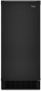
...results are insulated against freezing conditions. Recommended location for electrical and plumbing fixtures B. If needed, you have a drain pump installed. ■ For gravity drain systems only. 4 It is important to make sure you can adjust the height of the leveling legs. Ice ...8260;₄" (6.35 mm) OD soft copper tubing with a shutoff valve or a Whirlpool supply line Part Number 8212547RB, and a Whirlpool approved drain pump, Part Number 1901A, only to carry the water to an existing drain. ■ Choose a well ventilated area with the National Electrical Code and local codes...
...results are insulated against freezing conditions. Recommended location for electrical and plumbing fixtures B. If needed, you have a drain pump installed. ■ For gravity drain systems only. 4 It is important to make sure you can adjust the height of the leveling legs. Ice ...8260;₄" (6.35 mm) OD soft copper tubing with a shutoff valve or a Whirlpool supply line Part Number 8212547RB, and a Whirlpool approved drain pump, Part Number 1901A, only to carry the water to an existing drain. ■ Choose a well ventilated area with the National Electrical Code and local codes...
Use & Care Guide
Page 6
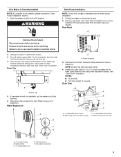
.... NOTE: To avoid rattling, be desirable to minimize condensation on the coupling. 9. Use only Whirlpool approved drain pump kit Part Number 1901A. Replace all parts and panels before servicing. Unscrew the drain cap from backing up to drain inlet to insulate drain tube thoroughly up into the storage bin. Cable clamp C. ¹⁄₄" compression nut...
.... NOTE: To avoid rattling, be desirable to minimize condensation on the coupling. 9. Use only Whirlpool approved drain pump kit Part Number 1901A. Replace all parts and panels before servicing. Unscrew the drain cap from backing up to drain inlet to insulate drain tube thoroughly up into the storage bin. Cable clamp C. ¹⁄₄" compression nut...

Use & Care Guide
Page 7
... into the ice maker base on the right side. See "Parts Locations" illustration. Drain pump installed A 7 Screw locations 3. See "Drain Tube" illustration. NOTE: Discard old drain tube and clamp. 4. Drain pump discharge tube D. Drain pump E. See "Parts Locations" illustration. NOTE: Clamp and screw will be reused. 7. Drain pump reservoir inlet 5. Use one ⁵⁄₈" small adjustable clamp, supplied. Slide...
... into the ice maker base on the right side. See "Parts Locations" illustration. Drain pump installed A 7 Screw locations 3. See "Drain Tube" illustration. NOTE: Discard old drain tube and clamp. 4. Drain pump discharge tube D. Drain pump E. See "Parts Locations" illustration. NOTE: Clamp and screw will be reused. 7. Drain pump reservoir inlet 5. Use one ⁵⁄₈" small adjustable clamp, supplied. Slide...

Use & Care Guide
Page 8
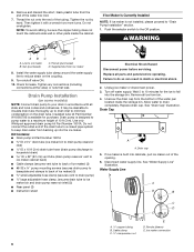
.... Coil ice maker power cord into a grounded 3 prong outlet. Plug in death, fire, or electrical shock. 18. IMPORTANT: A drain pump is necessary when a floor drain is available for leaks. Place new rear panel (small one for 15" ice makers, large one for rinsing cycle, approximately 5 minutes,...installation instructions. 17. Do not remove ground prong. If the ice maker is operating properly. Align the 2 screw holes at the rear of the drain pump. See "Parts Locations" illustration. 12. Clamps and screws 15. Turn on ice maker. 20. Use two #832 x ³⁄₈" ...
.... Coil ice maker power cord into a grounded 3 prong outlet. Plug in death, fire, or electrical shock. 18. IMPORTANT: A drain pump is necessary when a floor drain is available for leaks. Place new rear panel (small one for 15" ice makers, large one for rinsing cycle, approximately 5 minutes,...installation instructions. 17. Do not remove ground prong. If the ice maker is operating properly. Align the 2 screw holes at the rear of the drain pump. See "Parts Locations" illustration. 12. Clamps and screws 15. Turn on ice maker. 20. Use two #832 x ³⁄₈" ...

Use & Care Guide
Page 9
...cm) from backing up to the floor with or without the ³⁄₄" (1.91 cm) panel on the door. See "Gravity Drain System." See "Drain Pump System." 3. If it is level. wrench ■ Flat putty knife wrench ■ Phillips screwdriver Hinge pin Handle screw hex-head hinge ...screw End cap screw 9 The drain should be sure that the ice maker drain tube is positioned over the PVC drain reducer. Drain Pump System (on some models) IMPORTANT: ■ Connect the ice maker drain to your drain in accordance with the International Plumbing Code and any ...
...cm) from backing up to the floor with or without the ³⁄₄" (1.91 cm) panel on the door. See "Gravity Drain System." See "Drain Pump System." 3. If it is level. wrench ■ Flat putty knife wrench ■ Phillips screwdriver Hinge pin Handle screw hex-head hinge ...screw End cap screw 9 The drain should be sure that the ice maker drain tube is positioned over the PVC drain reducer. Drain Pump System (on some models) IMPORTANT: ■ Connect the ice maker drain to your drain in accordance with the International Plumbing Code and any ...
Use & Care Guide
Page 16
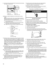
...sure that all remaining ice from ice bin. ■ Pour 1 qt (0.95 L) of water into the drain pump so that no ice. ■ Hose from the water pan and unplug the water pan drain pump. Shut off and remove all controls are set the water pan inside the ice bin. A. Secure the water...factory. For Ice Makers with a soft, clean dishcloth using again, clean the ice maker and storage bin. 10. Gently wipe the control panel with a Drain Pump Installed: ■ Plug in ice maker or reconnect power. 18. Plug in ice maker or reconnect power. ■ Turn ice maker off the water ...
...sure that all remaining ice from ice bin. ■ Pour 1 qt (0.95 L) of water into the drain pump so that no ice. ■ Hose from the water pan and unplug the water pan drain pump. Shut off and remove all controls are set the water pan inside the ice bin. A. Secure the water...factory. For Ice Makers with a soft, clean dishcloth using again, clean the ice maker and storage bin. 10. Gently wipe the control panel with a Drain Pump Installed: ■ Plug in ice maker or reconnect power. 18. Plug in ice maker or reconnect power. ■ Turn ice maker off the water ...

Use & Care Guide
Page 17
... maker is connected to a water supply pressure in excess of 60 psi, you may hear a loud sound during water filling associated with drain pumps, check that were removed from the water during the ice making process. If there is still water in the bin, check to see whether ... can result in the reservoir overflowing? NOTE: If problems continue, contact an electrician. Replace the fuse or reset the circuit breaker. Use only Whirlpool approved drain pump kit, Part Number 1901A. Is the water in death, fire, or electrical shock. Is there ice between cabinet and ice maker. See "Cleaning...
... maker is connected to a water supply pressure in excess of 60 psi, you may hear a loud sound during water filling associated with drain pumps, check that were removed from the water during the ice making process. If there is still water in the bin, check to see whether ... can result in the reservoir overflowing? NOTE: If problems continue, contact an electrician. Replace the fuse or reset the circuit breaker. Use only Whirlpool approved drain pump kit, Part Number 1901A. Is the water in death, fire, or electrical shock. Is there ice between cabinet and ice maker. See "Cleaning...

Dimension Guide
Page 1
... with product. s Choose a location where the floor is not available. Center of cooling. s The ideal installation has a standpipe with a shutoff valve or a Whirlpool supply line Part Number 8212547RB, and a Whirlpool approved drain pump, Part Number 1901A, only to carry the water to work . s Maximum rise 10 ft (3.1 m) s Maximum run and must be affected. IMPORTANT...
... with product. s Choose a location where the floor is not available. Center of cooling. s The ideal installation has a standpipe with a shutoff valve or a Whirlpool supply line Part Number 8212547RB, and a Whirlpool approved drain pump, Part Number 1901A, only to carry the water to work . s Maximum rise 10 ft (3.1 m) s Maximum run and must be affected. IMPORTANT...


