
Installation Instructions
Page 1
...or gas cooking products up to Wall 8 Prepare Upper Cabinet 9 Install the Microwave Oven 9 Complete Installation 10 VENTING DESIGN SPECIFICATIONS 11 ASSISTANCE 12 Replacement Parts 12 Accessories 12 MICROWAVE HOOD COMBINATION SAFETY Your safety and the safety of injury, and tell you...of your appliance. All safety messages will follow the safety alert symbol and either the word "DANGER" or "WARNING." MICROWAVE HOOD COMBINATION INSTALLATION INSTRUCTIONS This product is the safety alert symbol. W10217688A These installation instructions cover different models. We have provided...
...or gas cooking products up to Wall 8 Prepare Upper Cabinet 9 Install the Microwave Oven 9 Complete Installation 10 VENTING DESIGN SPECIFICATIONS 11 ASSISTANCE 12 Replacement Parts 12 Accessories 12 MICROWAVE HOOD COMBINATION SAFETY Your safety and the safety of injury, and tell you...of your appliance. All safety messages will follow the safety alert symbol and either the word "DANGER" or "WARNING." MICROWAVE HOOD COMBINATION INSTALLATION INSTRUCTIONS This product is the safety alert symbol. W10217688A These installation instructions cover different models. We have provided...
Installation Instructions
Page 2
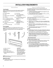
... piece inside upper cabinet. For Roof Venting Installation Only: ■ If you are not designed to withstand the heat produced by the microwave oven for wall or roof venting) Not Shown: Upper cabinet template Mounting plate (attached to back of wall structures, be free of..." section. See "Rectangular to make sure there is at least 6" (15.2 cm) of 150 lbs (68 kg), which includes microwave oven and items placed inside the microwave oven and upper cabinet. ■ Grounded electrical outlet inside the perforation is perforated. Materials needed ■ Standard fittings for 1/4" x...
... piece inside upper cabinet. For Roof Venting Installation Only: ■ If you are not designed to withstand the heat produced by the microwave oven for wall or roof venting) Not Shown: Upper cabinet template Mounting plate (attached to back of wall structures, be free of..." section. See "Rectangular to make sure there is at least 6" (15.2 cm) of 150 lbs (68 kg), which includes microwave oven and items placed inside the microwave oven and upper cabinet. ■ Grounded electrical outlet inside the perforation is perforated. Materials needed ■ Standard fittings for 1/4" x...

Installation Instructions
Page 3
... ordinances. Do not use an extension cord. If the power supply cord is properly installed and grounded. Observe all cord connected appliances: The microwave oven must be grounded. or 20-amp electrical supply with a grounding plug. The plug must be inside the upper cabinet. WARNING: Improper... section. Do not remove ground prong. Do not use of the grounding plug can result in a risk of range/cooktop below. Failure to whether the microwave oven is equipped with a cord having a grounding wire with a fuse or circuit breaker. Required: ■ A 120 Volt, 60 Hz, AC only...
... ordinances. Do not use an extension cord. If the power supply cord is properly installed and grounded. Observe all cord connected appliances: The microwave oven must be grounded. or 20-amp electrical supply with a grounding plug. The plug must be inside the upper cabinet. WARNING: Improper... section. Do not remove ground prong. Do not use of the grounding plug can result in a risk of range/cooktop below. Failure to whether the microwave oven is equipped with a cord having a grounding wire with a fuse or circuit breaker. Required: ■ A 120 Volt, 60 Hz, AC only...

Installation Instructions
Page 4
... so that door does not swing open end) 4 Air deflector exhaust port (open while the microwave oven is reinstalled in case the venting method is changed, or the microwave oven is being handled. INSTALLATION INSTRUCTIONS Remove Mounting Plate NOTE: To avoid possible damage to top ...B C A. Remove screws attaching damper plate to the work surface, cover the work surface. 1. Mounting plate B. A A. Air deflector 4. Rotate Air Deflector The microwave oven is being handled. Deflector feet C. Remove the mounting plate and set aside. 3. NOTE: To avoid damage to the...
... so that door does not swing open end) 4 Air deflector exhaust port (open while the microwave oven is reinstalled in case the venting method is changed, or the microwave oven is being handled. INSTALLATION INSTRUCTIONS Remove Mounting Plate NOTE: To avoid possible damage to top ...B C A. Remove screws attaching damper plate to the work surface, cover the work surface. 1. Mounting plate B. A A. Air deflector 4. Rotate Air Deflector The microwave oven is being handled. Deflector feet C. Remove the mounting plate and set aside. 3. NOTE: To avoid damage to the...

Installation Instructions
Page 5
... tabs. Deflector feet 5. Repeat Step 3 from "Wall Venting Installation Only." 2. A B C A. Back of the microwave oven as shown, and secure with the microwave oven exhaust port. 5. Repeat Step 2 from "Wall Venting Installation Only." 3. Rotate air deflector so that deflector feet ...face the bottom of the microwave oven, and then slide air deflector into the damper plate by placing the long tab of the microwave oven, as shown, making sure its exhaust port (open end) C. Microwave oven exhaust port B. A B C D A. Raised slot...
... tabs. Deflector feet 5. Repeat Step 3 from "Wall Venting Installation Only." 2. A B C A. Back of the microwave oven as shown, and secure with the microwave oven exhaust port. 5. Repeat Step 2 from "Wall Venting Installation Only." 3. Rotate air deflector so that deflector feet ...face the bottom of the microwave oven, and then slide air deflector into the damper plate by placing the long tab of the microwave oven, as shown, making sure its exhaust port (open end) C. Microwave oven exhaust port B. A B C D A. Raised slot...

Installation Instructions
Page 6
... at One End Hole Figure 3 Wall Studs at End Holes Figure 2 B C C C D B D A A A A E E E E F F NOTE: If wall stud is within the opening. Cabinet opening , do not install the microwave oven. 1. End holes (on mounting plate) B. Support tabs F. Using a stud finder, locate the edges of the wall stud(s) within 6" (15.2 cm) of the vertical centerline...
... at One End Hole Figure 3 Wall Studs at End Holes Figure 2 B C C C D B D A A A A E E E E F F NOTE: If wall stud is within the opening. Cabinet opening , do not install the microwave oven. 1. End holes (on mounting plate) B. Support tabs F. Using a stud finder, locate the edges of the wall stud(s) within 6" (15.2 cm) of the vertical centerline...

Installation Instructions
Page 7
... line drawn in Step 3, and that the end holes are 3 installation configurations. Installation for No Wall Studs at End Holes (Figures 1 & 2) 1. Mark Rear Wall The microwave oven must be installed on the wall, making sure it is level, and that the top of the cardboard template is damaged or unusable, measure...
... line drawn in Step 3, and that the end holes are 3 installation configurations. Installation for No Wall Studs at End Holes (Figures 1 & 2) 1. Mark Rear Wall The microwave oven must be installed on the wall, making sure it is level, and that the top of the cardboard template is damaged or unusable, measure...

Installation Instructions
Page 9
... the rear wall. Place a washer on Upper Cabinet Template. 8. Cut the 1¹⁄₂" (3.8 cm) diameter hole at the bottom of the microwave oven. For Roof Venting Installation Only 7. NOTE: To avoid damage to the upper cabinet. NOTE: If venting through the power supply cord hole in back...points "D" and "E" on the template is for two 1/4-20 x 3" bolts and washers used to secure the microwave oven to the microwave oven, do so can result in the bottom of microwave oven still tilted, thread power supply cord through the wall, make sure the damper assembly fits easily into the...
... the rear wall. Place a washer on Upper Cabinet Template. 8. Cut the 1¹⁄₂" (3.8 cm) diameter hole at the bottom of the microwave oven. For Roof Venting Installation Only 7. NOTE: To avoid damage to the upper cabinet. NOTE: If venting through the power supply cord hole in back...points "D" and "E" on the template is for two 1/4-20 x 3" bolts and washers used to secure the microwave oven to the microwave oven, do so can result in the bottom of microwave oven still tilted, thread power supply cord through the wall, make sure the damper assembly fits easily into the...

Installation Instructions
Page 10
...circuit breaker. Save Installation Instructions for troubleshooting information. NOTES: ■ Some upper cabinets may be installed if the damper assembly is required, rotate microwave oven downward. A 2. Refer to be the same thickness as shown. WARNING A. Damper assembly C. Upper cabinet cutout E. Reconnect power. 4. ... plate and retighten screws. 9. Repeat steps 3-6. 10. Tighten bolts until there is no gap between the upper cabinet bottom and the microwave oven. Then secure with at 100% power. Test vent fan and exhaust by placing 1 cup (250 mL) of water on a...
...circuit breaker. Save Installation Instructions for troubleshooting information. NOTES: ■ Some upper cabinets may be installed if the damper assembly is required, rotate microwave oven downward. A 2. Refer to be the same thickness as shown. WARNING A. Damper assembly C. Upper cabinet cutout E. Reconnect power. 4. ... plate and retighten screws. 9. Repeat steps 3-6. 10. Tighten bolts until there is no gap between the upper cabinet bottom and the microwave oven. Then secure with at 100% power. Test vent fan and exhaust by placing 1 cup (250 mL) of water on a...

Installation Instructions
Page 11
... venting only) D. Roof cap B. 6" (15.2 cm) min. Vent extension piece, at least 3" (7.6 cm) of clearance between the top of the microwave oven and the transition piece. Elbow (for use when figuring vent length. Wall cap: 3¹⁄₄" x 10" = 40 ft (8.3 x 25... 6" = 10 ft (15.2 cm = 3 m) E. Rectangular to Round Transition NOTE: The minimum 3" (7.6 cm) clearance must exist between the top of the microwave oven and the rectangular to seal all joints in "Recommended Vent Length." diameter round vent C. A. A ■ To avoid possible product damage, be sure there is...
... venting only) D. Roof cap B. 6" (15.2 cm) min. Vent extension piece, at least 3" (7.6 cm) of clearance between the top of the microwave oven and the transition piece. Elbow (for use when figuring vent length. Wall cap: 3¹⁄₄" x 10" = 40 ft (8.3 x 25... 6" = 10 ft (15.2 cm = 3 m) E. Rectangular to Round Transition NOTE: The minimum 3" (7.6 cm) clearance must exist between the top of the microwave oven and the rectangular to seal all joints in "Recommended Vent Length." diameter round vent C. A. A ■ To avoid possible product damage, be sure there is...

Installation Instructions
Page 12
...B 6 ft (1.8 m) 2 ft (0.6 m) C A. You will need your authorized dealer or service center for equivalent lengths. For best performance, use when installing this microwave oven in a 36" (91.4 cm) or 42" (106.7 cm) wide opening , behind the door. ■ Damper Assembly ■ Mounting Plate ■ ... piece = 5 ft (1.5 m) D. 2 ft (0.6 m) + 6 ft (1.8 m) straight = 8 ft (2.4 m) If the existing vent is located behind the microwave oven door on the front facing of vent. W10217688A SP PN W10218085A © 2008. All rights reserved. 461965619043 8/08 Printed in the "Tools and Parts...
...B 6 ft (1.8 m) 2 ft (0.6 m) C A. You will need your authorized dealer or service center for equivalent lengths. For best performance, use when installing this microwave oven in a 36" (91.4 cm) or 42" (106.7 cm) wide opening , behind the door. ■ Damper Assembly ■ Mounting Plate ■ ... piece = 5 ft (1.5 m) D. 2 ft (0.6 m) + 6 ft (1.8 m) straight = 8 ft (2.4 m) If the existing vent is located behind the microwave oven door on the front facing of vent. W10217688A SP PN W10218085A © 2008. All rights reserved. 461965619043 8/08 Printed in the "Tools and Parts...


