
Installation Instructions
Page 1
... alerts you to Wall 8 Prepare Upper Cabinet 9 Install the Microwave Oven 9 Complete Installation 10 VENTING DESIGN SPECIFICATIONS 11 ASSISTANCE 12 Replacement Parts 12 Accessories 12 MICROWAVE HOOD COMBINATION SAFETY Your safety and the safety of your appliance...follow instructions. See "Installation Requirements" section for use above electric or gas cooking products up to reduce the chance of Contents MICROWAVE HOOD COMBINATION SAFETY 1 INSTALLATION REQUIREMENTS 2 Tools and Parts 2 Remove Cardboard Template 2 Location Requirements 2 Product Dimensions 3 Electrical ...
... alerts you to Wall 8 Prepare Upper Cabinet 9 Install the Microwave Oven 9 Complete Installation 10 VENTING DESIGN SPECIFICATIONS 11 ASSISTANCE 12 Replacement Parts 12 Accessories 12 MICROWAVE HOOD COMBINATION SAFETY Your safety and the safety of your appliance...follow instructions. See "Installation Requirements" section for use above electric or gas cooking products up to reduce the chance of Contents MICROWAVE HOOD COMBINATION SAFETY 1 INSTALLATION REQUIREMENTS 2 Tools and Parts 2 Remove Cardboard Template 2 Location Requirements 2 Product Dimensions 3 Electrical ...
Installation Instructions
Page 2
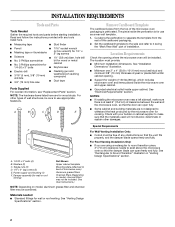
...D. 1/4" x 2" lag screws (2) E. See "Venting Design Specifications" section. Remove Cardboard Template The cardboard piece from the rest of the microwave oven packaging is perforated. Cut along the perforation to separate the template from the top of the cardboard packaging. 2. The location must be ...x 4" (50.8 x 101.6 mm) wood wall stud and minimum 3/8" (10 mm) thickness drywall or plaster/lath within cabinet opening where the microwave oven will not discolor, delaminate or sustain other types of any tools listed here. ■ Measuring tape ■ Stud finder ■ Pencil ...
...D. 1/4" x 2" lag screws (2) E. See "Venting Design Specifications" section. Remove Cardboard Template The cardboard piece from the rest of the microwave oven packaging is perforated. Cut along the perforation to separate the template from the top of the cardboard packaging. 2. The location must be ...x 4" (50.8 x 101.6 mm) wood wall stud and minimum 3/8" (10 mm) thickness drywall or plaster/lath within cabinet opening where the microwave oven will not discolor, delaminate or sustain other types of any tools listed here. ■ Measuring tape ■ Stud finder ■ Pencil ...

Installation Instructions
Page 3
... grounded 3 prong outlet. Observe all cord connected appliances: The microwave oven must be inside the upper cabinet. A. 2" x 4" wall stud B. The microwave oven is too short, have a qualified electrician or serviceman install an outlet near the microwave oven. See "Electrical Requirements" section. Required: ■ A...an extension cord. Recommended: ■ A time-delay fuse or time-delay circuit breaker. ■ A separate circuit serving only this microwave oven. or 20-amp electrical supply with a grounding plug. Do not use of the grounding plug can result in a risk of ...
... grounded 3 prong outlet. Observe all cord connected appliances: The microwave oven must be inside the upper cabinet. A. 2" x 4" wall stud B. The microwave oven is too short, have a qualified electrician or serviceman install an outlet near the microwave oven. See "Electrical Requirements" section. Required: ■ A...an extension cord. Recommended: ■ A time-delay fuse or time-delay circuit breaker. ■ A separate circuit serving only this microwave oven. or 20-amp electrical supply with a grounding plug. Do not use of the grounding plug can result in a risk of ...

Installation Instructions
Page 4
... wall or roof venting, changes must be used. Remove screws attaching damper plate to top of the microwave oven as shown, making sure its exhaust port (open end) 4 Back of microwave oven. Damper plate 2. Keep damper plate and screws together and set aside. A A. Remove any remaining...avoid damage to back so that door does not swing open while the microwave oven is being handled. Rotate Air Deflector The microwave oven is reinstalled in case the venting method is changed, or the microwave oven is set for recirculation installation. Retaining tabs B. Remove the mounting ...
... wall or roof venting, changes must be used. Remove screws attaching damper plate to top of the microwave oven as shown, making sure its exhaust port (open end) 4 Back of microwave oven. Damper plate 2. Keep damper plate and screws together and set aside. A A. Remove any remaining...avoid damage to back so that door does not swing open while the microwave oven is being handled. Rotate Air Deflector The microwave oven is reinstalled in case the venting method is changed, or the microwave oven is set for recirculation installation. Retaining tabs B. Remove the mounting ...

Installation Instructions
Page 5
... Damper assembly D. Damper plate C. Repeat Step 2 from "Wall Venting Installation Only." 2. Rotate air deflector so that deflector feet face the bottom of the microwave oven, and then slide air deflector into the damper plate by placing the long tab of the assembly under the retaining tabs. Slide damper plate... under the raised slot of the microwave oven, as shown, making sure its exhaust port (open end) C. A A. Damper plate C. Retaining tabs 5 Raised slot 6. Repeat ...
... Damper assembly D. Damper plate C. Repeat Step 2 from "Wall Venting Installation Only." 2. Rotate air deflector so that deflector feet face the bottom of the microwave oven, and then slide air deflector into the damper plate by placing the long tab of the assembly under the retaining tabs. Slide damper plate... under the raised slot of the microwave oven, as shown, making sure its exhaust port (open end) C. A A. Damper plate C. Retaining tabs 5 Raised slot 6. Repeat ...

Installation Instructions
Page 6
...: If no wall studs exist within the opening vertical centerline C. Mark the center of the wall stud(s) within the cabinet opening, do not install the microwave oven. 1.
...: If no wall studs exist within the opening vertical centerline C. Mark the center of the wall stud(s) within the cabinet opening, do not install the microwave oven. 1.

Installation Instructions
Page 7
... mark. 10. Holding the cardboard template in place, mark both end holes. Draw the 2 vertical, plumb lines down from the centerline. 5. Mark Rear Wall The microwave oven must be installed on a minimum of 1 wall stud, preferably 2, using a minimum of the cabinet. ■ If the cardboard template is damaged or unusable, measure...
... mark. 10. Holding the cardboard template in place, mark both end holes. Draw the 2 vertical, plumb lines down from the centerline. 5. Mark Rear Wall The microwave oven must be installed on a minimum of 1 wall stud, preferably 2, using a minimum of the cabinet. ■ If the cardboard template is damaged or unusable, measure...

Installation Instructions
Page 9
...and "E" on support tabs at points "D" and "E" on the rear wall. Make sure the 10 26.5 cm) dimension from upper cabinet. 3. Handle the microwave oven gently. 1. NOTE: If upper cabinet is maintained. Power supply cord bushing 6. Mounting plate B. Support tabs 4. NOTE: If venting through the power supply... supply cord through the wall, make sure the damper assembly fits easily into the upper cabinet align with tape or thumbtacks. Make sure the microwave oven door is being handled. Upper-cabinet template D E 10 10 (26.5 cm) F (26.5 cm) G 5. B A A. NOTE: To avoid...
...and "E" on support tabs at points "D" and "E" on the rear wall. Make sure the 10 26.5 cm) dimension from upper cabinet. 3. Handle the microwave oven gently. 1. NOTE: If upper cabinet is maintained. Power supply cord bushing 6. Mounting plate B. Support tabs 4. NOTE: If venting through the power supply... supply cord through the wall, make sure the damper assembly fits easily into the upper cabinet align with tape or thumbtacks. Make sure the microwave oven door is being handled. Upper-cabinet template D E 10 10 (26.5 cm) F (26.5 cm) G 5. B A A. NOTE: To avoid...

Installation Instructions
Page 10
... removed in death, fire, or electrical shock. 2. Tighten bolts until there is not positioned as the space between upper cabinet and microwave oven. To avoid warping, wood filler blocks may be installed if the damper assembly is no gap between the upper cabinet bottom and the... upper cabinet into a grounded 3 prong outlet. ■ See the User Instructions for future use an extension cord. NOTE: The screw cannot be added. Plug microwave oven into a grounded 3 prong outlet. Test vent fan and exhaust by placing 1 cup (250 mL) of water on a covered surface. 8. If the problem...
... removed in death, fire, or electrical shock. 2. Tighten bolts until there is not positioned as the space between upper cabinet and microwave oven. To avoid warping, wood filler blocks may be installed if the damper assembly is no gap between the upper cabinet bottom and the... upper cabinet into a grounded 3 prong outlet. ■ See the User Instructions for future use an extension cord. NOTE: The screw cannot be added. Plug microwave oven into a grounded 3 prong outlet. Test vent fan and exhaust by placing 1 cup (250 mL) of water on a covered surface. 8. If the problem...

Installation Instructions
Page 11
... garages. If venting through the wall, be sure there is at least 3" (7.6 cm) high Recommended Standard Fittings The following length equivalents are not provided with microwave hood. diameter round vent C. Roof cap: 3¹⁄₄" x 10" = 24 ft (8.3 x 25.4 cm = 7.3 m) C. 90° elbow: 3&#... rectangular to Round Transition" illustration. Vent extension piece, at least 3" (7.6 cm) of clearance between the top of the microwave oven and the rectangular to open fully. VENTING DESIGN SPECIFICATIONS This section is intended for use when figuring vent length. NOTES:...
... garages. If venting through the wall, be sure there is at least 3" (7.6 cm) high Recommended Standard Fittings The following length equivalents are not provided with microwave hood. diameter round vent C. Roof cap: 3¹⁄₄" x 10" = 24 ft (8.3 x 25.4 cm = 7.3 m) C. 90° elbow: 3&#... rectangular to Round Transition" illustration. Vent extension piece, at least 3" (7.6 cm) of clearance between the top of the microwave oven and the rectangular to open fully. VENTING DESIGN SPECIFICATIONS This section is intended for use when figuring vent length. NOTES:...

Installation Instructions
Page 12
... Parts If any of each vent piece used in the User Instructions. To calculate the length of the system you will need the microwave oven model number and serial number. In addition, a rectangular 3" (7.6 cm) extension vent between the damper assembly and rectangular to ... ft (6.1 m) B. 1 wall cap = 40 ft (12.2 m) C. 1 rectangular to round transition piece must not exceed the equivalent of 140 ft (42.7 m) for either type of the microwave oven opening . See the following examples: 3¹⁄₄" x 10" (8.3 x 25.4 cm) vent system = 73 ft (22.2 m) total A B 6 ft (1.8 m) 2 ft ...
... Parts If any of each vent piece used in the User Instructions. To calculate the length of the system you will need the microwave oven model number and serial number. In addition, a rectangular 3" (7.6 cm) extension vent between the damper assembly and rectangular to ... ft (6.1 m) B. 1 wall cap = 40 ft (12.2 m) C. 1 rectangular to round transition piece must not exceed the equivalent of 140 ft (42.7 m) for either type of the microwave oven opening . See the following examples: 3¹⁄₄" x 10" (8.3 x 25.4 cm) vent system = 73 ft (22.2 m) total A B 6 ft (1.8 m) 2 ft ...


