Installation Instructions
Page 2
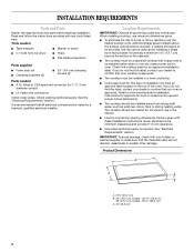
... dimensions that projects horizontally a minimum of 5" (12.7 cm) beyond the bottom of the cabinets. ■ The cooktop must be installed in undercounter use and proper cutout dimensions. ■ The cooktop should be made by installing a range hood that are minimum clearances and provide 0" (0 cm) clearance. ■ Grounded electrical supply is approved...
... dimensions that projects horizontally a minimum of 5" (12.7 cm) beyond the bottom of the cabinets. ■ The cooktop must be installed in undercounter use and proper cutout dimensions. ■ The cooktop should be made by installing a range hood that are minimum clearances and provide 0" (0 cm) clearance. ■ Grounded electrical supply is approved...
Installation Instructions
Page 3
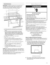
...covered by dashed box above) C. 30" (76.2 cm) minimum clearance between back wall and countertop NOTES: After making the countertop cutout, some installations may require notching down the base cabinet side walls to the top of electrical connection you are adequate and in conformance ...with local codes. Check with not less than the cutout. Combustible area above countertop (shown by not less than ¹⁄₄" [0.6 cm] flame retardant millboard covered with a qualified electrical...
...covered by dashed box above) C. 30" (76.2 cm) minimum clearance between back wall and countertop NOTES: After making the countertop cutout, some installations may require notching down the base cabinet side walls to the top of electrical connection you are adequate and in conformance ...with local codes. Check with not less than the cutout. Combustible area above countertop (shown by not less than ¹⁄₄" [0.6 cm] flame retardant millboard covered with a qualified electrical...
Installation Instructions
Page 4
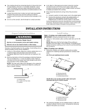
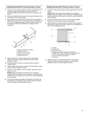
... Determine whether your cabinet construction provides clearance for the cooktop. Clamping bracket B. A listed conduit connector is placed into the cutout. Remove one strip at the cooktop. ■ If the house has aluminum wiring, follow the procedure below: 1. Style... knob models B C A B C A. Attachment screw C. Connect a section of copper wire using the foam end posts from cutout to the pigtail leads. 2. Avoid drilling into the cutout. Cooktop base bottom All 36" (91.4 cm) models and 30" (76.2 cm) touchactivated electronic control models A B C...
... Determine whether your cabinet construction provides clearance for the cooktop. Clamping bracket B. A listed conduit connector is placed into the cutout. Remove one strip at the cooktop. ■ If the house has aluminum wiring, follow the procedure below: 1. Style... knob models B C A B C A. Attachment screw C. Connect a section of copper wire using the foam end posts from cutout to the pigtail leads. 2. Avoid drilling into the cutout. Cooktop base bottom All 36" (91.4 cm) models and 30" (76.2 cm) touchactivated electronic control models A B C...
Installation Instructions
Page 5
... brackets so that the front edge of the countertop. Cooktop base C. Countertop 4. Remove the attachment screws for the bracket locations from cutout to Countertop") F. If repositioning is parallel to the front edge of 2½" (6.4 cm) clamping screws. Select bracket mounting holes ...for the selected bracket locations from the cooktop for illustration of 2½" (6.4 cm) clamping screws. If repositioning is placed in cutout. Clamping bracket (extends far enough beyond cooktop base to allow the bracket to Countertop" section for the installation of clamping screw ...
... brackets so that the front edge of the countertop. Cooktop base C. Countertop 4. Remove the attachment screws for the bracket locations from cutout to Countertop") F. If repositioning is parallel to the front edge of 2½" (6.4 cm) clamping screws. Select bracket mounting holes ...for the selected bracket locations from the cooktop for illustration of 2½" (6.4 cm) clamping screws. If repositioning is placed in cutout. Clamping bracket (extends far enough beyond cooktop base to allow the bracket to Countertop" section for the installation of clamping screw ...