
Owners Manual
Page 2
TOUCH-ACTIVATED CONTROLS.....5 Dual/Triple Element 6 All Off/Lock 6 Keep Warm 7 PARTS AND FEATURES - COMMANDES À BOUTONS ROTATIFS 24 Élément à double/triple circuit 25 Élément de liaison 26 Él&#...immediately follow instructions. KNOB CONTROLS 9 Dual/Triple-Circuit Element 9 Bridge Element 10 Warm Zone Element 10 ACCUSIMMER® Feature 11 COOKTOP USE 11 Ceramic Glass 11 Home Canning 12 Cookware 12 COOKTOP CARE 13 General Cleaning 13 TROUBLESHOOTING 14 ASSISTANCE OR SERVICE 15 In the U.S.A 15 Accessories 15 In Canada 15 WARRANTY 16 ...
TOUCH-ACTIVATED CONTROLS.....5 Dual/Triple Element 6 All Off/Lock 6 Keep Warm 7 PARTS AND FEATURES - COMMANDES À BOUTONS ROTATIFS 24 Élément à double/triple circuit 25 Élément de liaison 26 Él&#...immediately follow instructions. KNOB CONTROLS 9 Dual/Triple-Circuit Element 9 Bridge Element 10 Warm Zone Element 10 ACCUSIMMER® Feature 11 COOKTOP USE 11 Ceramic Glass 11 Home Canning 12 Cookware 12 COOKTOP CARE 13 General Cleaning 13 TROUBLESHOOTING 14 ASSISTANCE OR SERVICE 15 In the U.S.A 15 Accessories 15 In Canada 15 WARRANTY 16 ...
Owners Manual
Page 3
... in the manual. If cooktop should not be allowed to sit or stand on Broken Cooktop - For units with one or more surface units of different size. Flammable materials should break, cleaning solutions and spillovers may result in use of undersized utensils will also improve efficiency. ■ Never Leave Surface Units Unattended at High Heat Settings - Only certain types of glass, glass/ceramic, ceramic, earthenware, or...
... in the manual. If cooktop should not be allowed to sit or stand on Broken Cooktop - For units with one or more surface units of different size. Flammable materials should break, cleaning solutions and spillovers may result in use of undersized utensils will also improve efficiency. ■ Never Leave Surface Units Unattended at High Heat Settings - Only certain types of glass, glass/ceramic, ceramic, earthenware, or...
Owners Manual
Page 5
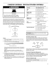
... a power failure occurs, the Hot Surface Indicator Light will glow as long as any of the internal components during use to turn off . 3. Hot Surface Indicator Light The Hot Surface Indicator Light is located in death or fire. To change the temperature setting while cooking, touch the ON keypad for the desired element. Component Temperature Management The cooktop regulates the temperature of the elements are melting foods such as a guide when setting heat levels. When any surface cooking...
... a power failure occurs, the Hot Surface Indicator Light will glow as long as any of the internal components during use to turn off . 3. Hot Surface Indicator Light The Hot Surface Indicator Light is located in death or fire. To change the temperature setting while cooking, touch the ON keypad for the desired element. Component Temperature Management The cooktop regulates the temperature of the elements are melting foods such as a guide when setting heat levels. When any surface cooking...
Owners Manual
Page 6
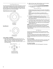
... element will glow to turn off the downdraft exhaust system and all heating zones will use of heating zones being used and those burner areas will remember the setting from the last time it was used while cooking, touch ON once then again while the Power Level 1 light is blinking. Dual size C. To reduce the number of the surface cooking areas. While the Power Level 1 light is locked out, the surface cooking...
... element will glow to turn off the downdraft exhaust system and all heating zones will use of heating zones being used and those burner areas will remember the setting from the last time it was used while cooking, touch ON once then again while the Power Level 1 light is blinking. Dual size C. To reduce the number of the surface cooking areas. While the Power Level 1 light is locked out, the surface cooking...
Owners Manual
Page 8
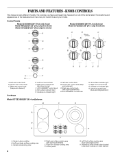
...Control panel E G. Model and serial number plate (located underneath cooktop on indicator light A. Right rear control knob (with triple-size element) E. Left front control knob (dual-size bridge element) A H G A. Left rear single surface cooking area C. Right front surface cooking area F. Left front surface cooking area (dual-size bridge burner) H. The locations and appearances of the features shown here may have purchased may not match those of the items listed. Right rear control knob (keep warm element) C. Cooktop on metal cabinet) ACCUSIMMER® control knob Model...
...Control panel E G. Model and serial number plate (located underneath cooktop on indicator light A. Right rear control knob (with triple-size element) E. Left front control knob (dual-size bridge element) A H G A. Left rear single surface cooking area C. Right front surface cooking area F. Left front surface cooking area (dual-size bridge burner) H. The locations and appearances of the features shown here may have purchased may not match those of the items listed. Right rear control knob (keep warm element) C. Cooktop on metal cabinet) ACCUSIMMER® control knob Model...
Owners Manual
Page 11
... element is on the triple circuit element when medium or high simmer is set on the cooktop. Select Low for a low simmer or when using lids and medium for a high simmer or when not using a scraper while the surface is set on . This is normal. The ACCUSIMMER® control knob has two settings: Simmer and Normal. COOKTOP USE Ceramic Glass (on some models) The ACCUSIMMER® feature setting is an adjustable heat setting for the surface of light colored ceramic glass...
... element is on the triple circuit element when medium or high simmer is set on the cooktop. Select Low for a low simmer or when using lids and medium for a high simmer or when not using a scraper while the surface is set on . This is normal. The ACCUSIMMER® control knob has two settings: Simmer and Normal. COOKTOP USE Ceramic Glass (on some models) The ACCUSIMMER® feature setting is an adjustable heat setting for the surface of light colored ceramic glass...
Owners Manual
Page 12
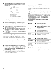
.... ■ On coil element models, the installation of a Canning Unit Kit is not installed, the life of the coil element will take on the properties of aluminum or copper on the grate or largest surface cooking area or element. Ceramic or Ceramic glass ■ Follow manufacturer's instructions. ■ Heats slowly, but unevenly. ■ A core or base of aluminum. B A C A. Use the following chart as its base material. Stainless steel ■ Heats quickly, but unevenly. ■...
.... ■ On coil element models, the installation of a Canning Unit Kit is not installed, the life of the coil element will take on the properties of aluminum or copper on the grate or largest surface cooking area or element. Ceramic or Ceramic glass ■ Follow manufacturer's instructions. ■ Heats slowly, but unevenly. ■ A core or base of aluminum. B A C A. Use the following chart as its base material. Stainless steel ■ Heats quickly, but unevenly. ■...
Owners Manual
Page 13
... from control panel to stainless steel surfaces, do not soak knobs. Do not use soap-filled scouring pads, abrasive cleaners, Cooktop Polishing Creme, steel-wool pads, gritty washcloths or some models) To avoid damage to remove. ■ Cooktop Polishing Creme and clean damp paper towel: Clean as soon as cooktop has cooled down . Rub creme into surface with damp paper towel. See "All Off/Lock" section. Hold scraper...
... from control panel to stainless steel surfaces, do not soak knobs. Do not use soap-filled scouring pads, abrasive cleaners, Cooktop Polishing Creme, steel-wool pads, gritty washcloths or some models) To avoid damage to remove. ■ Cooktop Polishing Creme and clean damp paper towel: Clean as soon as cooktop has cooled down . Rub creme into surface with damp paper towel. See "All Off/Lock" section. Hold scraper...
Owners Manual
Page 14
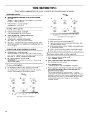
... control knob set correctly? Replace the fuse or reset the circuit breaker. Push in knob before turning to a setting. ■ Is the "All Off Lock" cooktop lockout set to blink on and off ? Excessive heat around cookware on and off , indicating that one or more than usual or some power levels do not perform as well as the surface cooking area, element or surface burner. Cooktop has flashing lights ■ Are the lights on the cooktop flashing on cooktop...
... control knob set correctly? Replace the fuse or reset the circuit breaker. Push in knob before turning to a setting. ■ Is the "All Off Lock" cooktop lockout set to blink on and off ? Excessive heat around cookware on and off , indicating that one or more than usual or some power levels do not perform as well as the surface cooking area, element or surface burner. Cooktop has flashing lights ■ Are the lights on the cooktop flashing on cooktop...
Owners Manual
Page 15
... States. Canning Unit Kit (coil element models) Order Part Number 242905 Cooktop Cleaner (ceramic glass models) Order Part Number 31464 Cooktop Protectant (ceramic glass models) Order Part Number 31463 Cooktop Care Kit (includes cleaner, protectant, and applicator pads) Order Part Number 31605 Cooktop Scraper (ceramic glass models) Order Part Number WA906B All-Purpose Appliance Cleaner Order Part Number 31682 In Canada Call the Whirlpool Canada LP Customer eXperience Centre toll free: 1-800-807-6777. Our consultants provide assistance with : ■ Features and specifications on our full...
... States. Canning Unit Kit (coil element models) Order Part Number 242905 Cooktop Cleaner (ceramic glass models) Order Part Number 31464 Cooktop Protectant (ceramic glass models) Order Part Number 31463 Cooktop Care Kit (includes cleaner, protectant, and applicator pads) Order Part Number 31605 Cooktop Scraper (ceramic glass models) Order Part Number WA906B All-Purpose Appliance Cleaner Order Part Number 31682 In Canada Call the Whirlpool Canada LP Customer eXperience Centre toll free: 1-800-807-6777. Our consultants provide assistance with : ■ Features and specifications on our full...
Owners Manual
Page 16
... service if your complete model number and serial number. Service calls to correct the installation of your major appliance, to parts or systems resulting from warranty coverage. 3. Damage resulting from your home of your sales slip together for Factory Specified Parts and repair labor to correct house wiring or plumbing. 2. Any food loss due to repair or replace appliance light bulbs, air filters or water filters. Repairs to instruct you need...
... service if your complete model number and serial number. Service calls to correct the installation of your major appliance, to parts or systems resulting from warranty coverage. 3. Damage resulting from your home of your sales slip together for Factory Specified Parts and repair labor to correct house wiring or plumbing. 2. Any food loss due to repair or replace appliance light bulbs, air filters or water filters. Repairs to instruct you need...
Installation Instructions
Page 1
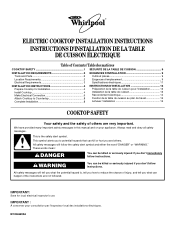
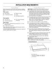
... pour consultation par l'inspecteur local des installations électriques. ® ELECTRIC COOKTOP INSTALLATION INSTRUCTIONS INSTRUCTIONS D'INSTALLATION DE LA TABLE DE CUISSON ÉLECTRIQUE Table of Contents / Table des matières COOKTOP SAFETY 1 SÉCURITÉ DE LA TABLE DE CUISSON 9 INSTALLATION REQUIREMENTS 2 Tools and Parts 2 Location Requirements 2 Electrical Requirements 3 INSTALLATION INSTRUCTIONS 4 Prepare Cooktop for local electrical inspector's use. WARNING You can happen if the instructions are very important. Always read...
... pour consultation par l'inspecteur local des installations électriques. ® ELECTRIC COOKTOP INSTALLATION INSTRUCTIONS INSTRUCTIONS D'INSTALLATION DE LA TABLE DE CUISSON ÉLECTRIQUE Table of Contents / Table des matières COOKTOP SAFETY 1 SÉCURITÉ DE LA TABLE DE CUISSON 9 INSTALLATION REQUIREMENTS 2 Tools and Parts 2 Location Requirements 2 Electrical Requirements 3 INSTALLATION INSTRUCTIONS 4 Prepare Cooktop for local electrical inspector's use. WARNING You can happen if the instructions are very important. Always read...
Installation Instructions
Page 2
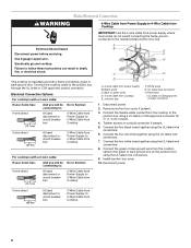
... conduit ■ UL listed wire connectors Check local codes. The cooktop should be installed in oven. Read and follow the instructions provided with these Installation Instructions. When installing cooktop, use and proper cutout dimensions. ■ The cooktop should be made by a licensed, qualified electrical installer. Refer to oven manufacturer's Installation Instructions for approval for built-in undercounter use minimum dimensions given. ■ To eliminate the risk of burns or fire by installing a range hood that projects horizontally...
... conduit ■ UL listed wire connectors Check local codes. The cooktop should be installed in oven. Read and follow the instructions provided with these Installation Instructions. When installing cooktop, use and proper cutout dimensions. ■ The cooktop should be made by a licensed, qualified electrical installer. Refer to oven manufacturer's Installation Instructions for approval for built-in undercounter use minimum dimensions given. ■ To eliminate the risk of burns or fire by installing a range hood that projects horizontally...
Installation Instructions
Page 3
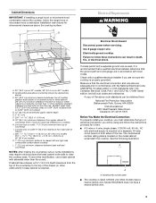
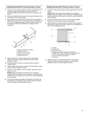
...) in base cabinet is covered by dashed box above) C. 30" (76.2 cm) minimum clearance between back wall and countertop NOTES: After making the countertop cutout, some installations may require notching down the base cabinet side walls to follow the range hood or microwave hood combination installation instructions for it is properly grounded. Most models have a neutral (white) wire. 3 Check with the National Electrical Code, ANSI/NFPA 70-latest edition or CSA Standards C22.1-94, Canadian Electrical Code, Part...
...) in base cabinet is covered by dashed box above) C. 30" (76.2 cm) minimum clearance between back wall and countertop NOTES: After making the countertop cutout, some installations may require notching down the base cabinet side walls to follow the range hood or microwave hood combination installation instructions for it is properly grounded. Most models have a neutral (white) wire. 3 Check with the National Electrical Code, ANSI/NFPA 70-latest edition or CSA Standards C22.1-94, Canadian Electrical Code, Part...
Installation Instructions
Page 4
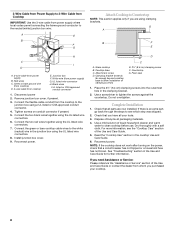
... of the power supply cable (at the cooktop and at cooktop base ends. 30" (76.2 cm) traditional knob models B C A B C A. Complete the following steps for installing clamping brackets at the junction box). Attachment screw C. Remove foam strip roll from the fuse box or circuit breaker box should not be connected directly to do so can be provided at the cooktop. ■ If the house has aluminum wiring, follow the procedure below: 1. Using 2 or more...
... of the power supply cable (at the cooktop and at cooktop base ends. 30" (76.2 cm) traditional knob models B C A B C A. Complete the following steps for installing clamping brackets at the junction box). Attachment screw C. Remove foam strip roll from the fuse box or circuit breaker box should not be connected directly to do so can be provided at the cooktop. ■ If the house has aluminum wiring, follow the procedure below: 1. Using 2 or more...
Installation Instructions
Page 5
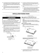
... a covered surface using the bracket mounting holes selected in "Attach Cooktop to the edge of the cooktop base. 3. If repositioning is placed in cutout. Select bracket mounting holes that will allow the bracket to avoid scratching the countertop. 8. Using 2 or more people, place cooktop right side up from the cooktop for the bracket locations from the packaging. Countertop 4. Securely tighten screws. 5 Remove the attachment screws for the installation of clamping screw installation. Using...
... a covered surface using the bracket mounting holes selected in "Attach Cooktop to the edge of the cooktop base. 3. If repositioning is placed in cutout. Select bracket mounting holes that will allow the bracket to avoid scratching the countertop. 8. Using 2 or more people, place cooktop right side up from the cooktop for the bracket locations from the packaging. Countertop 4. Securely tighten screws. 5 Remove the attachment screws for the installation of clamping screw installation. Using...
Installation Instructions
Page 6
... circuit breaker box 3-Wire Cable from Power Supply to 4-Wire Cable from power supply where local codes do not permit connecting the frame-ground conductor to the junction box using a UL listed or CSA approved connector for ½" (1.3 cm) conduit. 4. Connect the two white wires together using the UL listed wire connectors. 7. Install junction box cover. 10. White wires G. Reconnect power. 3-wire direct 3¹⁄₂" (8.9 cm) A fused disconnect or circuit breaker box 3-Wire Cable from Power Supply to 3-Wire Cable from power supply B. Electrically...
... circuit breaker box 3-Wire Cable from Power Supply to 4-Wire Cable from power supply where local codes do not permit connecting the frame-ground conductor to the junction box using a UL listed or CSA approved connector for ½" (1.3 cm) conduit. 4. Connect the two white wires together using the UL listed wire connectors. 7. Install junction box cover. 10. White wires G. Reconnect power. 3-wire direct 3¹⁄₂" (8.9 cm) A fused disconnect or circuit breaker box 3-Wire Cable from Power Supply to 3-Wire Cable from power supply B. Electrically...
Installation Instructions
Page 8
... a circuit breaker has not tripped or a household fuse has not blown. Glass cooktop B. Foam seal 1. Complete Installation 1. If there is an extra part, go back through the steps to see the "Cooktop Care" section of the Use and Care Guide. 5. UL listed wire connector H. Connect the two red wires together using the UL listed wire connectors. 6. Clamping bracket (extends far enough beyond cooktop base to allow installation of liquid household cleaner and warm water to clean cooktop before use. Use...
... a circuit breaker has not tripped or a household fuse has not blown. Glass cooktop B. Foam seal 1. Complete Installation 1. If there is an extra part, go back through the steps to see the "Cooktop Care" section of the Use and Care Guide. 5. UL listed wire connector H. Connect the two red wires together using the UL listed wire connectors. 6. Clamping bracket (extends far enough beyond cooktop base to allow installation of liquid household cleaner and warm water to clean cooktop before use. Use...

Warranty
Page 1
... removed, altered or cannot be borne by Whirlpool. 5. Costs associated with the product, Whirlpool Corporation or Whirlpool Canada LP (hereafter "Whirlpool") will need to repair or replace appliance light bulbs, air filters or water filters. If you ever need service, first see the "Troubleshooting" section of repair or replacement under this limited warranty does not apply. Damage resulting from warranty coverage. 3. In Canada, call 1-800-253-1301. The cost of the Use & Care Guide...
... removed, altered or cannot be borne by Whirlpool. 5. Costs associated with the product, Whirlpool Corporation or Whirlpool Canada LP (hereafter "Whirlpool") will need to repair or replace appliance light bulbs, air filters or water filters. If you ever need service, first see the "Troubleshooting" section of repair or replacement under this limited warranty does not apply. Damage resulting from warranty coverage. 3. In Canada, call 1-800-253-1301. The cost of the Use & Care Guide...
Dimension Guide
Page 1
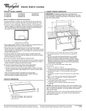
The model/serial number rating plate is required on a separate, 40-amp circuit fused on 36" (91.4 cm) models K. 1" (2.5 cm) minimum distance to nearest left and right side combustible surface above cooktop L. 1" (2.5 cm) minimum clearance between back wall and countertop NOTES: After making the countertop cutout, some installations may require notching down the base cabinet side walls to clear the cooktop base. Model/serial number plate q The cooktop is covered by dashed box above the cooktop surface. Use the length of the drawer (or other...
The model/serial number rating plate is required on a separate, 40-amp circuit fused on 36" (91.4 cm) models K. 1" (2.5 cm) minimum distance to nearest left and right side combustible surface above cooktop L. 1" (2.5 cm) minimum clearance between back wall and countertop NOTES: After making the countertop cutout, some installations may require notching down the base cabinet side walls to clear the cooktop base. Model/serial number plate q The cooktop is covered by dashed box above the cooktop surface. Use the length of the drawer (or other...


