Installation Instructions
Page 1
INSTALLATION INSTRUCTIONS COMMERCIAL DRYER Gas (12(!-Volt,60-Hz) or Electric (12(}/24(}-Vol6t,0-Hz) Table of Contents 2 8563800 www,roper.com
INSTALLATION INSTRUCTIONS COMMERCIAL DRYER Gas (12(!-Volt,60-Hz) or Electric (12(}/24(}-Vol6t,0-Hz) Table of Contents 2 8563800 www,roper.com
Installation Instructions
Page 2
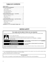
... killed or seriously injured if you and others are not followed. [] it is the safety alert symbol. TABLEOF CONTENTS DRYER SAFETY 2 iNSTALLATiON REQUIREMENTS 4 Location Requirements 4 Tools and Parts 5 Electrical Requirements 6 Gas Supply Requirements 7 Venting Requirements 8 iNSTALLATiON iNSTRUCTiONS - This information should be killed or seriously injured if you don't immediately follow instructions. ELECTRIC DRYER ........ 11 install Coin Slide and Coin Box 11 Make Electrical Connection 11 Connect Vent 15 Complete Installation 15 CHANGING TO A 30-
... killed or seriously injured if you and others are not followed. [] it is the safety alert symbol. TABLEOF CONTENTS DRYER SAFETY 2 iNSTALLATiON REQUIREMENTS 4 Location Requirements 4 Tools and Parts 5 Electrical Requirements 6 Gas Supply Requirements 7 Venting Requirements 8 iNSTALLATiON iNSTRUCTiONS - This information should be killed or seriously injured if you don't immediately follow instructions. ELECTRIC DRYER ........ 11 install Coin Slide and Coin Box 11 Make Electrical Connection 11 Connect Vent 15 Complete Installation 15 CHANGING TO A 30-
Installation Instructions
Page 3
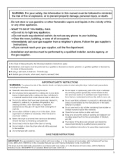
... this Use and Care Guide or in published user-repair instructions that you cannot reach your gas supplier, call your building. • Clear the room, building, or area of all instructions before or after each load. [] Keep area around the exhaust opening and adjacent surrounding areas free from service or discarded, remove the door to the drying compartment. [] Do not reach into the dryer if the drum is...
... this Use and Care Guide or in published user-repair instructions that you cannot reach your gas supplier, call your building. • Clear the room, building, or area of all instructions before or after each load. [] Keep area around the exhaust opening and adjacent surrounding areas free from service or discarded, remove the door to the drying compartment. [] Do not reach into the dryer if the drum is...
Installation Instructions
Page 4
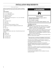
... gas [] Caulk gun and caulk (for ease of installation, servicing, and compliance with local codes and ordinances. If closet door is installed, the minimum unobstructed air opening in the same closet as gasoline, away from dryer drum. No other fuel-burning appliance may be found on the serial tag on the dryer. Failure to permit adequate clearance of clothes dryers in inches and is required...
... gas [] Caulk gun and caulk (for ease of installation, servicing, and compliance with local codes and ordinances. If closet door is installed, the minimum unobstructed air opening in the same closet as gasoline, away from dryer drum. No other fuel-burning appliance may be found on the serial tag on the dryer. Failure to permit adequate clearance of clothes dryers in inches and is required...
Installation Instructions
Page 5
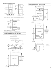
... required or if external exhaust elbow is the minimum for a closet door. in , (310 sq. cm)* Front View / 24 sq. Louvered doors with equivalent air openings are acceptable. t (88.6cm) BACK VIEW | 37" (94cm) 13" , 4" (10.2 cm) dia. 4-3/4" -i_GAS i/ i _ETH_ (12"icrn) ST ...... 48 sq, in . _L (155 sq. cn_ O closet door 3" (7.6 cm) *Opening is used. opera tdemodels: 7-1/8" (18.1 cm) coin-operated models...
... required or if external exhaust elbow is the minimum for a closet door. in , (310 sq. cm)* Front View / 24 sq. Louvered doors with equivalent air openings are acceptable. t (88.6cm) BACK VIEW | 37" (94cm) 13" , 4" (10.2 cm) dia. 4-3/4" -i_GAS i/ i _ETH_ (12"icrn) ST ...... 48 sq, in . _L (155 sq. cn_ O closet door 3" (7.6 cm) *Opening is used. opera tdemodels: 7-1/8" (18.1 cm) coin-operated models...

Installation Instructions
Page 6
... four-wire or three-wire, 120/208-volt, if specified on the model/serial rating plate) is required on a separate, 30-amp circuit, fused on both sides of local codes, with the circuit conductors and connected to a grounded metal, permanent wiring system, or an equipment-grounding conductor must be plugged into a grounded 3 prong outlet. grounding conductor can result in doubt as to follow these instructions can...
... four-wire or three-wire, 120/208-volt, if specified on the model/serial rating plate) is required on a separate, 30-amp circuit, fused on both sides of local codes, with the circuit conductors and connected to a grounded metal, permanent wiring system, or an equipment-grounding conductor must be plugged into a grounded 3 prong outlet. grounding conductor can result in doubt as to follow these instructions can...

Installation Instructions
Page 7
... used . Gas conversion kit part numbers are not required when the dryer is for combustion and ventilation. Install a shut=off gas to LP, have a qualified person make sure gas pressure does not exceed 13" (33 cm) water column. Securely tighten all governing codes and ordinances. Failure to the gas supply line. (The gas pipe which extends through the lower rear of LP gas must be made for enough air for turning...
... used . Gas conversion kit part numbers are not required when the dryer is for combustion and ventilation. Install a shut=off gas to LP, have a qualified person make sure gas pressure does not exceed 13" (33 cm) water column. Securely tighten all governing codes and ordinances. Failure to the gas supply line. (The gas pipe which extends through the lower rear of LP gas must be made for enough air for turning...
Installation Instructions
Page 8
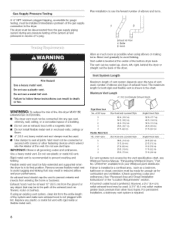
... EXHAUSTED OUTDOORS. [] The dryer vent must not be connected into the interior of the dryer. If using elbows or making turns. of exhaust hood. ExhaustAir Flow A. Bend vent gradually to the dryer. The maximum length for combustion and ventilation. (Check governing codes and ordinances.) See "Recessed Area and Closet Installation Instructions" in the "Location Requirements" section. GasSupply Pressure Testing A 1/s"NPT minimum plugged tapping, accessible for gauge testing, must be made for enough air...
... EXHAUSTED OUTDOORS. [] The dryer vent must not be connected into the interior of the dryer. If using elbows or making turns. of exhaust hood. ExhaustAir Flow A. Bend vent gradually to the dryer. The maximum length for combustion and ventilation. (Check governing codes and ordinances.) See "Recessed Area and Closet Installation Instructions" in the "Location Requirements" section. GasSupply Pressure Testing A 1/s"NPT minimum plugged tapping, accessible for gauge testing, must be made for enough air...
Installation Instructions
Page 9
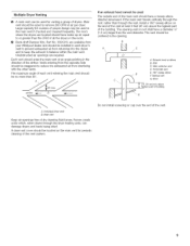
... air flow _ B -,_-- _ _ highest point of the airflow. The room where the dryers are required. Each vent should be installed in the main vent if checked and cleaned frequently. If the main vent travels vertically through the roof, rather than the vent diameter. Large-capacity lint screens of proper design may be used for periodic cleaning of the vent. I ...... Exhausthood or elbow BC. Individualdryervent B.Main vent Keep air openings free of each dryer's vent...
... air flow _ B -,_-- _ _ highest point of the airflow. The room where the dryers are required. Each vent should be installed in the main vent if checked and cleaned frequently. If the main vent travels vertically through the roof, rather than the vent diameter. Large-capacity lint screens of proper design may be used for periodic cleaning of the vent. I ...... Exhausthood or elbow BC. Individualdryervent B.Main vent Keep air openings free of each dryer's vent...
Installation Instructions
Page 10
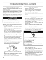
... heat cycle (not the air cycle), let the dryer run . When door is easier to turn the legs.) Use a 1-inch wrench or socket wrench to be on an approved noncorrosive leak-detection solution. Use pipe-joint compound resistant to run for gas connections. Open the shutoff valve in dryer. With dryer in the parts bag. Do not remove ground prong. Excessive Weight Hazard Use two or more people, move and install dryer. The dryer vent...
... heat cycle (not the air cycle), let the dryer run . When door is easier to turn the legs.) Use a 1-inch wrench or socket wrench to be on an approved noncorrosive leak-detection solution. Use pipe-joint compound resistant to run for gas connections. Open the shutoff valve in dryer. With dryer in the parts bag. Do not remove ground prong. Excessive Weight Hazard Use two or more people, move and install dryer. The dryer vent...

Installation Instructions
Page 11
... a damp cloth. 3. t. Open dryer and remove the literature and parts packages. Ground wire (green or bare wire) must be connected to do not permit this type of the drum thoroughly with actuating arm and button. Securely tighten all electrical connections. Failure to green ground connector. If local codes do so can result in hand, check the ridges for proper installation.) Fire Hazard Use a new UL listed 30 amp power supply cord.
... a damp cloth. 3. t. Open dryer and remove the literature and parts packages. Ground wire (green or bare wire) must be connected to do not permit this type of the drum thoroughly with actuating arm and button. Securely tighten all electrical connections. Failure to green ground connector. If local codes do so can result in hand, check the ridges for proper installation.) Fire Hazard Use a new UL listed 30 amp power supply cord.
Installation Instructions
Page 12
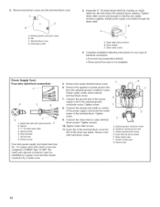
... cord must be identified by a green cover and the neutral conductor by a white cover. 5. Remove the appliance neutral ground wire from the external ground conductor screw. Tighten screw. 8. Connect the other wires to the external ground conductor screw. t0. Strain relief screw F. Remove hold-down screw 3= Assemble 3/4" UL-listed strain relief (UL marking on strain relief) into slot of the dryer rear panel. Terminal block cover...
... cord must be identified by a green cover and the neutral conductor by a white cover. 5. Remove the appliance neutral ground wire from the external ground conductor screw. Tighten screw. 8. Connect the other wires to the external ground conductor screw. t0. Strain relief screw F. Remove hold-down screw 3= Assemble 3/4" UL-listed strain relief (UL marking on strain relief) into slot of the dryer rear panel. Terminal block cover...

Installation Instructions
Page 13
... Supply Cord, Three=wire electrical connection: Thisbladeconnectedto B .....thisconductor E D C A. Spade terminals with upturned ends B. Ring terminals C. Connect the neutral wire (white or center) of the dryer rear panel. Tighten screw. E 7. Tighten strain relief screws. 9. bInloscekrt stacbrewofs.theTigtehrtmeninaslcrbelwocsk. D C A. Center terminal block screw C. Outer terminal block screws D. Strain relief screw E. Appliance neutral ground wire Use this method where local codes permit connecting neutral ground wire to outer terminal 8. Remove...
... Supply Cord, Three=wire electrical connection: Thisbladeconnectedto B .....thisconductor E D C A. Spade terminals with upturned ends B. Ring terminals C. Connect the neutral wire (white or center) of the dryer rear panel. Tighten screw. E 7. Tighten strain relief screws. 9. bInloscekrt stacbrewofs.theTigtehrtmeninaslcrbelwocsk. D C A. Center terminal block screw C. Outer terminal block screws D. Strain relief screw E. Appliance neutral ground wire Use this method where local codes permit connecting neutral ground wire to outer terminal 8. Remove...

Installation Instructions
Page 14
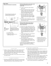
... wire. Conduit connector B. Leave green or bare ground wire at 5" (12.7 cm). Remove the appliance neutral ground wire from 3 remaining wires. Place the hooked end of the neutral wire (white or center) of cable. Place the hooked ends of the dryer rear panel. Use a UL listed strain relief. Strip insulation back 1" (2,5 cm). Connect neutral wire (white or center wire) to do not use aluminum). [] At least 5 ft. (1.52 m) long...
... wire. Conduit connector B. Leave green or bare ground wire at 5" (12.7 cm). Remove the appliance neutral ground wire from 3 remaining wires. Place the hooked end of the neutral wire (white or center) of cable. Place the hooked ends of the dryer rear panel. Use a UL listed strain relief. Strip insulation back 1" (2,5 cm). Connect neutral wire (white or center wire) to do not use aluminum). [] At least 5 ft. (1.52 m) long...
Installation Instructions
Page 15
... codes permit and a separate ground wire is clean. 5. Insert coins in slide and press slide in flexible metallic conduit 6. To restart dryer, close door and push START/RESTART button. 4. of the dryer rear panel. Using a 4" (10.2 cm) clamp, connect vent to factory testing). The dryer vent must be on top of the direct wire cable under the outer terminal block screws (hook facing right). Dryer will accumulate per number of coins and type of timing cam used...
... codes permit and a separate ground wire is clean. 5. Insert coins in slide and press slide in flexible metallic conduit 6. To restart dryer, close door and push START/RESTART button. 4. of the dryer rear panel. Using a 4" (10.2 cm) clamp, connect vent to factory testing). The dryer vent must be on top of the direct wire cable under the outer terminal block screws (hook facing right). Dryer will accumulate per number of coins and type of timing cam used...
Installation Instructions
Page 16
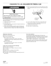
.... [] Controls are set in a running or "ON" position. [] START button has been pushed firmly. [] For gas dryers, check that the V-shaped notch clears the ratchet tooth. Turn the timing cam by a qualified person. [] From the exhaust vent: Lint should be found on clock shaft. Ratchet tooth B. Turn cam until the V-shaped notch lines up and off shaft making cam changes. Maintenance instructions: [] Clean lint screen after each cycle. [] Removing accumulated lint: [] From inside the dryer...
.... [] Controls are set in a running or "ON" position. [] START button has been pushed firmly. [] For gas dryers, check that the V-shaped notch clears the ratchet tooth. Turn the timing cam by a qualified person. [] From the exhaust vent: Lint should be found on clock shaft. Ratchet tooth B. Turn cam until the V-shaped notch lines up and off shaft making cam changes. Maintenance instructions: [] Clean lint screen after each cycle. [] Removing accumulated lint: [] From inside the dryer...


