Installation Instructions
Page 1
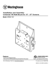
ISSUED: 01-17-06 SHEET #: 202-9091-1 Max UL Load Capacity: 80 lb (36.3 kg) For customer care call 1-866-287-5555. Installation and Assembly: Universal Tilt Wall Mount for 15" - 37" Screens Model: MT80A TILT Features: • Fits 15" to 37" flat panel screens • One-touch tilt for effortless positioning and adjustment of the screen Visit the Westinghouse Web Site at www.westinghousedigital.com This product is intended for use with UL Listed products and must be installed by a R qualified professional installer.
ISSUED: 01-17-06 SHEET #: 202-9091-1 Max UL Load Capacity: 80 lb (36.3 kg) For customer care call 1-866-287-5555. Installation and Assembly: Universal Tilt Wall Mount for 15" - 37" Screens Model: MT80A TILT Features: • Fits 15" to 37" flat panel screens • One-touch tilt for effortless positioning and adjustment of the screen Visit the Westinghouse Web Site at www.westinghousedigital.com This product is intended for use with UL Listed products and must be installed by a R qualified professional installer.

Installation Instructions
Page 2
... sure that mounting screws are anchored into the center of 8 ISSUED: 01-17-06 SHEET #: 202-9091-1 Overtightening can damage the items, greatly reducing their holding power. Use of the equipment and all attached hardware and compo- Note: Read entire instruction sheet before you have read and understood the instructions and warnings contained in this Installation Sheet. nents. •...
... sure that mounting screws are anchored into the center of 8 ISSUED: 01-17-06 SHEET #: 202-9091-1 Overtightening can damage the items, greatly reducing their holding power. Use of the equipment and all attached hardware and compo- Note: Read entire instruction sheet before you have read and understood the instructions and warnings contained in this Installation Sheet. nents. •...
Installation Instructions
Page 3
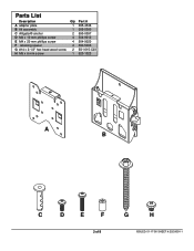
Parts List Description A adapter plate B tilt assembly C Alligator® anchor D M4 x 10 mm phillips screw E M4 x 20 mm phillips screw F retaining spacer G #14 x 2-1/2" hex head wood screw H M5 x 6 mm screw Qty Part # 1 095-4346 1 095-0360 2 590-0097 4 504-9012 4 504-9020 4 590-5005 2 5S1-015-C03 1 520-1023 A B C D E F 3 of 8 G H ISSUED: 01-17-06 SHEET #: 202-9091-1
Parts List Description A adapter plate B tilt assembly C Alligator® anchor D M4 x 10 mm phillips screw E M4 x 20 mm phillips screw F retaining spacer G #14 x 2-1/2" hex head wood screw H M5 x 6 mm screw Qty Part # 1 095-4346 1 095-0360 2 590-0097 4 504-9012 4 504-9020 4 590-5005 2 5S1-015-C03 1 520-1023 A B C D E F 3 of 8 G H ISSUED: 01-17-06 SHEET #: 202-9091-1
Installation Instructions
Page 4
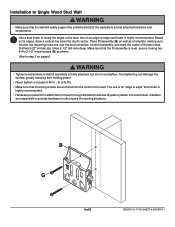
... screws so that the wall will safely support the combined load of the equipment and all attached hardware and components. 1 Use a stud finder to locate the edges of mounting situations. Installation to Single Wood Stud Wall WARNING • Make sure that tilt ...assembly is firmly attached, but do not overtighten. Level tilt assembly, and mark the center of 8 ISSUED: 01-17-06 SHEET #: 202-9091-1 Overtightening can damage the screws...
... screws so that the wall will safely support the combined load of the equipment and all attached hardware and components. 1 Use a stud finder to locate the edges of mounting situations. Installation to Single Wood Stud Wall WARNING • Make sure that tilt ...assembly is firmly attached, but do not overtighten. Level tilt assembly, and mark the center of 8 ISSUED: 01-17-06 SHEET #: 202-9091-1 Overtightening can damage the screws...
Installation Instructions
Page 5
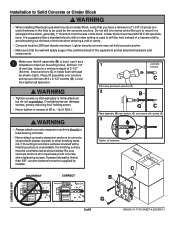
... and secure with plaster, drywall, or other finishing material. Do not drill into mortar joints! Cinder block must be supplied by installer. Overtightening can damage screws, greatly reducing their holding power. • Never tighten in . • lb (9 N.M.). Installation to Solid Concrete or Cinder Block WARNING • When installing Westinghouse wall mounts on slow setting is used for the concrete anchors...
... and secure with plaster, drywall, or other finishing material. Do not drill into mortar joints! Cinder block must be supplied by installer. Overtightening can damage screws, greatly reducing their holding power. • Never tighten in . • lb (9 N.M.). Installation to Solid Concrete or Cinder Block WARNING • When installing Westinghouse wall mounts on slow setting is used for the concrete anchors...
Installation Instructions
Page 6
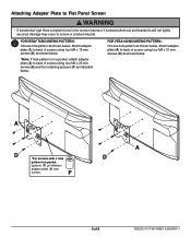
... fail. 2 FOR VESA® 75 MOUNTING PATTERN: Choose hole pattern as shown below . F A D 6 of 8 ISSUED: 01-17-06 SHEET #: 202-9091-1 Attach adapter plate (A) to back of screen using four M4 x 10 mm screws (D) as shown below . A D *For screens with a hole pattern in a pocket,... attach adapter plate (A) to back of screen using four M4 x 20 mm screws (E) and four retaining spacers (F) as shown below . Attaching Adapter Plate to Flat Panel Screen WARNING • If screws don't get three complete turns in the screen inserts or if screws bottom out and bracket...
... fail. 2 FOR VESA® 75 MOUNTING PATTERN: Choose hole pattern as shown below . F A D 6 of 8 ISSUED: 01-17-06 SHEET #: 202-9091-1 Attach adapter plate (A) to back of screen using four M4 x 10 mm screws (D) as shown below . A D *For screens with a hole pattern in a pocket,... attach adapter plate (A) to back of screen using four M4 x 20 mm screws (E) and four retaining spacers (F) as shown below . Attaching Adapter Plate to Flat Panel Screen WARNING • If screws don't get three complete turns in the screen inserts or if screws bottom out and bracket...
Installation Instructions
Page 7
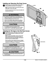
...size and weight. Note: For security models, use security driver (I) to adjust tilt as stated in step 3. Use additional man power or mechanical lifting equipment to safely handle placement of the screen. • Failure to lock adapter plate (A) with screw (H) can cause damage to pinch fingers when pushing screen from mount, loosen screw (H) and lift screen off mount if hit accidentally. Installing...8226; Do not lift more weight than you can be adjusted to tilt assemby. CAUTION • Do not tighten screws with excessive force. Adjusting the Tilt Angle of the Flat Panel ...
...size and weight. Note: For security models, use security driver (I) to adjust tilt as stated in step 3. Use additional man power or mechanical lifting equipment to safely handle placement of the screen. • Failure to lock adapter plate (A) with screw (H) can cause damage to pinch fingers when pushing screen from mount, loosen screw (H) and lift screen off mount if hit accidentally. Installing...8226; Do not lift more weight than you can be adjusted to tilt assemby. CAUTION • Do not tighten screws with excessive force. Adjusting the Tilt Angle of the Flat Panel ...
Installation Instructions
Page 8
..., or (d) misuse or accident, in material and workmanship, under license. A sales receipt, invoice, or other instructions regarding return and replacement or repair of purchase by Westinghouse Digital Electronics, (b) the failure to utilize proper packing when returning the product, (c) improper installation or the failure to the end-user, whichever occurs last. ANY IMPLIED WARRANTY OF MERCHANTABILITY OR FITNESS...
..., or (d) misuse or accident, in material and workmanship, under license. A sales receipt, invoice, or other instructions regarding return and replacement or repair of purchase by Westinghouse Digital Electronics, (b) the failure to utilize proper packing when returning the product, (c) improper installation or the failure to the end-user, whichever occurs last. ANY IMPLIED WARRANTY OF MERCHANTABILITY OR FITNESS...