
English Manual
Page 1
... Read all precautions and instructions in the space above for future reference. USERʼS MANUAL IMPORTANT: Please register this product (see the limited warranty on the back cover of this manual) before using this equipment. CALL TOLL-FREE: 1-866-699-3756 Mon.-Fri., 6 a.m.-6 p.m. Keep this manual before contacting Customer Care. Serial Number Decal QUESTIONS? If you have questions, or if parts are damaged or...
... Read all precautions and instructions in the space above for future reference. USERʼS MANUAL IMPORTANT: Please register this product (see the limited warranty on the back cover of this manual) before using this equipment. CALL TOLL-FREE: 1-866-699-3756 Mon.-Fri., 6 a.m.-6 p.m. Keep this manual before contacting Customer Care. Serial Number Decal QUESTIONS? If you have questions, or if parts are damaged or...
English Manual
Page 2
... of ICON IP, Inc. 2 WESLO is missing or illegible, see the front cover of the warning decal(s). TABLE OF CONTENTS WARNING DECAL PLACEMENT 2 IMPORTANT PRECAUTIONS 3 BEFORE YOU BEGIN 4 ASSEMBLY 5 HOW TO USE THE EXERCISE CYCLE 11 MAINTENANCE AND TROUBLESHOOTING 15 EXERCISE GUIDELINES 16 PART LIST 18 EXPLODED DRAWING 19 ORDERING REPLACEMENT PARTS Back Cover LIMITED WARRANTY Back Cover WARNING DECAL PLACEMENT This drawing shows the location(s) of this manual...
... of ICON IP, Inc. 2 WESLO is missing or illegible, see the front cover of the warning decal(s). TABLE OF CONTENTS WARNING DECAL PLACEMENT 2 IMPORTANT PRECAUTIONS 3 BEFORE YOU BEGIN 4 ASSEMBLY 5 HOW TO USE THE EXERCISE CYCLE 11 MAINTENANCE AND TROUBLESHOOTING 15 EXERCISE GUIDELINES 16 PART LIST 18 EXPLODED DRAWING 19 ORDERING REPLACEMENT PARTS Back Cover LIMITED WARRANTY Back Cover WARNING DECAL PLACEMENT This drawing shows the location(s) of this manual...
English Manual
Page 3
... general. 9. When adjusting the seat, insert the seat pin into one of heart rate readings. do not wear loose clothes that there is intended only as described in this manual. 3 Keep children under the seat post. 11. Do not use your exercise cycle; The pulse sensor is at all warnings on your exercise cycle before using your exercise cycle in a commercial, rental, or institutional setting. 8. Always...
... general. 9. When adjusting the seat, insert the seat pin into one of heart rate readings. do not wear loose clothes that there is intended only as described in this manual. 3 Keep children under the seat post. 11. Do not use your exercise cycle; The pulse sensor is at all warnings on your exercise cycle before using your exercise cycle in a commercial, rental, or institutional setting. 8. Always...
English Manual
Page 4
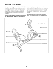
... serial number before you use the exercise cycle. If you for increasing cardiovascular fitness, building endurance, and toning the body. BEFORE YOU BEGIN Thank you have questions after reading this manual, please see the front cover of this manual. To help us . The PURSUIT G 3.8 exercise cycle provides a selection of features designed to make your benefit, read this manual. Handlebar Backrest Seat Seat Frame Console Thumb Pulse Sensor Resistance Knob Pedal/Strap Adjustment Knob Seat...
... serial number before you use the exercise cycle. If you for increasing cardiovascular fitness, building endurance, and toning the body. BEFORE YOU BEGIN Thank you have questions after reading this manual, please see the front cover of this manual. To help us . The PURSUIT G 3.8 exercise cycle provides a selection of features designed to make your benefit, read this manual. Handlebar Backrest Seat Seat Frame Console Thumb Pulse Sensor Resistance Knob Pedal/Strap Adjustment Knob Seat...
English Manual
Page 5
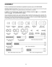
... Screw (66)-2 Screw (47)-4 M6 x 30mm Button Bolt (64)-4 M6 x 35mm Button Screw (61)-8 M8 x 65mm Button Bolt (36)-2 M8 x 20mm Button Screw (34)-3 M10 x 65mm Button Screw (33)-2 M8 x 125mm Bolt (62)-2 M10 x 75mm Carriage Bolt (30)-2 5 ASSEMBLY To hire an authorized service technician to identify the small parts used in a cleared area and remove the packing materials. Place all parts of this manual. The number in parentheses below to assemble the exercise...
... Screw (66)-2 Screw (47)-4 M6 x 30mm Button Bolt (64)-4 M6 x 35mm Button Screw (61)-8 M8 x 65mm Button Bolt (36)-2 M8 x 20mm Button Screw (34)-3 M10 x 65mm Button Screw (33)-2 M8 x 125mm Bolt (62)-2 M10 x 75mm Carriage Bolt (30)-2 5 ASSEMBLY To hire an authorized service technician to identify the small parts used in a cleared area and remove the packing materials. Place all parts of this manual. The number in parentheses below to assemble the exercise...
English Manual
Page 6
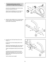
... two M4 Washers (70). Carefully tip the exercise cycle onto its side. Tip the exercise cycle upright. 3 66 57 70 9 1 66 56 5 70 29 6 Tighten the Adjustment Knob (9) into the Frame (1). 1. Attach the Front Stabilizer (2) to the Frame (1) with two M10 x 65mm Button Screws (33). 1 33 2 Large Holes 1 2. To make assembly easier, read the information on page 5 before you begin. Insert...
... two M4 Washers (70). Carefully tip the exercise cycle onto its side. Tip the exercise cycle upright. 3 66 57 70 9 1 66 56 5 70 29 6 Tighten the Adjustment Knob (9) into the Frame (1). 1. Attach the Front Stabilizer (2) to the Frame (1) with two M10 x 65mm Button Screws (33). 1 33 2 Large Holes 1 2. To make assembly easier, read the information on page 5 before you begin. Insert...

English Manual
Page 7
... Button Bolts (64), two M6 Curved Washers (69), and two M6 Locknuts (63). Tighten the two M8 Locknuts (10). 60 15 14 68 61 68 68 61 7 Attach the Backrest (60) to the Seat Frame (5) with four M6 x 35mm Button Screws 6 (61) and four M6 Washers (68). 4. See step 4. Attach the Left and Right Seat Brackets (14, 15) 4 to the Seat...
... Button Bolts (64), two M6 Curved Washers (69), and two M6 Locknuts (63). Tighten the two M8 Locknuts (10). 60 15 14 68 61 68 68 61 7 Attach the Backrest (60) to the Seat Frame (5) with four M6 x 35mm Button Screws 6 (61) and four M6 Washers (68). 4. See step 4. Attach the Left and Right Seat Brackets (14, 15) 4 to the Seat...

English Manual
Page 8
... 8. Connect the Resistance Cable (19) to the Lower Cable (45) in the position shown, connect the Extension Wire (52) to the Reed Wire (43). Pull upward on the metal bracket on the upper end of the metal bracket as shown. • See drawing B. Tip: Avoid pinching the wires. Attach the Upright (13) to the Seat Brackets (14, 15) with three M8 x 20mm Button Screws (34...
... 8. Connect the Resistance Cable (19) to the Lower Cable (45) in the position shown, connect the Extension Wire (52) to the Reed Wire (43). Pull upward on the metal bracket on the upper end of the metal bracket as shown. • See drawing B. Tip: Avoid pinching the wires. Attach the Upright (13) to the Seat Brackets (14, 15) with three M8 x 20mm Button Screws (34...

English Manual
Page 9
... Upright (13), connect the console wire to the Upright (13) with four M4 x 15mm Self-tapping Screws (47). 11 16 Avoid pinching the wires 52 47 13 Console Wire 9 9. Remove the battery cover, insert the batteries into the Upright (13). mended. Insert the wires downward into the battery compartment, and reattach the battery cover. alkaline batteries are recom- Otherwise, you may damage the console displays or other electronic components. Screw 16 Battery Cover Batteries 11. Attach...
... Upright (13), connect the console wire to the Upright (13) with four M4 x 15mm Self-tapping Screws (47). 11 16 Avoid pinching the wires 52 47 13 Console Wire 9 9. Remove the battery cover, insert the batteries into the Upright (13). mended. Insert the wires downward into the battery compartment, and reattach the battery cover. alkaline batteries are recom- Otherwise, you may damage the console displays or other electronic components. Screw 16 Battery Cover Batteries 11. Attach...
English Manual
Page 10
..., and press the end of the Crank (21). Adjust the strap on the Left Pedal (24) to protect the floor. 10 12. Tighten the Right Pedal (not shown) clockwise into the left over. IMPORTANT: Tighten both pedals as firmly as possible. For best performance, keep the pedals tightened. Make sure that all parts are properly tightened before you use the exercise cycle. After assembly is marked...
..., and press the end of the Crank (21). Adjust the strap on the Left Pedal (24) to protect the floor. 10 12. Tighten the Right Pedal (not shown) clockwise into the left over. IMPORTANT: Tighten both pedals as firmly as possible. For best performance, keep the pedals tightened. Make sure that all parts are properly tightened before you use the exercise cycle. After assembly is marked...

English Manual
Page 11
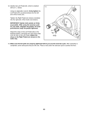
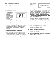
... the adjustment knob. 11 IMPORTANT: Stop turning the knob when turning becomes difficult, or damage may result. As you pedal, there should be a slight bend in your knees when the pedals are in the proper position. To increase the resistance of the pedals, turn the knob counterclockwise. Slide the seat frame forward or backward to decrease the resistance, turn the resistance knob clockwise; HOW TO USE THE EXERCISE CYCLE...
... the adjustment knob. 11 IMPORTANT: Stop turning the knob when turning becomes difficult, or damage may result. As you pedal, there should be a slight bend in your knees when the pedals are in the proper position. To increase the resistance of the pedals, turn the knob counterclockwise. Slide the seat frame forward or backward to decrease the resistance, turn the resistance knob clockwise; HOW TO USE THE EXERCISE CYCLE...
English Manual
Page 12
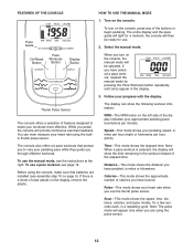
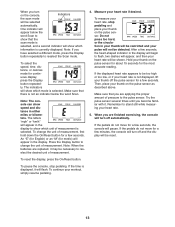
...-This mode shows the speed, time, distance, calories, and pulse modes, for a moment; On/Reset Button Pace Workouts Button Display Button When you are installed (see assembly step 10 on the console, the manual mode will provide continuous exercise feedback. While you have pedaled, in the workout instead of the display indicates your heart rate using the pulse sensor. 12 Speed-This mode shows your progress with the display. If there is selected, the display will appear only when you turn...
...-This mode shows the speed, time, distance, calories, and pulse modes, for a moment; On/Reset Button Pace Workouts Button Display Button When you are installed (see assembly step 10 on the console, the manual mode will provide continuous exercise feedback. While you have pedaled, in the workout instead of the display indicates your heart rate using the pulse sensor. 12 Speed-This mode shows your progress with the display. If there is selected, the display will appear only when you turn...
English Manual
Page 13
... mode, press the Display button repeatedly to change the unit of measurement. To continue your thumb off the pulse sensor for continuous display, press the Display button repeatedly. Note: When the batteries are finished exercising, the console will turn off automatically. Hold your thumb on the pulse sensor as described above. If the time is not displayed, lift your workout, simply resume pedaling. 13 To select the speed, time, distance, or calories mode...
... mode, press the Display button repeatedly to change the unit of measurement. To continue your thumb off the pulse sensor for continuous display, press the Display button repeatedly. Note: When the batteries are finished exercising, the console will turn off automatically. Hold your thumb on the pulse sensor as described above. If the time is not displayed, lift your workout, simply resume pedaling. 13 To select the speed, time, distance, or calories mode...
English Manual
Page 14
... your heart rate if desired. See step 3 on page 12. 2. See step 5 on the console. Turn on page 13. 14 Begin pedaling to keep your progress with the display. Make sure to alert you. The display can show the time remaining in the display. If you stop pedaling for a few seconds to pedal at a pace that is displayed. During the workout, the pace guide will show...
... your heart rate if desired. See step 3 on page 12. 2. See step 5 on the console. Turn on page 13. 14 Begin pedaling to keep your progress with the display. Make sure to alert you. The display can show the time remaining in the display. If you stop pedaling for a few seconds to pedal at a pace that is displayed. During the workout, the pace guide will show...
English Manual
Page 15
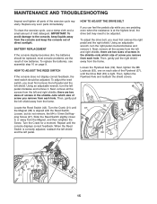
... the exercise cycle regularly. BATTERY REPLACEMENT If the console display becomes dim, the batteries should be replaced; To adjust the reed switch, you must first remove the right pedal and the right shield. there are two sizes of screws in the shields-note which size of direct sunlight. Turn the Crank (21) until the console displays correct feedback. Repeat until the Magnet (38) is at the highest level, the drive belt may need...
... the exercise cycle regularly. BATTERY REPLACEMENT If the console display becomes dim, the batteries should be replaced; To adjust the reed switch, you must first remove the right pedal and the right shield. there are two sizes of screws in the shields-note which size of direct sunlight. Turn the Crank (21) until the console displays correct feedback. Repeat until the Magnet (38) is at the highest level, the drive belt may need...
English Manual
Page 16
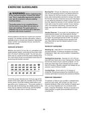
... period of heart rate readings. During the first few months of your exercise until your heart rate is near the highest number in your goal is to strengthen your body begin to five workouts each week, if desired. For maximum fat burning, exercise with pre-existing health problems. The pulse sensor is near the middle number in your training zone. A warm-up to use your cardiovascular...
... period of heart rate readings. During the first few months of your exercise until your heart rate is near the highest number in your goal is to strengthen your body begin to five workouts each week, if desired. For maximum fat burning, exercise with pre-existing health problems. The pulse sensor is near the middle number in your training zone. A warm-up to use your cardiovascular...
English Manual
Page 17
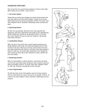
...back and shoulders to your hips. Hamstring Stretch Sit with your knees outward. Repeat 3 times for 15 counts, then relax. Stretches: Hamstrings, lower back and groin. 3. Repeat 3 times. Toe Touch Stretch Stand with the soles of the opposite foot toward the wall. Stretches: Calves,.... Hold for several basic stretches is shown at the right. Calf/Achilles Stretch 3 With one leg extended. SUGGESTED STRETCHES The correct form for 15 counts, then relax. Move slowly as possible. Hold for 15 counts, then relax. Stretches: Hamstrings, back of the achilles...
...back and shoulders to your hips. Hamstring Stretch Sit with your knees outward. Repeat 3 times for 15 counts, then relax. Stretches: Hamstrings, lower back and groin. 3. Repeat 3 times. Toe Touch Stretch Stand with the soles of the opposite foot toward the wall. Stretches: Calves,.... Hold for several basic stretches is shown at the right. Calf/Achilles Stretch 3 With one leg extended. SUGGESTED STRETCHES The correct form for 15 counts, then relax. Move slowly as possible. Hold for 15 counts, then relax. Stretches: Hamstrings, back of the achilles...
English Manual
Page 18
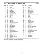
... 1 Right Pedal/Strap 27 1 Resistance Knob 28 2 U-bracket 29 2 M4 x 8mm Screw 30 2 M10 x 75mm Carriage Bolt 31 2 Eyebolt 32 1 M6 Nut 33 2 M10 x 65mm Button Screw 34 3 M8 x 20mm Button Screw 35 1 Drive Belt 36 2 M8 x 65mm Button Bolt 37 1 Flywheel 38 2 Magnet 39 1 Flywheel Axle 40 2 M10 Small Washer 41 5 M4 x 25mm Screw 42 3 M8 Split Washer 43 1 Reed Switch/Wire 44 1 Crank Bearing Set 45 1 Lower Cable 46 2 M8...
... 1 Right Pedal/Strap 27 1 Resistance Knob 28 2 U-bracket 29 2 M4 x 8mm Screw 30 2 M10 x 75mm Carriage Bolt 31 2 Eyebolt 32 1 M6 Nut 33 2 M10 x 65mm Button Screw 34 3 M8 x 20mm Button Screw 35 1 Drive Belt 36 2 M8 x 65mm Button Bolt 37 1 Flywheel 38 2 Magnet 39 1 Flywheel Axle 40 2 M10 Small Washer 41 5 M4 x 25mm Screw 42 3 M8 Split Washer 43 1 Reed Switch/Wire 44 1 Crank Bearing Set 45 1 Lower Cable 46 2 M8...
English Manual
Page 19
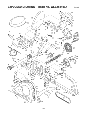
WLEX61408.1 R0709A 59 7 50 60 58 63 54 68 69 12 58 10 69 68 54 61 64 7 50 59 58 54 62 68 61 62 63 54 69 69 64 45 4 33 58 61 61 68 46 10 14 61 55 68 67 61 13 34 42 3 42 34 19 15 68 68 61 52 47 53 3 36 38 16 26 21 27 38 39 25 40 63 4 17 47 2 24 41 42 22 34 47 43 1 10 31 23 28 41 63 47 66 41 18 49 10 9 44 25 40 10 11 66 51 20 32 47 56 71 48 47 57 70 29 6 8 65 31 28 37 5 65 41 41 30 35 8 19 EXPLODED DRAWING-Model No.
WLEX61408.1 R0709A 59 7 50 60 58 63 54 68 69 12 58 10 69 68 54 61 64 7 50 59 58 54 62 68 61 62 63 54 69 69 64 45 4 33 58 61 61 68 46 10 14 61 55 68 67 61 13 34 42 3 42 34 19 15 68 68 61 52 47 53 3 36 38 16 26 21 27 38 39 25 40 63 4 17 47 2 24 41 42 22 34 47 43 1 10 31 23 28 41 63 47 66 41 18 49 10 9 44 25 40 10 11 66 51 20 32 47 56 71 48 47 57 70 29 6 8 65 31 28 37 5 65 41 41 30 35 8 19 EXPLODED DRAWING-Model No.
English Manual
Page 20
... products used for service needed under warranty. To help us : • the model number and serial number of the product (see the front cover of this manual) • the name of the product (see the front cover of this manual) • the key number and description of the replacement part(s) (see the front cover of this product to state. ICONʼs obligation under this manual) LIMITED WARRANTY IMPORTANT: You must be free...
... products used for service needed under warranty. To help us : • the model number and serial number of the product (see the front cover of this manual) • the name of the product (see the front cover of this manual) • the key number and description of the replacement part(s) (see the front cover of this product to state. ICONʼs obligation under this manual) LIMITED WARRANTY IMPORTANT: You must be free...


