
English Manual
Page 4
... 55 40 38 9 41 32 Hole 1 50 3 Assembly requires a phillips screwdriver and an adjustable wrench . Remove the Shipping Insert (54) from the Frame. Press a Pivot Endcap (50) onto each Nylon Locknut until at least two threads on the front of the packing materials until assembly is turned so... the square holes are facing away from the Frame (1) and discard it. Align the Front Stabilizer (5) with the hole in each Handlebar. Make sure that the Front Stabilizer is completed. Attach ...
... 55 40 38 9 41 32 Hole 1 50 3 Assembly requires a phillips screwdriver and an adjustable wrench . Remove the Shipping Insert (54) from the Frame. Press a Pivot Endcap (50) onto each Nylon Locknut until at least two threads on the front of the packing materials until assembly is turned so... the square holes are facing away from the Frame (1) and discard it. Align the Front Stabilizer (5) with the hole in each Handlebar. Make sure that the Front Stabilizer is completed. Attach ...
English Manual
Page 5
...may be left over after assembly is marked with 6 an "R." Next, plug the Reed Switch Wire (28) fully into the Frame. Press the Frame Bushing (4) into the Frame (1). (Note: The Frame Bushing may be pre-assembled.) Next, insert the Seat Post (10) into the socket on the back of the Crank (20...be pre-attached to the Seat. Remove only the Right Pedal Nut (47) and the Pedal Bushing (46) from damage. 5 it slides into the Frame. 6. Repeat this step to the inset drawing. Place a mat under the Seat Post. 4. Refer to attach the Left Pedal (not shown), turning the...
...may be left over after assembly is marked with 6 an "R." Next, plug the Reed Switch Wire (28) fully into the Frame. Press the Frame Bushing (4) into the Frame (1). (Note: The Frame Bushing may be pre-assembled.) Next, insert the Seat Post (10) into the socket on the back of the Crank (20...be pre-attached to the Seat. Remove only the Right Pedal Nut (47) and the Pedal Bushing (46) from damage. 5 it slides into the Frame. 6. Repeat this step to the inset drawing. Place a mat under the Seat Post. 4. Refer to attach the Left Pedal (not shown), turning the...
English Manual
Page 6
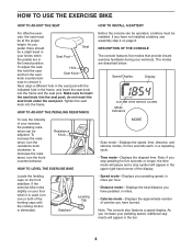
... additional indicators will appear in a repeating cycle. • Time mode-Displays the elapsed time. The modes are in the frame, and insert the seat pin into the frame. Make sure to decrease the resistance, turn the resistance knob clockwise; to insert the seat pin into the seat post; ... exercise feedback during your exercise, the pedaling resistance can be installed. ent hole in the seat post with the hole in the Seat Post Frame lowest position. cise, the seat must be operated, one or both of calories you stop symbol will appear in miles. • Calories ...
... additional indicators will appear in a repeating cycle. • Time mode-Displays the elapsed time. The modes are in the frame, and insert the seat pin into the frame. Make sure to decrease the resistance, turn the resistance knob clockwise; to insert the seat pin into the seat post; ... exercise feedback during your exercise, the pedaling resistance can be installed. ent hole in the seat post with the hole in the Seat Post Frame lowest position. cise, the seat must be operated, one or both of calories you stop symbol will appear in miles. • Calories ...
English Manual
Page 10
Specifications are subject to a non-illustrated part. Qty. Qty. Description Key No. Description 1 1 Frame 2 1 Rear Stabilizer 3 1 Pivot Axle 4 1 Frame Bushing 5 1 Front Stabilizer 6 2 Front Stabilizer Endcap 7 1 Console 8 4 M8 Spring Washer 9 10 M8 Nylon Locknut 10 1 Seat... M8 x 40mm Carriage Bolt 19 1 Crank Bearing Assembly 20 1 Crank 21 1 Left Pedal 22 1 Right Pedal 23 1 Chain 24 1 Resistance Cable/Knob 25 4 7/16" Flat Washer 26 1 Flywheel Axle 27 4 3/8" Axle Nut 28 1 Reed Switch/Wire 29 2 3/8" Axle Nut 30 1 M5 x 15mm ...
Specifications are subject to a non-illustrated part. Qty. Qty. Description Key No. Description 1 1 Frame 2 1 Rear Stabilizer 3 1 Pivot Axle 4 1 Frame Bushing 5 1 Front Stabilizer 6 2 Front Stabilizer Endcap 7 1 Console 8 4 M8 Spring Washer 9 10 M8 Nylon Locknut 10 1 Seat... M8 x 40mm Carriage Bolt 19 1 Crank Bearing Assembly 20 1 Crank 21 1 Left Pedal 22 1 Right Pedal 23 1 Chain 24 1 Resistance Cable/Knob 25 4 7/16" Flat Washer 26 1 Flywheel Axle 27 4 3/8" Axle Nut 28 1 Reed Switch/Wire 29 2 3/8" Axle Nut 30 1 M5 x 15mm ...
English Manual
Page 5
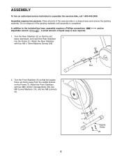
...until assembly is also required. A small amount of the exercise bike in a cleared area and remove the packing materials. Turn the Rear Stabilizer (2) so that the square holes are facing away from the saddle bracket 2 on the Frame (1). Attach the Front Stabilizer with four M6 x 10mm Machine... Screws (56). 56 2 1 Slot 2. In addition to assemble the exercise bike, call 1-800-445-2480. Place all parts of liquid soap is completed. ...
...until assembly is also required. A small amount of the exercise bike in a cleared area and remove the packing materials. Turn the Rear Stabilizer (2) so that the square holes are facing away from the saddle bracket 2 on the Frame (1). Attach the Front Stabilizer with four M6 x 10mm Machine... Screws (56). 56 2 1 Slot 2. In addition to assemble the exercise bike, call 1-800-445-2480. Place all parts of liquid soap is completed. ...
English Manual
Page 6
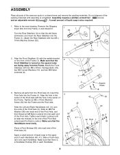
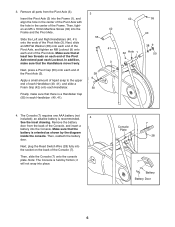
...x 16mm Machine Screw (32) into place. Slide the Left and Right Handlebars (40, 41) onto the ends of the Frame. Then, reattach the battery door. it will not snap into the 42 Frame and the Pivot Axle. The Console (7) requires one AAA battery (not included); Note: The Console is recommended. 4 See the... 32 Hole 1 38 9 50 4. an alkaline battery is held by the diagram inside the console. Next, plug the Reed Switch Wire (28) fully into the Frame (1), and align the hole in the center of the Pivot Axle with the hole in each end of the Pivot Axle extend past each Locknut...
...x 16mm Machine Screw (32) into place. Slide the Left and Right Handlebars (40, 41) onto the ends of the Frame. Then, reattach the battery door. it will not snap into the 42 Frame and the Pivot Axle. The Console (7) requires one AAA battery (not included); Note: The Console is recommended. 4 See the... 32 Hole 1 38 9 50 4. an alkaline battery is held by the diagram inside the console. Next, plug the Reed Switch Wire (28) fully into the Frame (1), and align the hole in the center of the Pivot Axle with the hole in each end of the Pivot Axle extend past each Locknut...
English Manual
Page 7
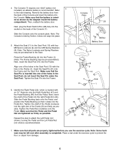
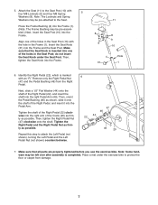
... Right Pedal. Make sure that all parts are properly tightened before you use the exercise bike. Then, tighten the Seat Knob into the Pedal Arm. Then, orient the Pedal Bushing (46) as shown, slide it into the Frame. 11 8 8 9 9 10 4 31 Hole 1 6. Then, tighten the Right Pedal Nut (47) clockwise onto the...: The Frame Bushing may be pre-attached to the Seat Post (10) with an "R." do not insert the Seat Knob under the exercise bike to attach the Left Pedal (not shown), turning the Left Pedal and the Left Pedal Nut (not shown) counterclockwise. 6 47 46 44 22 49 20 7. ...
... Right Pedal. Make sure that all parts are properly tightened before you use the exercise bike. Then, tighten the Seat Knob into the Pedal Arm. Then, orient the Pedal Bushing (46) as shown, slide it into the Frame. 11 8 8 9 9 10 4 31 Hole 1 6. Then, tighten the Right Pedal Nut (47) clockwise onto the...: The Frame Bushing may be pre-attached to the Seat Post (10) with an "R." do not insert the Seat Knob under the exercise bike to attach the Left Pedal (not shown), turning the Left Pedal and the Left Pedal Nut (not shown) counterclockwise. 6 47 46 44 22 49 20 7. ...
English Manual
Page 8
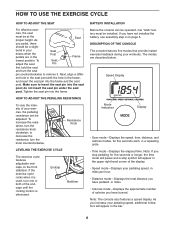
...8 To adjust the seat, first hold the seat and turn the resistance knob clockwise; Tighten the seat knob into the frame and the seat post. If the exercise bike rocks slightly on page 6. Make sure to remove it is used, turn the knob counterclockwise. To increase the resistance, ...the approximate number of your pedaling speed, additional segments will pause and a stop pedaling for five seconds each, in the frame, and insert the seat knob into the frame. to decrease the resistance, turn one or both of the display. • Speed mode-Displays your knees when the...
...8 To adjust the seat, first hold the seat and turn the resistance knob clockwise; Tighten the seat knob into the frame and the seat post. If the exercise bike rocks slightly on page 6. Make sure to remove it is used, turn the knob counterclockwise. To increase the resistance, ...the approximate number of your pedaling speed, additional segments will pause and a stop pedaling for five seconds each, in the frame, and insert the seat knob into the frame. to decrease the resistance, turn one or both of the display. • Speed mode-Displays your knees when the...
English Manual
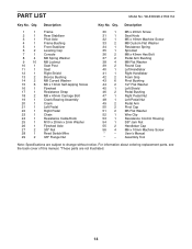
Page 14
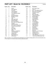
...see the back cover of this manual. *These parts are subject to change without notice. WLEX0996.2 R0411A Key No. Description 1 1 Frame 2 1 Rear Stabilizer 3 1 Pivot Axle 4 1 Frame Bushing 5 1 Front Stabilizer 6 2 Leveling Cap 7 1 Console 8 4 M8 Spring Washer 9 10 M8 Locknut 10 1 Seat... x 40mm Carriage Bolt 19 1 Crank Bearing Assembly 20 1 Crank 21 1 Left Pedal 22 1 Right Pedal 23 1 Chain 24 1 Resistance Cable/Knob 25 1 M10 x 20mm x 2mm Washer 26 1 Flywheel Axle 27 2 3/8" Nut 28 1 Reed Switch/Wire 29 2 3/8" Flange Nut 30 1 M5...
...see the back cover of this manual. *These parts are subject to change without notice. WLEX0996.2 R0411A Key No. Description 1 1 Frame 2 1 Rear Stabilizer 3 1 Pivot Axle 4 1 Frame Bushing 5 1 Front Stabilizer 6 2 Leveling Cap 7 1 Console 8 4 M8 Spring Washer 9 10 M8 Locknut 10 1 Seat... x 40mm Carriage Bolt 19 1 Crank Bearing Assembly 20 1 Crank 21 1 Left Pedal 22 1 Right Pedal 23 1 Chain 24 1 Resistance Cable/Knob 25 1 M10 x 20mm x 2mm Washer 26 1 Flywheel Axle 27 2 3/8" Nut 28 1 Reed Switch/Wire 29 2 3/8" Flange Nut 30 1 M5...