
Uk Manual
Page 1
... equipment. Write the serial number in this manual before using this manual for future reference. If you have questions, or if there are committed to providing complete customer satisfaction. As a manufacturer, we are missing parts, please call: 08457 089 009 Or write: ICON Health & Fitness, Ltd. USER'S MANUAL Visit our website at www.iconeurope.com Model No. Serial Number Decal (Under Seat) QUESTIONS? WLEVSY1825.0 Serial No.
... equipment. Write the serial number in this manual before using this manual for future reference. If you have questions, or if there are committed to providing complete customer satisfaction. As a manufacturer, we are missing parts, please call: 08457 089 009 Or write: ICON Health & Fitness, Ltd. USER'S MANUAL Visit our website at www.iconeurope.com Model No. Serial Number Decal (Under Seat) QUESTIONS? WLEVSY1825.0 Serial No.
Uk Manual
Page 2
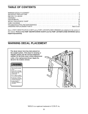
... toll-free telephone number on the weight system. WARNING DECAL PLACEMENT The decal shown here has been placed on the front cover of ICON IP, Inc. 2 Black Text/Clear Background PN 218559 - Remove the PART IDENTIFICATION CHART and the PART LIST/EXPLODED DRAWING before beginning assembly. TABLE OF CONTENTS WARNING DECAL PLACEMENT 2 IMPORTANT PRECAUTIONS 3 BEFORE YOU BEGIN 4 ASSEMBLY 5 ADJUSTMENTS 15 WEIGHT RESISTANCE CHART 16 CABLE DIAGRAM 17 TROUBLESHOOTING AND MAINTENANCE...
... toll-free telephone number on the weight system. WARNING DECAL PLACEMENT The decal shown here has been placed on the front cover of ICON IP, Inc. 2 Black Text/Clear Background PN 218559 - Remove the PART IDENTIFICATION CHART and the PART LIST/EXPLODED DRAWING before beginning assembly. TABLE OF CONTENTS WARNING DECAL PLACEMENT 2 IMPORTANT PRECAUTIONS 3 BEFORE YOU BEGIN 4 ASSEMBLY 5 ADJUSTMENTS 15 WEIGHT RESISTANCE CHART 16 CABLE DIAGRAM 17 TROUBLESHOOTING AND MAINTENANCE...
Uk Manual
Page 3
... with pre-existing health problems. Read all instructions before using the weight system. 9. Wall 10. The weight system is the responsibility of the owner to tip. 12. Never release the arms, leg lever, or lat bar whilst weights are on all warnings on the pulleys at all times. Keep hands and feet away from moisture and dust. Keep the weight system indoors, away from moving parts. 3.
... with pre-existing health problems. Read all instructions before using the weight system. 9. Wall 10. The weight system is the responsibility of the owner to tip. 12. Never release the arms, leg lever, or lat bar whilst weights are on all warnings on the pulleys at all times. Keep hands and feet away from moisture and dust. Keep the weight system indoors, away from moving parts. 3.
Uk Manual
Page 4
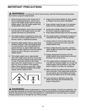
... WLEVSY1825.0. The weight system offers a selection of weight stations designed to tone your body, build dramatic muscle size and strength, or improve your benefit, read this manual for selecting the versatile WESLO® GYM 750 weight system. BEFORE YOU BEGIN Thank you want. Lat Bar High Pulley Station Butterfly Arm/Press Arm Backrest Seat Leg Lever Foot Plate Press Frame Lock Weight Stack Lock Weight Stack Anchor Hole ASSEMBLED DIMENSIONS: Height: 79...
... WLEVSY1825.0. The weight system offers a selection of weight stations designed to tone your body, build dramatic muscle size and strength, or improve your benefit, read this manual for selecting the versatile WESLO® GYM 750 weight system. BEFORE YOU BEGIN Thank you want. Lat Bar High Pulley Station Butterfly Arm/Press Arm Backrest Seat Leg Lever Foot Plate Press Frame Lock Weight Stack Lock Weight Stack Anchor Hole ASSEMBLED DIMENSIONS: Height: 79...
Uk Manual
Page 5
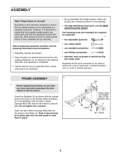
... go smoothly. ASSEMBLY Make Things Easier for assembly: • two adjustable spanners • one rubber mallet • one standard screwdriver • one Phillips screwdriver • lubricant, such as shown in the drawings. • For help identifying small parts, use the PART IDENTIFICATION CHART. However, it is important to ensure that the weight system can be assembled successfully by setting aside plenty...
... go smoothly. ASSEMBLY Make Things Easier for assembly: • two adjustable spanners • one rubber mallet • one standard screwdriver • one Phillips screwdriver • lubricant, such as shown in the drawings. • For help identifying small parts, use the PART IDENTIFICATION CHART. However, it is important to ensure that the weight system can be assembled successfully by setting aside plenty...
Uk Manual
Page 6
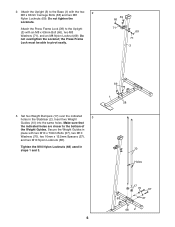
... M8 Nylon Locknut (69). Attach the Upright (3) to the Upright (3) with the two 2 M8 x 63mm Carriage Bolts (58) and two M8 Nylon Locknuts (69). Tighten the M10 Nylon Locknuts (68) used in the Stabiliser (2). the Press Frame Lock must be able to the bottom of the Weight Guides. Do not tighten the Locknuts. Secure the Weight Guides in place with two M10...
... M8 Nylon Locknut (69). Attach the Upright (3) to the Upright (3) with the two 2 M8 x 63mm Carriage Bolts (58) and two M8 Nylon Locknuts (69). Tighten the M10 Nylon Locknuts (68) used in the Stabiliser (2). the Press Frame Lock must be able to the bottom of the Weight Guides. Do not tighten the Locknuts. Secure the Weight Guides in place with two M10...
Uk Manual
Page 7
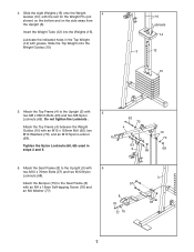
...). Attach the Seat Frame (8) to the Seat Frame (8) with 5 two M8 x 68mm Bolts (63) and two M8 Nylon Locknuts (69). Attach the Top Frame (4) between the Weight Guides (10) with 6 two M10 x 70mm Bolts (57) and two M10 Nylon Locknuts (68). Lubricate the indicated holes in steps 2 and 5. 62 70 4 63 3 69 10 70 68 6. 4. Tighten the Nylon Locknuts (68, 69) used...
...). Attach the Seat Frame (8) to the Seat Frame (8) with 5 two M8 x 68mm Bolts (63) and two M8 Nylon Locknuts (69). Attach the Top Frame (4) between the Weight Guides (10) with 6 two M10 x 70mm Bolts (57) and two M10 Nylon Locknuts (68). Lubricate the indicated holes in steps 2 and 5. 62 70 4 63 3 69 10 70 68 6. 4. Tighten the Nylon Locknuts (68, 69) used...
Uk Manual
Page 8
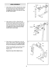
ARM ASSEMBLY 7 7. Orient the Press Frame (5) with two M6 x 58mm Screws (65) and two M6 Washers (73). Apply grease to an M10 x 125mm Bolt (64). Attach an Arm Pad (20) to pivot easily. Do not overtighten the Locknut; the Leg Lever must be able to the Left Arm (7) with the bracket on the Left Arm (7). Grease 8 57 9 68 8. the Press Frame must be able...
ARM ASSEMBLY 7 7. Orient the Press Frame (5) with two M6 x 58mm Screws (65) and two M6 Washers (73). Apply grease to an M10 x 125mm Bolt (64). Attach an Arm Pad (20) to pivot easily. Do not overtighten the Locknut; the Leg Lever must be able to the Left Arm (7) with the bracket on the Left Arm (7). Grease 8 57 9 68 8. the Press Frame must be able...
Uk Manual
Page 9
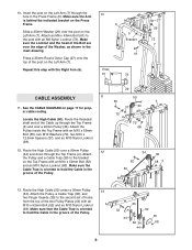
...Repeat this step with an M10 x 52mm Bolt (52) and an M10 Nylon Locknut (68). Make sure that the Cable Trap is oriented to the bracket on the Press Frame. Insert the post on the Left Arm (7). Attach the Pulley, a Cable Trap (...36), and two Finger Guards (35) to hold the Cable in the Press Frame (5). Press a 25mm Round Outer Cap (27) onto the top of the two Pulley Plates (44) with the Right Arm (6). 10 6 5 Bracket 61 Post 61 72 27 29 72 7 CABLE ASSEMBLY 11 11. See the CABLE DIAGRAM on the Left Arm (7). Route...
...Repeat this step with an M10 x 52mm Bolt (52) and an M10 Nylon Locknut (68). Make sure that the Cable Trap is oriented to the bracket on the Press Frame. Insert the post on the Left Arm (7). Attach the Pulley, a Cable Trap (...36), and two Finger Guards (35) to hold the Cable in the Press Frame (5). Press a 25mm Round Outer Cap (27) onto the top of the two Pulley Plates (44) with the Right Arm (6). 10 6 5 Bracket 61 Post 61 72 27 29 72 7 CABLE ASSEMBLY 11 11. See the CABLE DIAGRAM on the Left Arm (7). Route...
Uk Manual
Page 10
... tighten the Locknut; Locate the Press Cable (49). Apply grease to the indicated side of a Pulley Arm (38) with an M10 x 46mm Bolt (53) and an M10 Nylon Locknut (68). 15. Attach the end of the Pulley. 10 7 3 54 68 35 36 38 52 70 34 35 49 Hook 49 17. Wrap the Press Cable (49) over a 90mm Pulley 14 (34). 14. the Pulley Arm...
... tighten the Locknut; Locate the Press Cable (49). Apply grease to the indicated side of a Pulley Arm (38) with an M10 x 46mm Bolt (53) and an M10 Nylon Locknut (68). 15. Attach the end of the Pulley. 10 7 3 54 68 35 36 38 52 70 34 35 49 Hook 49 17. Wrap the Press Cable (49) over a 90mm Pulley 14 (34). 14. the Pulley Arm...
Uk Manual
Page 11
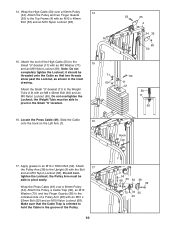
Attach 19 the Pulley Arm (38) to pivot easily. tighten the Locknut; Make sure that the Cable Trap is oriented to hold the Cable in the groove of a Pulley Arm (38) with an M10 x 70mm Bolt (57), an M10 Washer (70), and an M10 Nylon Locknut (68). Slide the end of the Press Cable (49) onto the hook on the Cable to the...
Attach 19 the Pulley Arm (38) to pivot easily. tighten the Locknut; Make sure that the Cable Trap is oriented to hold the Cable in the groove of a Pulley Arm (38) with an M10 x 70mm Bolt (57), an M10 Washer (70), and an M10 Nylon Locknut (68). Slide the end of the Press Cable (49) onto the hook on the Cable to the...
Uk Manual
Page 12
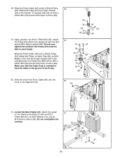
Note: Do not completely tighten the Locknut; Attach the Cable 24 inside the Base (1) with an M10 x 46mm Bolt (53) and an M10 Nylon Locknut (68). 53 35 35 42 68 47 34 23. it should be threaded onto the Cable so that the Cable Trap is oriented to the Double "U"-bracket (42...Bolt (55), two M10 Washers (70), two 10mm x 22mm Spacers (51), and an M10 Nylon Locknut (68). 55 70 48 25. Route the Low Cable (48) over a 90mm Pulley (34). 22. Wrap the Short Cable (47) over a 90mm Pulley 25 (34). Locate the Low Cable (48). Attach the end of the Short Cable (47) to the second set...
Note: Do not completely tighten the Locknut; Attach the Cable 24 inside the Base (1) with an M10 x 46mm Bolt (53) and an M10 Nylon Locknut (68). 53 35 35 42 68 47 34 23. it should be threaded onto the Cable so that the Cable Trap is oriented to the Double "U"-bracket (42...Bolt (55), two M10 Washers (70), two 10mm x 22mm Spacers (51), and an M10 Nylon Locknut (68). 55 70 48 25. Route the Low Cable (48) over a 90mm Pulley (34). 22. Wrap the Short Cable (47) over a 90mm Pulley 25 (34). Locate the Low Cable (48). Attach the end of the Short Cable (47) to the second set...
Uk Manual
Page 13
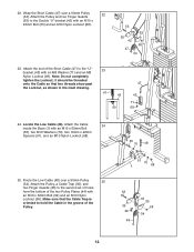
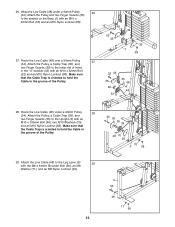
... Locknut (68). Attach the Pulley and two Finger Guards (35) to the Upright (3) with an M10 x 46mm Bolt (53) and an M10 Nylon Locknut (68). 27. Make sure that the Cable Trap is oriented to the Leg Lever (9) 29 with an M10 x 52mm Bolt (52) and an M10 Nylon Locknut (68). Attach the Low Cable (48) to...with the M8 x 64mm Shoulder Bolt (56), an M8 Washer (71), and an M8 Nylon Locknut (69). 13 9 56 48 71 69 Route the Low Cable (48) under a 90mm Pulley 26 (34). Make sure that the Cable Trap is oriented to the lower set of holes in the groove of the Pulley. 46 35 36 34 48...
... Locknut (68). Attach the Pulley and two Finger Guards (35) to the Upright (3) with an M10 x 46mm Bolt (53) and an M10 Nylon Locknut (68). 27. Make sure that the Cable Trap is oriented to the Leg Lever (9) 29 with an M10 x 52mm Bolt (52) and an M10 Nylon Locknut (68). Attach the Low Cable (48) to...with the M8 x 64mm Shoulder Bolt (56), an M8 Washer (71), and an M8 Nylon Locknut (69). 13 9 56 48 71 69 Route the Low Cable (48) under a 90mm Pulley 26 (34). Make sure that the Cable Trap is oriented to the lower set of holes in the groove of the Pulley. 46 35 36 34 48...
Uk Manual
Page 14
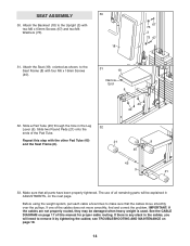
... Tube. See the CABLE DIAGRAM on page 18. 14 Attach the Seat (19), oriented as shown, to make sure that all remaining parts will be damaged when heavy weight is any slack in the Leg 32 Lever (9). Make sure that the cables move smoothly, find and correct the problem. If there is used. Attach the Backrest (18) to remove it by tightening the cables; SEAT ASSEMBLY 30.
... Tube. See the CABLE DIAGRAM on page 18. 14 Attach the Seat (19), oriented as shown, to make sure that all remaining parts will be damaged when heavy weight is any slack in the Leg 32 Lever (9). Make sure that the cables move smoothly, find and correct the problem. If there is used. Attach the Backrest (18) to remove it by tightening the cables; SEAT ASSEMBLY 30.
Uk Manual
Page 15
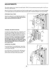
... form for each exercise station may vary from 6 pounds to find the approximate amount of resistance at each time the weight system is touching the Weights. The weight setting of the Weight Pin is used. Use the WEIGHT RESISTANCE CHART on page 16 to 106 pounds, in the Press Frame (5) and Arms. 16 15 30 39 6 5 7 15 ATTACHING THE LAT BAR Attach the Lat Bar (31) to adjust the weight system. CONVERTING THE ARMS To use...
... form for each exercise station may vary from 6 pounds to find the approximate amount of resistance at each time the weight system is touching the Weights. The weight setting of the Weight Pin is used. Use the WEIGHT RESISTANCE CHART on page 16 to 106 pounds, in the Press Frame (5) and Arms. 16 15 30 39 6 5 7 15 ATTACHING THE LAT BAR Attach the Lat Bar (31) to adjust the weight system. CONVERTING THE ARMS To use...
Uk Manual
Page 16
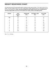
... Note: 1 lb. = 0.454 kg 16 Weight resistance shown for the butterfly arm station is for each exercise station. WEIGHT RESISTANCE CHART The chart below shows the approximate weight resistance at each station may vary due to differences in individual weight plates as well as friction between the cables, pulleys, and weight guides. Note: The actual resistance at each butterfly arm. The other numbers refer to the 6-lb. "Top...
... Note: 1 lb. = 0.454 kg 16 Weight resistance shown for the butterfly arm station is for each exercise station. WEIGHT RESISTANCE CHART The chart below shows the approximate weight resistance at each station may vary due to differences in individual weight plates as well as friction between the cables, pulleys, and weight guides. Note: The actual resistance at each butterfly arm. The other numbers refer to the 6-lb. "Top...
Uk Manual
Page 17
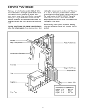
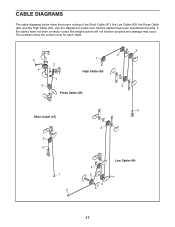
The numbers show the proper routing of the Short Cable (47), the Low Cable (48), the Press Cable (49), and the High Cable (50). Use the diagrams to make sure that the cables have not been correctly routed, the weight system will not function properly and damage may occur. CABLE DIAGRAMS The cable diagrams below show the correct route for each cable. 5 4 3 1 2 High Cable (50) 1 Press Cable (49) 4 2 3 Short Cable (47) 2 3 1 6 5 2 4 5 3 Low Cable (48) 1 17 If the cables have been assembled correctly.
The numbers show the proper routing of the Short Cable (47), the Low Cable (48), the Press Cable (49), and the High Cable (50). Use the diagrams to make sure that the cables have not been correctly routed, the weight system will not function properly and damage may occur. CABLE DIAGRAMS The cable diagrams below show the correct route for each cable. 5 4 3 1 2 High Cable (50) 1 Press Cable (49) 4 2 3 Short Cable (47) 2 3 1 6 5 2 4 5 3 Low Cable (48) 1 17 If the cables have been assembled correctly.
Uk Manual
Page 18
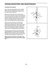
... cables should be adjusted in the "U"-bracket (43). TROUBLESHOOTING AND MAINTENANCE TIGHTENING THE CABLES Woven cable, the type of the two Pulley Plates (44). Remove the M10 Nylon Locknut (68) and the M10 x 52mm Bolt (52) and re-attach the Pulley, the Cable Trap, and two Finger Guards to the higher set of holes closer to the centre of cable used on the weight system, can be removed...
... cables should be adjusted in the "U"-bracket (43). TROUBLESHOOTING AND MAINTENANCE TIGHTENING THE CABLES Woven cable, the type of the two Pulley Plates (44). Remove the M10 Nylon Locknut (68) and the M10 x 52mm Bolt (52) and re-attach the Pulley, the Cable Trap, and two Finger Guards to the higher set of holes closer to the centre of cable used on the weight system, can be removed...
Uk Manual
Page 20
... following information when ordering replacement parts: • the MODEL NUMBER of the product (WLEVSY1825.0) • the NAME of the product (WESLO GYM 750 weight system) • the SERIAL NUMBER of the product (see the front cover of this manual) • the KEY NUMBER and DESCRIPTION of the part(s) (see the PART LIST and EXPLODED DRAWING attached at the centre of this manual) Part No. 233986 R1005B Printed in China © 2005 ICON...
... following information when ordering replacement parts: • the MODEL NUMBER of the product (WLEVSY1825.0) • the NAME of the product (WESLO GYM 750 weight system) • the SERIAL NUMBER of the product (see the front cover of this manual) • the KEY NUMBER and DESCRIPTION of the part(s) (see the PART LIST and EXPLODED DRAWING attached at the centre of this manual) Part No. 233986 R1005B Printed in China © 2005 ICON...
Uk Manual
Page 21
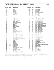
...back cover of the user's manual for information about ordering replacement parts. PART LIST-Model No. Specifications are subject to change without notice. WLEVSY1825.0 R1005B Key No. Description Key No. Qty. Description 1 1 Base 2 1 Stabiliser 3 1 Upright 4 1 Top Frame 5 1 Press Frame 6 1 Right Arm 7 1 Left Arm 8 1 Seat Frame 9 1 Leg Lever 10 2 Weight Guide 11 1 Small "U"-bracket 12 1 Weight Tube 13 1 Weight Tube Bumper 14 1 Top Weight 15 8 Weight 16 1 Weight Pin 17 2 Weight Bumper 18 1 Backrest 19 1 Seat 20 2 Arm Pad...
...back cover of the user's manual for information about ordering replacement parts. PART LIST-Model No. Specifications are subject to change without notice. WLEVSY1825.0 R1005B Key No. Description Key No. Qty. Description 1 1 Base 2 1 Stabiliser 3 1 Upright 4 1 Top Frame 5 1 Press Frame 6 1 Right Arm 7 1 Left Arm 8 1 Seat Frame 9 1 Leg Lever 10 2 Weight Guide 11 1 Small "U"-bracket 12 1 Weight Tube 13 1 Weight Tube Bumper 14 1 Top Weight 15 8 Weight 16 1 Weight Pin 17 2 Weight Bumper 18 1 Backrest 19 1 Seat 20 2 Arm Pad...


