
Uk Manual
Page 1
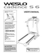
WETL14906.0 Serial No. USER'S MANUAL Serial Number Decal QUESTIONS? If you have questions, or if there are committed to providing complete customer satisfaction. Customer Service Department Unit 4 Revie Road Industrial Estate Revie Road Beeston Leeds, LS118JG UK email: [email protected] CAUTION Read all precautions and instructions in this manual before using this manual for future reference. As a manufacturer, we are missing or damaged parts, please call: 08457 089 009 or write: ICON Health & Fitness, Ltd. Model No. Save this equipment.
WETL14906.0 Serial No. USER'S MANUAL Serial Number Decal QUESTIONS? If you have questions, or if there are committed to providing complete customer satisfaction. Customer Service Department Unit 4 Revie Road Industrial Estate Revie Road Beeston Leeds, LS118JG UK email: [email protected] CAUTION Read all precautions and instructions in this manual before using this manual for future reference. As a manufacturer, we are missing or damaged parts, please call: 08457 089 009 or write: ICON Health & Fitness, Ltd. Model No. Save this equipment.

Uk Manual
Page 2
WESLO is a registered trademark of this manual. TABLE OF CONTENTS IMPORTANT PRECAUTIONS 3 BEFORE YOU BEGIN 5 ASSEMBLY 6 OPERATION AND ADJUSTMENT 10 HOW TO FOLD AND MOVE THE TREADMILL 15 MAINTENANCE AND TROUBLESHOOTING 17 CONDITIONING GUIDELINES 19 ORDERING REPLACEMENT PARTS Back Cover Note: A PART IDENTIFICATION CHART, an EXPLODED DRAWING, and a PART LIST are attached in the center of ICON IP, Inc. 2
WESLO is a registered trademark of this manual. TABLE OF CONTENTS IMPORTANT PRECAUTIONS 3 BEFORE YOU BEGIN 5 ASSEMBLY 6 OPERATION AND ADJUSTMENT 10 HOW TO FOLD AND MOVE THE TREADMILL 15 MAINTENANCE AND TROUBLESHOOTING 17 CONDITIONING GUIDELINES 19 ORDERING REPLACEMENT PARTS Back Cover Note: A PART IDENTIFICATION CHART, an EXPLODED DRAWING, and a PART LIST are attached in the center of ICON IP, Inc. 2
Uk Manual
Page 3
... 10), plug the power cord into an earthed circuit. Always remove the key and unplug the power cord when the treadmill is capable of heart rate readings. The pulse sensor is intended only as described in use only a 3conductor, 1mm2 (14-gauge) cord that is properly assembled. (See ASSEMBLY on page 6, and HOW TO FOLD AND MOVE THE TREADMILL on page 10). 5. Do not place the treadmill on the walking belt. To...
... 10), plug the power cord into an earthed circuit. Always remove the key and unplug the power cord when the treadmill is capable of heart rate readings. The pulse sensor is intended only as described in use only a 3conductor, 1mm2 (14-gauge) cord that is properly assembled. (See ASSEMBLY on page 6, and HOW TO FOLD AND MOVE THE TREADMILL on page 10). 5. Do not place the treadmill on the walking belt. To...
Uk Manual
Page 4
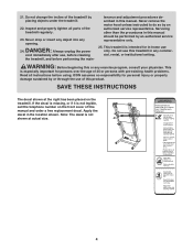
... in the location shown. 21. tenance and adjustment procedures described in any commercial, rental, or institutional setting. SAVE THESE INSTRUCTIONS The decal shown at actual size. Do not change the incline of this manual. Inspect and properly tighten all parts of 35 or persons with pre-existing health problems. Read all instructions before performing the main- Always unplug the power cord immediately after use this treadmill in...
... in the location shown. 21. tenance and adjustment procedures described in any commercial, rental, or institutional setting. SAVE THESE INSTRUCTIONS The decal shown at actual size. Do not change the incline of this manual. Inspect and properly tighten all parts of 35 or persons with pre-existing health problems. Read all instructions before performing the main- Always unplug the power cord immediately after use this treadmill in...
Uk Manual
Page 5
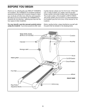
... manual for selecting the new WESLO® CADENCE S 6 treadmill. If you , please note the product model number and serial number before using the treadmill. To help us . The model number of other treadmills. BEFORE YOU BEGIN Thank you 're not exercising, the CADENCE S 6 treadmill can be folded up, requiring less than half the floor space of the treadmill is not included) Handrail Console Key/Clip Storage Latch Walking Belt Hood On/Off Switch Circuit Breaker Foot Rail Rear Roller Adjustment Bolts Incline Leg...
... manual for selecting the new WESLO® CADENCE S 6 treadmill. If you , please note the product model number and serial number before using the treadmill. To help us . The model number of other treadmills. BEFORE YOU BEGIN Thank you 're not exercising, the CADENCE S 6 treadmill can be folded up, requiring less than half the floor space of the treadmill is not included) Handrail Console Key/Clip Storage Latch Walking Belt Hood On/Off Switch Circuit Breaker Foot Rail Rear Roller Adjustment Bolts Incline Leg...

Uk Manual
Page 6
... not dispose of the Wheel Bolts (35) on top of the treadmill walking belt is coated with 54 two Upright Bolts (2). Some parts may be preassembled. 1. Do not tighten the Upright Bolts yet. 2 Attach the Right Upright (54) to the included hex key , assembly requires a phillips screwdriver spanners , and wire cutters . , two Note: To identify small parts used during assembly, see the PART IDENTIFICATION CHART in the posi- Slide the...
... not dispose of the Wheel Bolts (35) on top of the treadmill walking belt is coated with 54 two Upright Bolts (2). Some parts may be preassembled. 1. Do not tighten the Upright Bolts yet. 2 Attach the Right Upright (54) to the included hex key , assembly requires a phillips screwdriver spanners , and wire cutters . , two Note: To identify small parts used during assembly, see the PART IDENTIFICATION CHART in the posi- Slide the...

Uk Manual
Page 7
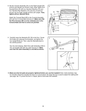
...Console Assembly. Repeat this step on the left side of the treadmill. Attach the Right Handrail (55) to scratch the face of the Frame (51). Next, locate the opposite end of the Right Upright. Hold a Frame Spacer (111) between the Uprights. Remove the wire from the upper end of the wire... one side. Locate the wire inside the lower end of the treadmill. Turn the Console Assembly (91) face-down. With the help of the treadmill Frame (51) between the Right Upright (54) and the Frame. Secure the wire to the Frame with two Console Screws (4), a Crossbar Screw (5), and a...
...Console Assembly. Repeat this step on the left side of the treadmill. Attach the Right Handrail (55) to scratch the face of the Frame (51). Next, locate the opposite end of the Right Upright. Hold a Frame Spacer (111) between the Uprights. Remove the wire from the upper end of the wire... one side. Locate the wire inside the lower end of the treadmill. Turn the Console Assembly (91) face-down. With the help of the treadmill Frame (51) between the Right Upright (54) and the Frame. Secure the wire to the Frame with two Console Screws (4), a Crossbar Screw (5), and a...

Uk Manual
Page 8
... 98 Plastic Ties 98 7. Then, attach the Left Handrail (56) to pinch the ground wire. 5 5 12 4 Small Hole 56 Console Ground Wire 8 91 6. IF THE CONNECTOR IS NOT INSERTED PROPERLY, THE CONSOLE MAY BE DAMAGED WHEN THE POWER IS TURNED ON. The end of the Wire Harness (98) into the Right Upright (54). Then, tighten the two plastic ties around...
... 98 Plastic Ties 98 7. Then, attach the Left Handrail (56) to pinch the ground wire. 5 5 12 4 Small Hole 56 Console Ground Wire 8 91 6. IF THE CONNECTOR IS NOT INSERTED PROPERLY, THE CONSOLE MAY BE DAMAGED WHEN THE POWER IS TURNED ON. The end of the Wire Harness (98) into the Right Upright (54). Then, tighten the two plastic ties around...
Uk Manual
Page 9
... in a secure place; 8. Set the Console Assembly (91) on the Right Upright (54) and the Left Upright (not shown). Then, tighten all parts are properly tightened before you use the treadmill. Carefully lower the Handrails (55, 56) to the vertical position. 51 2 See the inset drawing. Attach the Console Back (93) to the Console Assembly (91) with two Latch Screws (7). Attach the Latch Assembly (108) to adjust the walking belt (see page 18...
... in a secure place; 8. Set the Console Assembly (91) on the Right Upright (54) and the Left Upright (not shown). Then, tighten all parts are properly tightened before you use the treadmill. Carefully lower the Handrails (55, 56) to the vertical position. 51 2 See the inset drawing. Attach the Console Back (93) to the Console Assembly (91) with two Latch Screws (7). Attach the Latch Assembly (108) to adjust the walking belt (see page 18...

Uk Manual
Page 10
... other substances to reduce the risk of least resistance for electric cur- 1 rent to the walking belt or the walking platform. Outlet IT GR DANGER: Improper connection of the power cord and tighten the screw in the adapter as IT to whether the product is secure and the screw has been tightened before using the power cord. 2 Screw Adapter Cover Pins Adapter Metal Clips FR/ See drawing 3. This product is...
... other substances to reduce the risk of least resistance for electric cur- 1 rent to the walking belt or the walking platform. Outlet IT GR DANGER: Improper connection of the power cord and tighten the screw in the adapter as IT to whether the product is secure and the screw has been tightened before using the power cord. 2 Screw Adapter Cover Pins Adapter Metal Clips FR/ See drawing 3. This product is...
Uk Manual
Page 11
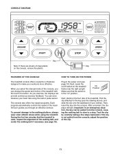
... controls the speed of the treadmill. Plug in pulse sensor. On Position Next, stand on the console, remove the plastic. FEATURES OF THE CONSOLE HOW TO TURN ON THE POWER The treadmill console offers a selection of the walking belt, and center the walking belt if necessary (see page 10). As you through an effective workout. During the first few steps backward; Next, locate the on/off switch on " position. if the key...
... controls the speed of the treadmill. Plug in pulse sensor. On Position Next, stand on the console, remove the plastic. FEATURES OF THE CONSOLE HOW TO TURN ON THE POWER The treadmill console offers a selection of the walking belt, and center the walking belt if necessary (see page 10). As you through an effective workout. During the first few steps backward; Next, locate the on/off switch on " position. if the key...

Uk Manual
Page 12
... treadmill as desired by pressing the Speed increase and decrease buttons. if you use the handgrip pulse sensor (see step 6 on page 11. 2 Select the manual mode. The time will change by pressing the Program Select button repeatedly until the upper display shows the information that you have completed. The display also shows your progress with the track and the displays. To reset the displays, press the Stop button, remove the key, and then reinsert the key...
... treadmill as desired by pressing the Speed increase and decrease buttons. if you use the handgrip pulse sensor (see step 6 on page 11. 2 Select the manual mode. The time will change by pressing the Program Select button repeatedly until the upper display shows the information that you have completed. The display also shows your progress with the track and the displays. To reset the displays, press the Stop button, remove the key, and then reinsert the key...

Uk Manual
Page 13
... the power cord. 13 Metal Contacts To measure your heart rate, stand on /off switch to change the unit of clear plastic from the console. Next, hold the metal contacts-avoid moving your hands are finished exercising, remove the key from the console. Before using the handgrip pulse sensor, remove the sheets of measurement if desired. Step onto the foot rails, press the Stop button, and remove the key from the console. Then, switch...
... the power cord. 13 Metal Contacts To measure your heart rate, stand on /off switch to change the unit of clear plastic from the console. Next, hold the metal contacts-avoid moving your hands are finished exercising, remove the key from the console. Before using the handgrip pulse sensor, remove the sheets of measurement if desired. Step onto the foot rails, press the Stop button, and remove the key from the console. Then, switch...
Uk Manual
Page 14
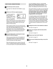
... walking belt will continue until all 30 periods are finished exercising, remove the key. See step 6 on page 12. 5 Follow your heart rate if desired. To restart the program, press the Start button or the Speed increase button. See step 4 on page 13. 7 When you press either button, the treadmill will change if a different speed setting is programmed for the second period, the speed setting will change . HOW TO USE A SPEED PROGRAM 1 Insert the key into the console. One speed setting is programmed...
... walking belt will continue until all 30 periods are finished exercising, remove the key. See step 6 on page 12. 5 Follow your heart rate if desired. To restart the program, press the Start button or the Speed increase button. See step 4 on page 13. 7 When you press either button, the treadmill will change if a different speed setting is programmed for the second period, the speed setting will change . HOW TO USE A SPEED PROGRAM 1 Insert the key into the console. One speed setting is programmed...

Uk Manual
Page 15
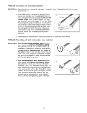
..., use extreme caution while moving the treadmill, convert the treadmill to bend your legs and keep your back. Never move the treadmill to the vertical position. Raise the frame until it is past the latch pin. HOW TO MOVE THE TREADMILL Before moving the treadmill. To reduce the risk of the wheels. HOW TO FOLD AND MOVE THE TREADMILL HOW TO FOLD THE TREADMILL FOR STORAGE Unplug the power cord. Tilt...
..., use extreme caution while moving the treadmill, convert the treadmill to bend your legs and keep your back. Never move the treadmill to the vertical position. Raise the frame until it is past the latch pin. HOW TO MOVE THE TREADMILL Before moving the treadmill. To reduce the risk of the wheels. HOW TO FOLD AND MOVE THE TREADMILL HOW TO FOLD THE TREADMILL FOR STORAGE Unplug the power cord. Tilt...
Uk Manual
Page 17
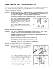
... steps below. d. c Tripped Reset d On Position PROBLEM: The power turns off during use only a 3-conductor, 1 mm2 (14-gauge) cord that the key is plugged in . Then, care- 20 fully remove the Hood (65). 20 25 Locate the Reed Switch (97) and the Magnet (105) on the treadmill near the power cord. If further assistance is needed , please see the front cover of the console do not function properly SOLUTION: a. MAINTENANCE AND TROUBLESHOOTING...
... steps below. d. c Tripped Reset d On Position PROBLEM: The power turns off during use only a 3-conductor, 1 mm2 (14-gauge) cord that the key is plugged in . Then, care- 20 fully remove the Hood (65). 20 25 Locate the Reed Switch (97) and the Magnet (105) on the treadmill near the power cord. If further assistance is needed , please see the front cover of the console do not function properly SOLUTION: a. MAINTENANCE AND TROUBLESHOOTING...
Uk Manual
Page 18
... walking belt centered. Using the allen wrench, turn both rear roller bolts clockwise, 1/4 of a turn . b 5-7cm Rear Roller Bolts c. If the walking belt has shifted to the right, turn the left rear roller bolt counterclockwise 1/2 of a turn . b. PROBLEM: The walking belt is centered. Repeat until the walking belt is properly tightened, you should be able to lift each edge of this manual. If the walking belt slips when walked on SOLUTION: a. Then, plug in the power cord, insert the key, and run the treadmill...
... walking belt centered. Using the allen wrench, turn both rear roller bolts clockwise, 1/4 of a turn . b 5-7cm Rear Roller Bolts c. If the walking belt has shifted to the right, turn the left rear roller bolt counterclockwise 1/2 of a turn . b. PROBLEM: The walking belt is centered. Repeat until the walking belt is properly tightened, you should be able to lift each edge of this manual. If the walking belt slips when walked on SOLUTION: a. Then, plug in the power cord, insert the key, and run the treadmill...
Uk Manual
Page 19
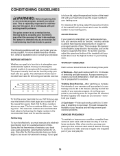
... incline of your training zone. This is near the highest number in your everyday life. 19 CONDITIONING GUIDELINES WARNING: Before beginning this or any exercise program, consult your physician. The lower two numbers are rounded off to burn fat, adjust the speed and incline of the treadmill until your heart rate is not a medical device. The key to success is intended only as a guide. The sensor...
... incline of your training zone. This is near the highest number in your everyday life. 19 CONDITIONING GUIDELINES WARNING: Before beginning this or any exercise program, consult your physician. The lower two numbers are rounded off to burn fat, adjust the speed and incline of the treadmill until your heart rate is not a medical device. The key to success is intended only as a guide. The sensor...
Uk Manual
Page 20
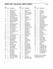
... Grommet Stop Bracket Controller Transformer Filter Power Cord Console Assembly Console Crossbar Console Back Wheel Nut Ground Wire Ground Wire Reed Switch Wire Harness Outlet Plate Assembly Walking Platform Walking Belt Lift Motor Nut Belt Guide Front Roller/Pulley Magnet Motor Belt Rear Roller Latch Assembly Key/Clip Incline Bolt Frame Spacer Power Adapter Warning Decal Tie Holder Screw Lift Belly Pan Incline Wire Shield Incline Motor 6" Red Wire, M/F 4" Black Wire, M/F 4" Blue Wire, M/F 8" Blue Wire, 2F 10" Blue Wire, 2F 6" White Wire, 2F 10" White Wire, 2F User's Manual #These parts are...
... Grommet Stop Bracket Controller Transformer Filter Power Cord Console Assembly Console Crossbar Console Back Wheel Nut Ground Wire Ground Wire Reed Switch Wire Harness Outlet Plate Assembly Walking Platform Walking Belt Lift Motor Nut Belt Guide Front Roller/Pulley Magnet Motor Belt Rear Roller Latch Assembly Key/Clip Incline Bolt Frame Spacer Power Adapter Warning Decal Tie Holder Screw Lift Belly Pan Incline Wire Shield Incline Motor 6" Red Wire, M/F 4" Black Wire, M/F 4" Blue Wire, M/F 8" Blue Wire, 2F 10" Blue Wire, 2F 6" White Wire, 2F 10" White Wire, 2F User's Manual #These parts are...
Uk Manual
Page 23
... of the product (WESLO CADENCE S 6 treadmill) • the SERIAL NUMBER of the product (see the front cover of this manual) • the KEY NUMBER and DESCRIPTION of the needed part(s) (see the PART LIST and the EXPLODED DRAWING in the centre of this manual) Part No. 237122 R0806A Printed in China © 2006 ICON IP, Inc. ORDERING REPLACEMENT PARTS To order replacement parts, contact the ICON Health & Fitness, Ltd. office, or write: ICON Health & Fitness, Ltd.
... of the product (WESLO CADENCE S 6 treadmill) • the SERIAL NUMBER of the product (see the front cover of this manual) • the KEY NUMBER and DESCRIPTION of the needed part(s) (see the PART LIST and the EXPLODED DRAWING in the centre of this manual) Part No. 237122 R0806A Printed in China © 2006 ICON IP, Inc. ORDERING REPLACEMENT PARTS To order replacement parts, contact the ICON Health & Fitness, Ltd. office, or write: ICON Health & Fitness, Ltd.


