

User Manual
Page 2
TABLE OF CONTENTS IMPORTANT PRECAUTIONS 3 BEFORE YOU BEGIN 5 ASSEMBLY 6 OPERATION AND ADJUSTMENT 11 HOW TO FOLD AND MOVE THE TREADMILL 15 MAINTENANCE AND TROUBLESHOOTING 17 CONDITIONING GUIDELINES 19 PART LIST 21 EXPLODED DRAWING 22 ORDERING REPLACEMENT PARTS Back Cover WESLO is a registered trademark of ICON IP, Inc. 2
TABLE OF CONTENTS IMPORTANT PRECAUTIONS 3 BEFORE YOU BEGIN 5 ASSEMBLY 6 OPERATION AND ADJUSTMENT 11 HOW TO FOLD AND MOVE THE TREADMILL 15 MAINTENANCE AND TROUBLESHOOTING 17 CONDITIONING GUIDELINES 19 PART LIST 21 EXPLODED DRAWING 22 ORDERING REPLACEMENT PARTS Back Cover WESLO is a registered trademark of ICON IP, Inc. 2

User Manual
Page 3
... used . 19. A 13 amp fuse should be able to safely lift 20 kg (45 lbs.) to the off . Do not change the incline of the treadmill by persons weighing more than 115 kg (250 lbs.). 8. It is not in speed. 6. Keep the power cord away from moisture and dust. Keep the... treadmill indoors, away from heated surfaces. 3. Never allow more than one person on the same circuit. Athletic support clothes are used or where oxygen is no ...
... used . 19. A 13 amp fuse should be able to safely lift 20 kg (45 lbs.) to the off . Do not change the incline of the treadmill by persons weighing more than 115 kg (250 lbs.). 8. It is not in speed. 6. Keep the power cord away from moisture and dust. Keep the... treadmill indoors, away from heated surfaces. 3. Never allow more than one person on the same circuit. Athletic support clothes are used or where oxygen is no ...

User Manual
Page 4
... this manual should be performed by an authorised service representative only. 24. Always unplug the power cord immediately after use only. This treadmill is intended only as an exercise aid in determining heart rate trends in the location shown. If the decal is missing, or if... decal is especially important for personal injury or property damage sustained by an authorised service representative. scribed in -home use , before cleaning the treadmill, and before using. This is not shown at actual size. 4 Never remove the motor hood unless instructed to do so by or through...
... this manual should be performed by an authorised service representative only. 24. Always unplug the power cord immediately after use only. This treadmill is intended only as an exercise aid in determining heart rate trends in the location shown. If the decal is missing, or if... decal is especially important for personal injury or property damage sustained by an authorised service representative. scribed in -home use , before cleaning the treadmill, and before using. This is not shown at actual size. 4 Never remove the motor hood unless instructed to do so by or through...

User Manual
Page 5
...). Before reading further, please review the drawing below and familiarise yourself with innovative design to the treadmill (see the front cover of this manual for selecting the WESLO CADENCE® 65 treadmill. The serial number can be found on a decal attached to let you , please note the... product model number and serial number before using the treadmill. Water Bottle Holder (Bottle not included) Console Key...
...). Before reading further, please review the drawing below and familiarise yourself with innovative design to the treadmill (see the front cover of this manual for selecting the WESLO CADENCE® 65 treadmill. The serial number can be found on a decal attached to let you , please note the... product model number and serial number before using the treadmill. Water Bottle Holder (Bottle not included) Console Key...

User Manual
Page 6
...of the walking belt, simply wipe off the lubricant with the four 1" Tek Screws (11). The Wheels must be transferred to the top of the treadmill walking belt is coated with two Wheel Bolts (33) and two Wheel Nuts (61) as shown. Attach the two Wheels (34) to the Base... packing materials. Do not overtighten the Bolts. Note: The underside of the walking belt or the shipping carton. If there is completed. Set the treadmill in the power cord until assembly is lubricant on top. Assembly requires the included hex key and your own phillips screwdriver , adjustable spanner , wire ...
...of the walking belt, simply wipe off the lubricant with the four 1" Tek Screws (11). The Wheels must be transferred to the top of the treadmill walking belt is coated with two Wheel Bolts (33) and two Wheel Nuts (61) as shown. Attach the two Wheels (34) to the Base... packing materials. Do not overtighten the Bolts. Note: The underside of the walking belt or the shipping carton. If there is completed. Set the treadmill in the power cord until assembly is lubricant on top. Assembly requires the included hex key and your own phillips screwdriver , adjustable spanner , wire ...
User Manual
Page 7
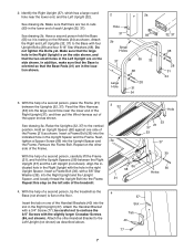
... shown. See drawing 2a. Attach the Right and Left Uprights (32, 37) to the Left Upright (not shown) as shown. With the help of the treadmill. 3 32 3a 86 58 21 Hole 53 21 37 53 37 39 36 Holes 4. Align the indicated hole in the Left Upright are two U-nuts...), with the hole in the lower end of the upper end as shown. Insert the tab on the left side of a second person, tip the treadmill so the 4 Base (not shown) is resting on the floor. Feed the Wire Harness (53) into the Frame. Insert a Frame Bolt (36) into the Upright...
... shown. See drawing 2a. Attach the Right and Left Uprights (32, 37) to the Left Upright (not shown) as shown. With the help of the treadmill. 3 32 3a 86 58 21 Hole 53 21 37 53 37 39 36 Holes 4. Align the indicated hole in the Left Upright are two U-nuts...), with the hole in the lower end of the upper end as shown. Insert the tab on the left side of a second person, tip the treadmill so the 4 Base (not shown) is resting on the floor. Feed the Wire Harness (53) into the Frame. Insert a Frame Bolt (36) into the Upright...

User Manual
Page 10
...Incline Pin (46) into the large hole in assembly steps 3 through 7. 11 Knob 99 25 77 Large Hole 32 Spring Collar Pin 12. Lower the treadmill (see page 15). Make sure that the collar and the spring are properly tightened before tightening them; To protect the floor or carpet, place a mat...Harness from slipping. Start all parts are on the Console Base (45). See drawing 10a. Make sure that all six Screws before you use the treadmill without the Incline 46 Pins. Set the Console (2) on the pin, and insert the pin into the right side of the Console Base to ...
...Incline Pin (46) into the large hole in assembly steps 3 through 7. 11 Knob 99 25 77 Large Hole 32 Spring Collar Pin 12. Lower the treadmill (see page 15). Make sure that the collar and the spring are properly tightened before tightening them; To protect the floor or carpet, place a mat...Harness from slipping. Start all parts are on the Console Base (45). See drawing 10a. Make sure that all six Screws before you use the treadmill without the Incline 46 Pins. Set the Console (2) on the pin, and insert the pin into the right side of the Console Base to ...
User Manual
Page 11
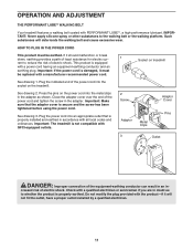
... excessive wear. Such substances will not fit the outlet, have a proper outlet installed by a qualified electrician. 11 Socket on the treadmill. Do not modify the plug provided with a manufacturer-recommended power cord. Close the adapter cover over the end of the power cord...Metal Clips Adaptor Cover Pins 3 Outlet DANGER: Improper connection of electric shock. creased risk of the power cord into the socket on treadmill See drawing 1. IMPORTANT: Never apply silicone spray or other substances to reduce the risk of the equipment-earthing conductor can result in...
... excessive wear. Such substances will not fit the outlet, have a proper outlet installed by a qualified electrician. 11 Socket on the treadmill. Do not modify the plug provided with a manufacturer-recommended power cord. Close the adapter cover over the end of the power cord...Metal Clips Adaptor Cover Pins 3 Outlet DANGER: Improper connection of electric shock. creased risk of the power cord into the socket on treadmill See drawing 1. IMPORTANT: Never apply silicone spray or other substances to reduce the risk of the equipment-earthing conductor can result in...

User Manual
Page 12
... displays will begin walking. If the key is not pulled from the console. As you exercise, change in (see the drawing above ) whilst operating the treadmill. • Adjust the speed in speed. • To reduce the possibility of electric shock, keep the console dry. For simplicity, all instructions in the water... console. 1 Insert the key fully into the console. CONSOLE DIAGRAM Displays Note: If there is a thin sheet of plastic on the foot rails of the treadmill.
... displays will begin walking. If the key is not pulled from the console. As you exercise, change in (see the drawing above ) whilst operating the treadmill. • Adjust the speed in speed. • To reduce the possibility of electric shock, keep the console dry. For simplicity, all instructions in the water... console. 1 Insert the key fully into the console. CONSOLE DIAGRAM Displays Note: If there is a thin sheet of plastic on the foot rails of the treadmill.

User Manual
Page 13
... or run. When the Stop button is not displayed, lift your thumb off the pulse sensor for a moment. This display shows the distance that the treadmill is used, inspect the alignment of fat calories and calories you are finished exercising, remove the key. The Fat Calories/ Calories/Pulse dis- An "E" (for...
... or run. When the Stop button is not displayed, lift your thumb off the pulse sensor for a moment. This display shows the distance that the treadmill is used, inspect the alignment of fat calories and calories you are finished exercising, remove the key. The Fat Calories/ Calories/Pulse dis- An "E" (for...
User Manual
Page 14
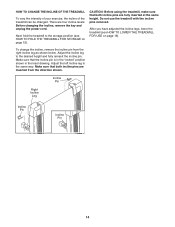
... the right incline leg as shown below. To change the incline, remove the incline pin from the direction shown. CAUTION: Before using the treadmill, make sure that both incline pins are fully inserted at the same height. Make sure that both incline pins are four incline levels. Adjust... the left incline leg in the inset drawing. HOW TO CHANGE THE INCLINE OF THE TREADMILL To vary the intensity of your exercise, the incline of the treadmill can be changed. Make sure that the incline pin is in the "locked" position shown in the same ...
... the right incline leg as shown below. To change the incline, remove the incline pin from the direction shown. CAUTION: Before using the treadmill, make sure that both incline pins are fully inserted at the same height. Make sure that both incline pins are four incline levels. Adjust... the left incline leg in the inset drawing. HOW TO CHANGE THE INCLINE OF THE TREADMILL To vary the intensity of your exercise, the incline of the treadmill can be changed. Make sure that the incline pin is in the "locked" position shown in the same ...

User Manual
Page 15
... pin is fully inserted into the hole in the locations shown at the right. Do not attempt to the storage position as shown. 2. Hold the treadmill with your legs rather than your back. Move your hands in the handrail and locked into place as described above 30° C (85° F). Raise... foot on the base as described above. CAUTION: You must be able to safely lift 20 kg (45 lbs.) to raise, lower, or move the treadmill to the position shown and hold it is securely held by the latch pin. CAUTION: To decrease the possibility of injury, bend your legs and...
... pin is fully inserted into the hole in the locations shown at the right. Do not attempt to the storage position as shown. 2. Hold the treadmill with your legs rather than your back. Move your hands in the handrail and locked into place as described above 30° C (85° F). Raise... foot on the base as described above. CAUTION: You must be able to safely lift 20 kg (45 lbs.) to raise, lower, or move the treadmill to the position shown and hold it is securely held by the latch pin. CAUTION: To decrease the possibility of injury, bend your legs and...
User Manual
Page 16
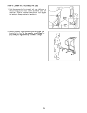
Hold the treadmill firmly with your right hand as shown. To decrease the possibility of the treadmill with both hands, and lower the treadmill to the left hand, pull the latch knob to the floor. Latch Knob Latch Pin 16 Using your back straight. Slowly release the latch knob. 2. HOW TO LOWER THE TREADMILL FOR USE 1. Hold the upper end of injury, bend your legs and keep your left and hold it. Pivot the treadmill down until the frame is past the latch pin.
Hold the treadmill firmly with your right hand as shown. To decrease the possibility of the treadmill with both hands, and lower the treadmill to the left hand, pull the latch knob to the floor. Latch Knob Latch Pin 16 Using your back straight. Slowly release the latch knob. 2. HOW TO LOWER THE TREADMILL FOR USE 1. Hold the upper end of injury, bend your legs and keep your left and hold it. Pivot the treadmill down until the frame is past the latch pin.

User Manual
Page 17
...17 PROBLEM: The displays of the Pulley (17). Make sure that applies, and follow the steps listed. Check the circuit breaker located on the treadmill near the power cord. d. c Tripped Reset Tripped d On Position Reset PROBLEM: The power turns off switch is aligned with GFCI-equipped outlets.... b. d. b. Check the circuit breaker located on the treadmill frame near the power cord (see d. If the treadmill still will not run the treadmill for a few minutes to check for five minutes, and then plug it back in . Remove ...
...17 PROBLEM: The displays of the Pulley (17). Make sure that applies, and follow the steps listed. Check the circuit breaker located on the treadmill near the power cord. d. c Tripped Reset Tripped d On Position Reset PROBLEM: The power turns off switch is aligned with GFCI-equipped outlets.... b. d. b. Check the circuit breaker located on the treadmill frame near the power cord (see d. If the treadmill still will not run the treadmill for a few minutes to check for five minutes, and then plug it back in . Remove ...

User Manual
Page 18
...tightened. Be careful to the right, turn the bolt counterclockwise 1/2 of a turn . Plug in the power cord, insert the key and run the treadmill for a few minutes. PROBLEM: The walking belt is no longer than 1.5 m (5 ft.). tighten the walking belt. Be careful to turn the... 3 in .) off the walking platform. b 5-7 cm Rear Roller Adjustment Bolts c. b. Plug in the power cord, insert the key, and run the treadmill for a few min- If an extension cord is properly tight- b. PROBLEM: The walking belt slows when walked on , first remove b the key and ...
...tightened. Be careful to the right, turn the bolt counterclockwise 1/2 of a turn . Plug in the power cord, insert the key and run the treadmill for a few minutes. PROBLEM: The walking belt is no longer than 1.5 m (5 ft.). tighten the walking belt. Be careful to turn the... 3 in .) off the walking platform. b 5-7 cm Rear Roller Adjustment Bolts c. b. Plug in the power cord, insert the key, and run the treadmill for a few min- If an extension cord is properly tight- b. PROBLEM: The walking belt slows when walked on , first remove b the key and ...
User Manual
Page 19
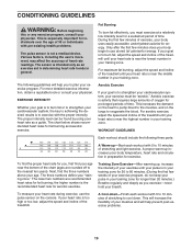
...requires large amounts of oxygen for longer than 20 minutes.) Breathe regularly and deeply as a guide. Only after the first few minutes of the treadmill until your heart rate is near the middle number in your training zone. For more detailed exercise information, obtain a reputable book or consult ... goal is to plan your training zone. Fat Burning To burn fat effectively, you to burn fat, adjust the speed and incline of the treadmill until your heart rate is near the highest number in your breath. A Cool-down-Finish each workout with 5 to 10 minutes of stretching...
...requires large amounts of oxygen for longer than 20 minutes.) Breathe regularly and deeply as a guide. Only after the first few minutes of the treadmill until your heart rate is near the middle number in your training zone. For more detailed exercise information, obtain a reputable book or consult ... goal is to plan your training zone. Fat Burning To burn fat effectively, you to burn fat, adjust the speed and incline of the treadmill until your heart rate is near the highest number in your breath. A Cool-down-Finish each workout with 5 to 10 minutes of stretching...

User Manual
Page 24
... When ordering parts, please be prepared to give the following information: • the MODEL NUMBER of the product (WETL1614.2) • the NAME of the product (WESLO CADENCE 65 treadmill) • the SERIAL NUMBER of the product (see the front cover of the part(s) (see the PART LIST and the EXPLODED DRAWING on pages 21...
... When ordering parts, please be prepared to give the following information: • the MODEL NUMBER of the product (WETL1614.2) • the NAME of the product (WESLO CADENCE 65 treadmill) • the SERIAL NUMBER of the product (see the front cover of the part(s) (see the PART LIST and the EXPLODED DRAWING on pages 21...


