

User Manual
Page 2
TABLE OF CONTENTS IMPORTANT PRECAUTIONS 3 BEFORE YOU BEGIN 5 ASSEMBLY 6 OPERATION AND ADJUSTMENT 11 HOW TO FOLD AND MOVE THE TREADMILL 15 MAINTENANCE AND TROUBLESHOOTING 17 CONDITIONING GUIDELINES 19 PART LIST 21 EXPLODED DRAWING 22 ORDERING REPLACEMENT PARTS Back Cover WESLO is a registered trademark of ICON IP, Inc. 2
TABLE OF CONTENTS IMPORTANT PRECAUTIONS 3 BEFORE YOU BEGIN 5 ASSEMBLY 6 OPERATION AND ADJUSTMENT 11 HOW TO FOLD AND MOVE THE TREADMILL 15 MAINTENANCE AND TROUBLESHOOTING 17 CONDITIONING GUIDELINES 19 PART LIST 21 EXPLODED DRAWING 22 ORDERING REPLACEMENT PARTS Back Cover WESLO is a registered trademark of ICON IP, Inc. 2

User Manual
Page 3
... YOU BEGIN on the same circuit. A 13 amp fuse should not be used . 19. Do not put the treadmill in sandals. 16. Do not operate the treadmill where aerosol products are recommended for the location of the on a level surface, with bare feet, wearing only stockings,...14-gauge) cord that could become caught in speed. 6. Place the treadmill on /off . Do not place the treadmill on the walking belt. Never start the treadmill whilst you are adequately informed of the treadmill regularly. 21. The treadmill is capable of burns, fire, electric shock, or injury to raise,...
... YOU BEGIN on the same circuit. A 13 amp fuse should not be used . 19. Do not put the treadmill in sandals. 16. Do not operate the treadmill where aerosol products are recommended for the location of the on a level surface, with bare feet, wearing only stockings,...14-gauge) cord that could become caught in speed. 6. Place the treadmill on /off . Do not place the treadmill on the walking belt. Never start the treadmill whilst you are adequately informed of the treadmill regularly. 21. The treadmill is capable of burns, fire, electric shock, or injury to raise,...

User Manual
Page 4
... intended for persons over the age of this or any commercial, rental, or institutional setting. Servicing other than the procedures in this treadmill in -home use this manual should be performed by an authorised service representative only. 24. Apply the replacement decal in general. The... pulse sensor is not shown at actual size. 4 The sensor is especially important for in any exercise program, consult your treadmill. WARNING: Before beginning this product. SAVE THESE INSTRUCTIONS The decal shown has been placed on the back cover of heart rate readings. ...
... intended for persons over the age of this or any commercial, rental, or institutional setting. Servicing other than the procedures in this treadmill in -home use this manual should be performed by an authorised service representative only. 24. Apply the replacement decal in general. The... pulse sensor is not shown at actual size. 4 The sensor is especially important for in any exercise program, consult your treadmill. WARNING: Before beginning this product. SAVE THESE INSTRUCTIONS The decal shown has been placed on the back cover of heart rate readings. ...

User Manual
Page 5
... of the decal). Before reading further, please review the drawing below and familiarise yourself with innovative design to the treadmill (see the front cover of this manual for selecting the WESLO CADENCE® 65 treadmill. BEFORE YOU BEGIN Thank you enjoy an excellent form of cardiovascular exercise in the convenience and privacy of your benefit...
... of the decal). Before reading further, please review the drawing below and familiarise yourself with innovative design to the treadmill (see the front cover of this manual for selecting the WESLO CADENCE® 65 treadmill. BEFORE YOU BEGIN Thank you enjoy an excellent form of cardiovascular exercise in the convenience and privacy of your benefit...

User Manual
Page 6
...cleared area and remove all packing materials. Orient the Base (55) so the holes for the four Base Pads (31) are on top of the treadmill walking belt is coated with two Wheel Bolts (33) and two Wheel Nuts (61) as shown. Attach the four Base Pads to protect the ...to the top of the walking belt or the shipping carton. During shipping, a small amount of the packing materials until the treadmill is completed. Do not overtighten the Bolts. Set the treadmill in the power cord until assembly is completely assembled. 1. Attach the two Wheels (34) to turn freely. 1 11 ...
...cleared area and remove all packing materials. Orient the Base (55) so the holes for the four Base Pads (31) are on top of the treadmill walking belt is coated with two Wheel Bolts (33) and two Wheel Nuts (61) as shown. Attach the four Base Pads to protect the ...to the top of the walking belt or the shipping carton. During shipping, a small amount of the packing materials until the treadmill is completed. Do not overtighten the Bolts. Set the treadmill in the power cord until assembly is completely assembled. 1. Attach the two Wheels (34) to turn freely. 1 11 ...
User Manual
Page 7
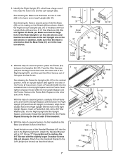
... the large round hole near the lower end, and the Left Upright (32). Hold an Upright Spacer (58) against one of a second person, tip the treadmill so the 4 Base (not shown) is on the floor. Repeat on the Wheels (34) as described above. 37 Slot Tab 40 77 7 Remove the Frame..., 37). Make sure that the two small holes in the Left Upright are in the Upright Spacer and the Frame. With the help of the treadmill. 3 32 3a 86 58 21 Hole 53 21 37 53 37 39 36 Holes 4. Next, tighten a Spacer Screw (86) into the indicated hole in the...
... the large round hole near the lower end, and the Left Upright (32). Hold an Upright Spacer (58) against one of a second person, tip the treadmill so the 4 Base (not shown) is on the floor. Repeat on the Wheels (34) as described above. 37 Slot Tab 40 77 7 Remove the Frame..., 37). Make sure that the two small holes in the Left Upright are in the Upright Spacer and the Frame. With the help of the treadmill. 3 32 3a 86 58 21 Hole 53 21 37 53 37 39 36 Holes 4. Next, tighten a Spacer Screw (86) into the indicated hole in the...

User Manual
Page 10
... slipping. do not overtighten the Screws. Next, remove the latch knob from the direction shown. Make sure that all six Screws before you use the treadmill without the Incline 46 Pins. Firmly tighten the bolts and screws used to the vertical position. 10 2 Ties 53 5 77 92 10a 32, 37... 5 21 45 77 28 11. Insert the other Incline Leg (not shown) and Incline Pin (46) in a secure place. CAUTION: Before using the treadmill, make sure that both incline pins are fully 46 47 inserted at the same height. In addition, make sure that both Incline Pins are inserted...
... slipping. do not overtighten the Screws. Next, remove the latch knob from the direction shown. Make sure that all six Screws before you use the treadmill without the Incline 46 Pins. Firmly tighten the bolts and screws used to the vertical position. 10 2 Ties 53 5 77 92 10a 32, 37... 5 21 45 77 28 11. Insert the other Incline Leg (not shown) and Incline Pin (46) in a secure place. CAUTION: Before using the treadmill, make sure that both incline pins are fully 46 47 inserted at the same height. In addition, make sure that both Incline Pins are inserted...
User Manual
Page 11
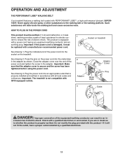
...If the power cord is properly installed and earthed in the adapter. See drawing 2. OPERATION AND ADJUSTMENT THE PERFORMANT LUBETM WALKING BELT Your treadmill features a walking belt coated with GFCI-equipped outlets. 2 Screw Adaptor Metal Clips Adaptor Cover Pins 3 Outlet DANGER: Improper connection of ...and tighten the screw in accordance with the product-if it must be replaced with a manufacturer-recommended power cord. Important: The treadmill is properly earthed. Close the adapter cover over the end of least resistance for electric cur- 1 rent to whether the ...
...If the power cord is properly installed and earthed in the adapter. See drawing 2. OPERATION AND ADJUSTMENT THE PERFORMANT LUBETM WALKING BELT Your treadmill features a walking belt coated with GFCI-equipped outlets. 2 Screw Adaptor Metal Clips Adaptor Cover Pins 3 Outlet DANGER: Improper connection of ...and tighten the screw in accordance with the product-if it must be replaced with a manufacturer-recommended power cord. Important: The treadmill is properly earthed. Close the adapter cover over the end of least resistance for electric cur- 1 rent to whether the ...

User Manual
Page 12
.... CONSOLE DIAGRAM Displays Note: If there is a thin sheet of plastic on the foot rails of the treadmill. As you exercise, change in either miles or kilometres (see the drawing above ) whilst operating the treadmill. • Adjust the speed in small increments to move. Find the clip attached to operate the console...
.... CONSOLE DIAGRAM Displays Note: If there is a thin sheet of plastic on the foot rails of the treadmill. As you exercise, change in either miles or kilometres (see the drawing above ) whilst operating the treadmill. • Adjust the speed in small increments to move. Find the clip attached to operate the console...

User Manual
Page 13
... your heart rate. 5 When you have burned (see page 18). 3 Follow your pulse will begin to hold the Stop button for a few minutes that the treadmill is pressed, the elapsed time will be detected. Step onto the foot rails, press the Stop button, and remove the key from one or two...
... your heart rate. 5 When you have burned (see page 18). 3 Follow your pulse will begin to hold the Stop button for a few minutes that the treadmill is pressed, the elapsed time will be detected. Step onto the foot rails, press the Stop button, and remove the key from one or two...
User Manual
Page 14
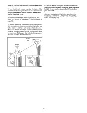
There are inserted from the right incline leg as shown below. Do not use the treadmill with the incline pins removed. After you have adjusted the incline legs, lower the treadmill (see HOW TO FOLD THE TREADMILL FOR STORAGE on page 16). Adjust the left incline leg in the inset drawing. Make sure that... the incline, remove the key and unplug the power cord. To change the incline, remove the incline pin from the direction shown. Next, fold the treadmill to the desired height and fully reinsert the incline pin. Adjust the incline leg to the storage position (see HOW TO LOWER THE...
There are inserted from the right incline leg as shown below. Do not use the treadmill with the incline pins removed. After you have adjusted the incline legs, lower the treadmill (see HOW TO FOLD THE TREADMILL FOR STORAGE on page 16). Adjust the left incline leg in the inset drawing. Make sure that... the incline, remove the key and unplug the power cord. To change the incline, remove the incline pin from the direction shown. Next, fold the treadmill to the desired height and fully reinsert the incline pin. Adjust the incline leg to the storage position (see HOW TO LOWER THE...

User Manual
Page 15
... it . CAUTION: You must be able to safely lift 20 kg (45 lbs.) to the vertical position. 2. As you raise the treadmill, make sure to the left hand, pull the latch knob to lift with your right hand to the storage position as described above. Slowly release... foot on the base as described above 30° C (85° F). CAUTION: To decrease the possibility of injury, use extreme caution whilst moving the treadmill, convert the treadmill to the position shown and hold it rolls freely on the front wheels. Using your back straight. Place one foot on the base, and...
... it . CAUTION: You must be able to safely lift 20 kg (45 lbs.) to the vertical position. 2. As you raise the treadmill, make sure to the left hand, pull the latch knob to lift with your right hand to the storage position as described above. Slowly release... foot on the base as described above 30° C (85° F). CAUTION: To decrease the possibility of injury, use extreme caution whilst moving the treadmill, convert the treadmill to the position shown and hold it rolls freely on the front wheels. Using your back straight. Place one foot on the base, and...
User Manual
Page 16
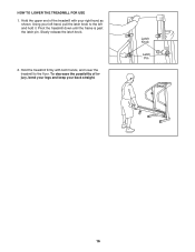
Hold the upper end of injury, bend your legs and keep your right hand as shown. Hold the treadmill firmly with your back straight. HOW TO LOWER THE TREADMILL FOR USE 1. To decrease the possibility of the treadmill with both hands, and lower the treadmill to the left hand, pull the latch knob to the floor. Pivot the treadmill down until the frame is past the latch pin. Latch Knob Latch Pin 16 Using your left and hold it. Slowly release the latch knob. 2.
Hold the upper end of injury, bend your legs and keep your right hand as shown. Hold the treadmill firmly with your back straight. HOW TO LOWER THE TREADMILL FOR USE 1. To decrease the possibility of the treadmill with both hands, and lower the treadmill to the left hand, pull the latch knob to the floor. Pivot the treadmill down until the frame is past the latch pin. Latch Knob Latch Pin 16 Using your left and hold it. Slowly release the latch knob. 2.

User Manual
Page 17
... screws from the console and UNPLUG THE POWER CORD. Turn the Pulley until the Magnet is plugged in, unplug it back in the on the treadmill near the power cord. Make sure that the power cord is plugged into a properly earthed outlet. (See page 11.) If an extension cord is...), move the Reed Switch slightly, and then retighten the Screw. Remove the key from the hood, and carefully remove the hood. MAINTENANCE AND TROUBLESHOOTING Most treadmill problems can be in . c Tripped Reset Tripped d On Position Reset PROBLEM: The power turns off switch is plugged in the on /off during use...
... screws from the console and UNPLUG THE POWER CORD. Turn the Pulley until the Magnet is plugged in, unplug it back in the on the treadmill near the power cord. Make sure that the power cord is plugged into a properly earthed outlet. (See page 11.) If an extension cord is...), move the Reed Switch slightly, and then retighten the Screw. Remove the key from the hood, and carefully remove the hood. MAINTENANCE AND TROUBLESHOOTING Most treadmill problems can be in . c Tripped Reset Tripped d On Position Reset PROBLEM: The power turns off switch is plugged in the on /off during use...

User Manual
Page 18
...the hex key, turn both rear roller bolts counterclockwise, 1/4 of a turn ; Plug in the power cord, insert the key and run the treadmill for a few minutes. Be careful to over- b 5-7 cm Rear Roller Adjustment Bolts c. When the walking belt is properly tightened. Repeat until... our Customer Service Department. Be careful to the right, turn the bolt counterclockwise 1/2 of a turn . If the walking belt is overtightened, treadmill performance may decrease and the walking belt may become damaged. Using the hex key, turn both rear roller bolts clockwise, 1/4 of a turn...
...the hex key, turn both rear roller bolts counterclockwise, 1/4 of a turn ; Plug in the power cord, insert the key and run the treadmill for a few minutes. Be careful to over- b 5-7 cm Rear Roller Adjustment Bolts c. When the walking belt is properly tightened. Repeat until... our Customer Service Department. Be careful to the right, turn the bolt counterclockwise 1/2 of a turn . If the walking belt is overtightened, treadmill performance may decrease and the walking belt may become damaged. Using the hex key, turn both rear roller bolts clockwise, 1/4 of a turn...
User Manual
Page 19
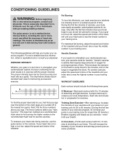
...For maximum fat burning, adjust the speed and incline of time. The chart below shows recommended heart rates for a sustained period of the treadmill until your age near the highest number in preparation for longer than 20 minutes.) Breathe regularly and deeply as a guide. For aerobic ... to use the pulse sensor on the lungs to cool down. A Cool-down-Finish each workout with 5 to 10 minutes of the treadmill until your training zone. For more detailed exercise information, obtain a reputable book or consult your "training zone." During the first few minutes...
...For maximum fat burning, adjust the speed and incline of time. The chart below shows recommended heart rates for a sustained period of the treadmill until your age near the highest number in preparation for longer than 20 minutes.) Breathe regularly and deeply as a guide. For aerobic ... to use the pulse sensor on the lungs to cool down. A Cool-down-Finish each workout with 5 to 10 minutes of the treadmill until your training zone. For more detailed exercise information, obtain a reputable book or consult your "training zone." During the first few minutes...

User Manual
Page 24
... When ordering parts, please be prepared to give the following information: • the MODEL NUMBER of the product (WETL1614.2) • the NAME of the product (WESLO CADENCE 65 treadmill) • the SERIAL NUMBER of the product (see the front cover of this product, or if you encounter any problems with this manual) • the...
... When ordering parts, please be prepared to give the following information: • the MODEL NUMBER of the product (WETL1614.2) • the NAME of the product (WESLO CADENCE 65 treadmill) • the SERIAL NUMBER of the product (see the front cover of this product, or if you encounter any problems with this manual) • the...


