
English Manual
Page 1
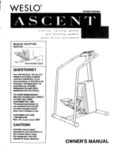
...-999-3756 Mon.-Fri., 6 a.m.-6 p.m. WESLO® PATENT PENDING ASCENT interval training system tt sel f - Serial Number Decal QUESTIONS? If you have questions, or find there are committed to you complete satisfaction through direct assistance from our factory. Carefully read all safety precautions and instructions in this manual before using this manual for future reference. OWNER'S MANUAL level ing pedals quiet dr ive resistance Model No.
...-999-3756 Mon.-Fri., 6 a.m.-6 p.m. WESLO® PATENT PENDING ASCENT interval training system tt sel f - Serial Number Decal QUESTIONS? If you have questions, or find there are committed to you complete satisfaction through direct assistance from our factory. Carefully read all safety precautions and instructions in this manual before using this manual for future reference. OWNER'S MANUAL level ing pedals quiet dr ive resistance Model No.
English Manual
Page 2
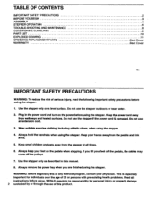
... TROUBLE-SHOOTING AND MAINTENANCE CONDITIONING GUIDELINES PART LIST EXPLODED DRAWING ORDERING REPLACEMENT PARTS WARRANTY 2 3 4 6 8 9 1 0 11 Back Cover Back Cover IMPORTANT SAFETY PRECAUTIONS WARNING: To reduce the risk of serious injury, read the following important safety precautions before using. Do not use an extension cord. 3. Always remove the power key when you lift your hands away from the pedals and link arms. 5. Do not use of this or any exercise program...
... TROUBLE-SHOOTING AND MAINTENANCE CONDITIONING GUIDELINES PART LIST EXPLODED DRAWING ORDERING REPLACEMENT PARTS WARRANTY 2 3 4 6 8 9 1 0 11 Back Cover Back Cover IMPORTANT SAFETY PRECAUTIONS WARNING: To reduce the risk of serious injury, read the following important safety precautions before using. Do not use an extension cord. 3. Always remove the power key when you lift your hands away from the pedals and link arms. 5. Do not use of this or any exercise program...
English Manual
Page 3
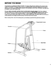
... be found on a decal attached to let you enjoy an effective form of low-impact cardiovascular exercise in just a few minutes a day. until 6 p.m. Programmable Console Handrails Frame Pedals Stabilizer Side Shield Stabilizer 3 For your home. The serial number can be healthier in the convenience of this manual carefully before calling. The ASCENT 775 stepper blends advanced engineering with quiet drive resistance and a programmable...
... be found on a decal attached to let you enjoy an effective form of low-impact cardiovascular exercise in just a few minutes a day. until 6 p.m. Programmable Console Handrails Frame Pedals Stabilizer Side Shield Stabilizer 3 For your home. The serial number can be healthier in the convenience of this manual carefully before calling. The ASCENT 775 stepper blends advanced engineering with quiet drive resistance and a programmable...
English Manual
Page 4
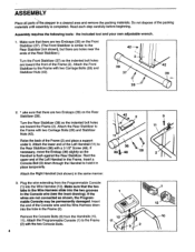
...Screw (48). Make sure that the two tabs in the Wire Harness slide into the two grooves in the Frame. Turn the Rear Stabilizer (38) so the indented bolt holes are not connected as shown, the Programmable Console may be permanently damaged. Attach the Right Handrail (not shown) in a cleared area and remove... bolt holes are two Endcaps (39) on the Rear Stabilizer (38). Attach the lower end of the Left Handrail in the Console wire (see the inset drawing). If necessary, move the Endcap (39) slightly so the Handrail is completed. Read each step carefully before beginning. Assembly ...
...Screw (48). Make sure that the two tabs in the Wire Harness slide into the two grooves in the Frame. Turn the Rear Stabilizer (38) so the indented bolt holes are not connected as shown, the Programmable Console may be permanently damaged. Attach the Right Handrail (not shown) in a cleared area and remove... bolt holes are two Endcaps (39) on the Rear Stabilizer (38). Attach the lower end of the Left Handrail in the Console wire (see the inset drawing). If necessary, move the Endcap (39) slightly so the Handrail is completed. Read each step carefully before beginning. Assembly ...
English Manual
Page 5
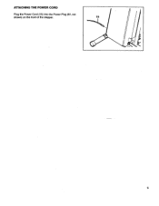
ATTACHING THE POWER CORD Plug the Power Cord (15) into the Power Plug (57, not shown) on the front of the stepper. 15 5
ATTACHING THE POWER CORD Plug the Power Cord (15) into the Power Plug (57, not shown) on the front of the stepper. 15 5
English Manual
Page 6
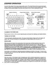
... step onto the pedals. Begin stepping, alternately pressing the right and left pedals down with continuous exercise feedback. PROGRAM MODE When the console is moved, it before operating the console. The stepping pace can exercise your back straight in order to reach the selected pace setting. The higher the control is off. teps Slow Mode Indicator Display Mode Program /Manual Power PLUGGING IN THE POWER CORD Plug the power cord into a 120-volt outlet. MANUAL MODE When the power is turned...
... step onto the pedals. Begin stepping, alternately pressing the right and left pedals down with continuous exercise feedback. PROGRAM MODE When the console is moved, it before operating the console. The stepping pace can exercise your back straight in order to reach the selected pace setting. The higher the control is off. teps Slow Mode Indicator Display Mode Program /Manual Power PLUGGING IN THE POWER CORD Plug the power cord into a 120-volt outlet. MANUAL MODE When the power is turned...
English Manual
Page 7
... exercise monitor. SCAN-Displays the STEPS PER MINUTE, TIME, TOTAL NO. To reset the LCD display, turn off the power. To start the program, press the program/manual button and begin again at least 8 inches as you are not used for five seconds each , in steps per minute. TIME-Displays the elapsed time. CALORIES-Displays the approximate number of the second program pace control. One mode indicator will automatically adjust to the manual mode by pressing...
... exercise monitor. SCAN-Displays the STEPS PER MINUTE, TIME, TOTAL NO. To reset the LCD display, turn off the power. To start the program, press the program/manual button and begin again at least 8 inches as you are not used for five seconds each , in steps per minute. TIME-Displays the elapsed time. CALORIES-Displays the approximate number of the second program pace control. One mode indicator will automatically adjust to the manual mode by pressing...
English Manual
Page 8
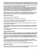
... Grease 51 ADJUSTING THE REED SWITCH IMPORTANT: For the exercise monitor to which the Link Arms (54) are too shallow, they will not be detected by the exercise monitor. 50 If the monitor still does not operate properly, the Reed Switch (56) should be adjusted. If your steps are attached should be oiled ever six months, or whenever the joints become noisy. Keep all parts of...
... Grease 51 ADJUSTING THE REED SWITCH IMPORTANT: For the exercise monitor to which the Link Arms (54) are too shallow, they will not be detected by the exercise monitor. 50 If the monitor still does not operate properly, the Reed Switch (56) should be adjusted. If your steps are attached should be oiled ever six months, or whenever the joints become noisy. Keep all parts of...
English Manual
Page 9
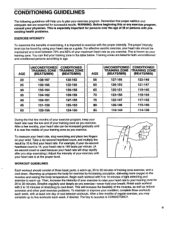
... exercise. This will help you exercise. After a few months, your heart rate can find your heart rate. WORKOUT GUIDELINES Each workout should be maintained at the proper level. Finish each week, with at least one day of rest between 70% and 85% of your exercise to raise your heart rate to your training zone for successful results. Warming up . O To measure your heart rate, stop exercising.) Adjust...
... exercise. This will help you exercise. After a few months, your heart rate can find your heart rate. WORKOUT GUIDELINES Each workout should be maintained at the proper level. Finish each week, with at least one day of rest between 70% and 85% of your exercise to raise your heart rate to your training zone for successful results. Warming up . O To measure your heart rate, stop exercising.) Adjust...
English Manual
Page 10
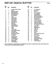
... 2 Pedal Arm Spacer 46 8 Pedal Arm Bushing 47 2 3/4" Pedal Arm Axle Cap 48 4 3 1/2" Screw 49 2 Pedal Arm 50 1 Magnet/Clamp 51 2 Clevis Pin 52 2 Cotter Pin 53 2 Bumper 54 2 Link Arm 55 2 Pedal 56 1 Reed Switch/Sensor Wire 67 1 Power Plug 58 2 Link Arm Axle 59 1 Pulley Axle 60 2 #10 Nylock Nut 61 1 Wire Harness Pigtail 62 2 Pedal Stop # 1 Owner's Manual Note: "#" indicates a non-illustrated part. PART LIST Model No. Qty. See the back cover for information about ordering replacement parts. 10 WLST77540 R894A Key...
... 2 Pedal Arm Spacer 46 8 Pedal Arm Bushing 47 2 3/4" Pedal Arm Axle Cap 48 4 3 1/2" Screw 49 2 Pedal Arm 50 1 Magnet/Clamp 51 2 Clevis Pin 52 2 Cotter Pin 53 2 Bumper 54 2 Link Arm 55 2 Pedal 56 1 Reed Switch/Sensor Wire 67 1 Power Plug 58 2 Link Arm Axle 59 1 Pulley Axle 60 2 #10 Nylock Nut 61 1 Wire Harness Pigtail 62 2 Pedal Stop # 1 Owner's Manual Note: "#" indicates a non-illustrated part. PART LIST Model No. Qty. See the back cover for information about ordering replacement parts. 10 WLST77540 R894A Key...
English Manual
Page 11
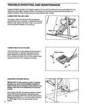
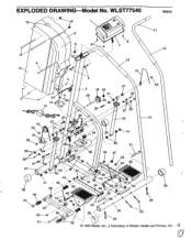
EXPLODED DRAWING Model No. WLST77540 • 16 6 R894A 11 3 4 4 17 • 8 6 8 7 13 12 1 13 19 5 9 2 18 25 59 21 5 6 14- 60 22 15 2 .••• 18 25 ... 54 48 42 39 46 48 52 19 47, 62 58 23 10 39 49 23--ar 51 39 38 28 48 46 © 1994 Weslo, Inc., a Subsidiary of Weider Health and Fitness, Inc. 11
EXPLODED DRAWING Model No. WLST77540 • 16 6 R894A 11 3 4 4 17 • 8 6 8 7 13 12 1 13 19 5 9 2 18 25 59 21 5 6 14- 60 22 15 2 .••• 18 25 ... 54 48 42 39 46 48 52 19 47, 62 58 23 10 39 49 23--ar 51 39 38 28 48 46 © 1994 Weslo, Inc., a Subsidiary of Weider Health and Fitness, Inc. 11
English Manual
Page 12
..., under this warranty is authorized by WESLO. The KEY NUMBER of this product to give the following information when calling: 1. until 6 p.m. Mountain Time (excluding holidays). The MODEL NUMBER of the product (WESLO® ASCENT 775 stepper). 3. LIMITED WARRANTY Weslo, Inc. ("WESLO"), warrants this manual. 5. This warranty extends only to replacing or repairing, at WESLO's option, the product at 1-800-999-3756, Monday through Friday, 6 a.m. WESLO's obligation under normal use and service conditions...
..., under this warranty is authorized by WESLO. The KEY NUMBER of this product to give the following information when calling: 1. until 6 p.m. Mountain Time (excluding holidays). The MODEL NUMBER of the product (WESLO® ASCENT 775 stepper). 3. LIMITED WARRANTY Weslo, Inc. ("WESLO"), warrants this manual. 5. This warranty extends only to replacing or repairing, at WESLO's option, the product at 1-800-999-3756, Monday through Friday, 6 a.m. WESLO's obligation under normal use and service conditions...


