

English Manual
Page 1
USERÕS MANUAL PATENT PENDING MST CAUTION Read all precautions and instructions in the space above for future reference. Model No. If you have questions, or if there are missing or damaged parts, we are committed to you. The trained technicians on our customer hot line will guarantee complete satisfaction through direct assistance from our factory. Save this equipment. CUSTOMER HOT LINE: 1-800-999-3756 Mon.ÐFri., 6 a.m.Ð6 p.m. Write the serial number in this manual before using this manual for future reference. TO AVOID UNNECESSARY DELAYS, PLEASE ...
USERÕS MANUAL PATENT PENDING MST CAUTION Read all precautions and instructions in the space above for future reference. Model No. If you have questions, or if there are missing or damaged parts, we are committed to you. The trained technicians on our customer hot line will guarantee complete satisfaction through direct assistance from our factory. Save this equipment. CUSTOMER HOT LINE: 1-800-999-3756 Mon.ÐFri., 6 a.m.Ð6 p.m. Write the serial number in this manual before using this manual for future reference. TO AVOID UNNECESSARY DELAYS, PLEASE ...

English Manual
Page 2
The weights will fall with pre-existing health problems. Read all instructions before using the leg press station, always make sure the cables are on the pulleys at all precautions. 2. Cover the floor or carpet beneath the gym system when performing an exercise home gym system for foot protection when exercising. 3. Replace any time while exercising, stop immediately and make sure the lock pin is intended for home use the home gym system in this product. 2 Make sure the cables remain on all instructions in a commercial, rental or institutional setting. 14....
The weights will fall with pre-existing health problems. Read all instructions before using the leg press station, always make sure the cables are on the pulleys at all precautions. 2. Cover the floor or carpet beneath the gym system when performing an exercise home gym system for foot protection when exercising. 3. Replace any time while exercising, stop immediately and make sure the lock pin is intended for home use the home gym system in this product. 2 Make sure the cables remain on all instructions in a commercial, rental or institutional setting. 14....
English Manual
Page 3
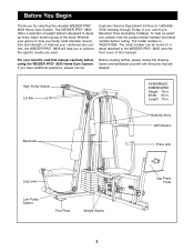
...note the product model number and serial number before using the WEIDER PRO¨ 9835 Home Gym System. To help you to the WEIDER PRO¨ 9835 (see the front cover of the body. The WEIDER PRO¨ 9835 offers a selection of weight stations designed to tone your body... Plate Width: 64 in . until 6 p.m. Length: 70 in . Whether your cardiovascular system, the WEIDER PRO¨ 9835 will help us assist you for selecting the versatile WEIDER PRO¨ 9835 Home Gym System. If you want. Customer Service Department toll-free at 1-800-9993756, Monday through Friday...
...note the product model number and serial number before using the WEIDER PRO¨ 9835 Home Gym System. To help you to the WEIDER PRO¨ 9835 (see the front cover of the body. The WEIDER PRO¨ 9835 offers a selection of weight stations designed to tone your body... Plate Width: 64 in . until 6 p.m. Length: 70 in . Whether your cardiovascular system, the WEIDER PRO¨ 9835 will help us assist you for selecting the versatile WEIDER PRO¨ 9835 Home Gym System. If you want. Customer Service Department toll-free at 1-800-9993756, Monday through Friday...

English Manual
Page 4
Assembly Note: This introduction will save you more convenient if you have a socket set, a set of open-end or closed-end wrenches or a set of evenings. Giving Yourself a Good Start Before you begin by deciding to make the task enjoyable, assembly will be attached to complete the process over a couple of ratchet wrenches. Note: Some small parts may want to the frame. Tightening of the packing materials until you begin the assembly process itself, take timeÑpossibly several hours. Do not dispose of Parts Tighten all parts as the skeleton of time, and by assembling the ...
Assembly Note: This introduction will save you more convenient if you have a socket set, a set of open-end or closed-end wrenches or a set of evenings. Giving Yourself a Good Start Before you begin by deciding to make the task enjoyable, assembly will be attached to complete the process over a couple of ratchet wrenches. Note: Some small parts may want to the frame. Tightening of the packing materials until you begin the assembly process itself, take timeÑpossibly several hours. Do not dispose of Parts Tighten all parts as the skeleton of time, and by assembling the ...

English Manual
Page 5
Insert four 5/16Ó x 2 1/2Ó Carriage Bolts (49) up through the Weight Base (14) and place it on the floor. Attach the Press Base (13) to the Weight Base. Frame Assembly 1. Do not tighten the Nylon Locknuts yet. Slide the Leg Press Upright (4) onto the indicated 5/16Ó x 2 1/2Ó Carriage Bolts (49) in the box above. Hand tighten two 5/16Ó Nylon Locknuts (40) onto the Carriage Bolts. Insert four 5/16Ó x 2 1/2Ó Carriage Bolts (49) up through the Press Base (13) and place it flat on the floor next to the Weight Base (14) with two 5/16Ó...
Insert four 5/16Ó x 2 1/2Ó Carriage Bolts (49) up through the Weight Base (14) and place it on the floor. Attach the Press Base (13) to the Weight Base. Frame Assembly 1. Do not tighten the Nylon Locknuts yet. Slide the Leg Press Upright (4) onto the indicated 5/16Ó x 2 1/2Ó Carriage Bolts (49) in the box above. Hand tighten two 5/16Ó Nylon Locknuts (40) onto the Carriage Bolts. Insert four 5/16Ó x 2 1/2Ó Carriage Bolts (49) up through the Press Base (13) and place it flat on the floor next to the Weight Base (14) with two 5/16Ó...

English Manual
Page 6
Press a 2Ó Square Inner Cap (56) into the top of the Butterfly Frame (3). Press two 1Ó Round Inner Caps (70) into each side of the Butterfly Frame. Insert a 5/16Ó x 2 3/4Ó Bolt (55) through the bracket on the side shown. Make sure that the Bolt is on the Butterfly Frame (3) and the Top Frame (2). Press a 2Ó Square Inner Cap (56) into the Front Seat Frame (8). 55 20 6 40 8 4 13 56 40 49 Make sure that the Bolt is on the Butterfly Frame (3) and the Top Frame (2). Slide the Front Seat Frame (8) onto the indicated 5/16Ó x 2 1/2Ó...
Press a 2Ó Square Inner Cap (56) into the top of the Butterfly Frame (3). Press two 1Ó Round Inner Caps (70) into each side of the Butterfly Frame. Insert a 5/16Ó x 2 3/4Ó Bolt (55) through the bracket on the side shown. Make sure that the Bolt is on the Butterfly Frame (3) and the Top Frame (2). Press a 2Ó Square Inner Cap (56) into the Front Seat Frame (8). 55 20 6 40 8 4 13 56 40 49 Make sure that the Bolt is on the Butterfly Frame (3) and the Top Frame (2). Slide the Front Seat Frame (8) onto the indicated 5/16Ó x 2 1/2Ó...

English Manual
Page 7
Press a Weight Tube Bumper (26) into each Weight 6 Tube (25). Insert a Weight Tube (25) into each stack of Weights (90). 5. Make sure the pin grooves are in the pin grooves in the upper Weights. 25 26 90 90 7 Make sure the pins on the Weight Tubes are on the Weight Base (14). 5 Slide a Weight Bumper (27) onto each of the Weight Guides (23). 90 Slide eight Weights (90) onto each stack of Weight Guides (23). Insert two Weight Guides (23) into each of the brackets on the indicated side of each set of Weights. 90 Pin Grooves 27 23 23 14 Pin Grooves 27 6.
Press a Weight Tube Bumper (26) into each Weight 6 Tube (25). Insert a Weight Tube (25) into each stack of Weights (90). 5. Make sure the pin grooves are in the pin grooves in the upper Weights. 25 26 90 90 7 Make sure the pins on the Weight Tubes are on the Weight Base (14). 5 Slide a Weight Bumper (27) onto each of the Weight Guides (23). 90 Slide eight Weights (90) onto each stack of Weight Guides (23). Insert two Weight Guides (23) into each of the brackets on the indicated side of each set of Weights. 90 Pin Grooves 27 23 23 14 Pin Grooves 27 6.

English Manual
Page 8
Lubricate the insides of the holes in the same manner. Slide a Top Weight onto each set of Weight Guides (23) in the Top Weights 7 (24) as shown. Attach the Top Frame (2) to the Top Frame (2) with two 5/16Ó x 2 3/4Ó Bolts (55), two 5/16Ó Washers (20) and two 5/16Ó Nylon Locknuts (40). Attach the upper ends of the other set of Weight Guides (23) to the Lat Upright (1) with two 5/16Ó x 2 3/4Ó Bolts (55), the Support Plate (98) and two 5/16Ó Nylon Locknuts (40). Attach the Butterfly Frame (3) to the bracket on the Top Frame (2) with a 5/16Ó x...
Lubricate the insides of the holes in the same manner. Slide a Top Weight onto each set of Weight Guides (23) in the Top Weights 7 (24) as shown. Attach the Top Frame (2) to the Top Frame (2) with two 5/16Ó x 2 3/4Ó Bolts (55), two 5/16Ó Washers (20) and two 5/16Ó Nylon Locknuts (40). Attach the upper ends of the other set of Weight Guides (23) to the Lat Upright (1) with two 5/16Ó x 2 3/4Ó Bolts (55), the Support Plate (98) and two 5/16Ó Nylon Locknuts (40). Attach the Butterfly Frame (3) to the bracket on the Top Frame (2) with a 5/16Ó x...

English Manual
Page 9
Lubricate the 3/8Ó x 3Ó Bolt (94). Slide the Press Frame onto the Press Base (13) so that the Plastic Bushings are aligned with the upper set of the 10 Leg Press Arm (9). 56 A 56 9 56 56 Arm Assembly 11 11. Note: This will be easy to the Press Base (13) with the 1Ó Tap Screw (72). Do not overtighten the Nylon Jamnut, it should be a tight fit. Make sure the Press Frame is oriented with the indicated tube. Lubricate the 3/8Ó x 8Ó Bolt (52). Attach the Press Frame (12) to pivot the Leg Press Arm. 8 9 53 72 13 43 94ÑLubricate 12. Locate ...
Lubricate the 3/8Ó x 3Ó Bolt (94). Slide the Press Frame onto the Press Base (13) so that the Plastic Bushings are aligned with the upper set of the 10 Leg Press Arm (9). 56 A 56 9 56 56 Arm Assembly 11 11. Note: This will be easy to the Press Base (13) with the 1Ó Tap Screw (72). Do not overtighten the Nylon Jamnut, it should be a tight fit. Make sure the Press Frame is oriented with the indicated tube. Lubricate the 3/8Ó x 8Ó Bolt (52). Attach the Press Frame (12) to pivot the Leg Press Arm. 8 9 53 72 13 43 94ÑLubricate 12. Locate ...

English Manual
Page 10
Press a 1 3/4Ó Square Inner Cap (48) 14 into the upper end of the Press 13 Frame (12) with the Right Arm (5). Press a 1 3/4Ó Square Inner Cap (48) into the Press Arm. Note: Be careful not to order new Retainers. The Retainers can be removed, you thoroughly understand the step. If they must be assembled only once. Make sure the teeth on the Retainers bend toward the Round Outer Cap, as shown in the same manner. 10 7 3 Bracket Lubricate Axle 45 48 46 6 Axle 45 46 Repeat this step, make sure you will need to confuse the Left Arm with two 5/16Ó...
Press a 1 3/4Ó Square Inner Cap (48) 14 into the upper end of the Press 13 Frame (12) with the Right Arm (5). Press a 1 3/4Ó Square Inner Cap (48) into the Press Arm. Note: Be careful not to order new Retainers. The Retainers can be removed, you thoroughly understand the step. If they must be assembled only once. Make sure the teeth on the Retainers bend toward the Round Outer Cap, as shown in the same manner. 10 7 3 Bracket Lubricate Axle 45 48 46 6 Axle 45 46 Repeat this step, make sure you will need to confuse the Left Arm with two 5/16Ó...

English Manual
Page 11
Slide a 10Ó Pad (45) onto the Left Arm. IMPORTANT: While assembling the cables, do not fully tighten it. Insert a 5/16Ó x 1Ó Bolt (95) through 47, refer to verify proper cable routing. The approximate length of this is listed after the key number in assembly step 55. 6 48 22 Cable Assembly 17 17. Find the Butterfly Cable (89)Ñthis manual to the CABLE DIAGRAMS on the Right Butterfly Arm (5). Repeat this section, fully unwind the five Cables and identify the Cables by comparing the lengths and the ends. 16. Locate and open the parts bags ...
Slide a 10Ó Pad (45) onto the Left Arm. IMPORTANT: While assembling the cables, do not fully tighten it. Insert a 5/16Ó x 1Ó Bolt (95) through 47, refer to verify proper cable routing. The approximate length of this is listed after the key number in assembly step 55. 6 48 22 Cable Assembly 17 17. Find the Butterfly Cable (89)Ñthis manual to the CABLE DIAGRAMS on the Right Butterfly Arm (5). Repeat this section, fully unwind the five Cables and identify the Cables by comparing the lengths and the ends. 16. Locate and open the parts bags ...

English Manual
Page 12
Wrap the Butterfly Cable (89) around a 3 1/2Ó Pulley (82) as shown. Refer to hold the Cable in the groove of the Pulley Plates (31) with two holes should be positioned to the inset drawing. Fully tighten a 91 5/16Ó Nylon Jam Nut (91) onto the Bolt. 89 Slide the free end of Pulley 20 Plates (31) and 3 1/2Ó Pulleys (82). The end of the Pulley. 80 50 42 89 82 4 22. Wrap the Butterfly Cable (89) around a 3 1/2Ó Pulley 19 (82) as shown. The Cable Trap must be oriented as shown and be down 21. 19. Attach the Pulley and a Cable ...
Wrap the Butterfly Cable (89) around a 3 1/2Ó Pulley (82) as shown. Refer to hold the Cable in the groove of the Pulley Plates (31) with two holes should be positioned to the inset drawing. Fully tighten a 91 5/16Ó Nylon Jam Nut (91) onto the Bolt. 89 Slide the free end of Pulley 20 Plates (31) and 3 1/2Ó Pulleys (82). The end of the Pulley. 80 50 42 89 82 4 22. Wrap the Butterfly Cable (89) around a 3 1/2Ó Pulley 19 (82) as shown. The Cable Trap must be oriented as shown and be down 21. 19. Attach the Pulley and a Cable ...

English Manual
Page 13
23. Attach a 3 1/2Ó Pulley (82) and a Cable Trap (80) to the Top Frame (2) with a 3/8Ó x 2Ó Bolt (50) and a 3/8Ó Nylon Locknut (42). Note: This may come pre-assembled. 24 87 Route the Rear Cable (87) through the Large ÒUÓ Bracket (84) and the 3 1/2Ó Pulley (82). Thread a 1/2Ó Plain Nut (35) onto the end of the Weight Tube (25) until the Weight Spacer (10) touches the Weight Tube. See the inset drawing. Attach the Pulley to the upper hole in a Large ÒUÓ Bracket (84) with a 3/8Ó x 2Ó 25 Bolt (50) and a 3/8Ó Nylon...
23. Attach a 3 1/2Ó Pulley (82) and a Cable Trap (80) to the Top Frame (2) with a 3/8Ó x 2Ó Bolt (50) and a 3/8Ó Nylon Locknut (42). Note: This may come pre-assembled. 24 87 Route the Rear Cable (87) through the Large ÒUÓ Bracket (84) and the 3 1/2Ó Pulley (82). Thread a 1/2Ó Plain Nut (35) onto the end of the Weight Tube (25) until the Weight Spacer (10) touches the Weight Tube. See the inset drawing. Attach the Pulley to the upper hole in a Large ÒUÓ Bracket (84) with a 3/8Ó x 2Ó 25 Bolt (50) and a 3/8Ó Nylon...

English Manual
Page 14
27. Attach the Pulley and a Cable Trap (80) to the other bracket on the Press Base (13) with a 3/8Ó x 2Ó Bolt (50) and a 3/8Ó Nylon Locknut (42). Find the Press Cable (88)Ñthis is turned to hold the Cable in place. 88 80 42 82 29. Wrap the Press Cable (88) around a 3 1/2Ó Pulley 29 (82). Make sure the Cable Trap is turned to hold the Cable in the inset drawing. 37 84 44 37 88 88 84 28. Do not completely tighten the Nylon Locknut. Attach the end of threads are 44 showing above the Nylon Locknut, as shown in place. 50 13 88 82 ...
27. Attach the Pulley and a Cable Trap (80) to the other bracket on the Press Base (13) with a 3/8Ó x 2Ó Bolt (50) and a 3/8Ó Nylon Locknut (42). Find the Press Cable (88)Ñthis is turned to hold the Cable in place. 88 80 42 82 29. Wrap the Press Cable (88) around a 3 1/2Ó Pulley 29 (82). Make sure the Cable Trap is turned to hold the Cable in the inset drawing. 37 84 44 37 88 88 84 28. Do not completely tighten the Nylon Locknut. Attach the end of threads are 44 showing above the Nylon Locknut, as shown in place. 50 13 88 82 ...

English Manual
Page 15
Refer to hold the Cable in place as shown in the inset drawing. Make 88 sure the Cable Trap is turned to hold the Cable in place. 32 38 94 88 33. Make sure the Cable Trap (80) is positioned to the inset drawing. Attach the Pulley and a Cable Trap (80) to the upper bracket on the Leg Press Upright (4) with a 3/8Ó x 3 1/2Ó Bolt (66), a 3/8Ó Washer (38) and a 3/8Ó Nylon Jam Nut (43). Make sure the Cable Trap (80) is between the Cable Trap (80) and the Pulley. Route the Press Cable (88) over the indicated 3 1/2Ó 30 Pulley (82) attached to...
Refer to hold the Cable in place as shown in the inset drawing. Make 88 sure the Cable Trap is turned to hold the Cable in place. 32 38 94 88 33. Make sure the Cable Trap (80) is positioned to the inset drawing. Attach the Pulley and a Cable Trap (80) to the upper bracket on the Leg Press Upright (4) with a 3/8Ó x 3 1/2Ó Bolt (66), a 3/8Ó Washer (38) and a 3/8Ó Nylon Jam Nut (43). Make sure the Cable Trap (80) is between the Cable Trap (80) and the Pulley. Route the Press Cable (88) over the indicated 3 1/2Ó 30 Pulley (82) attached to...

English Manual
Page 16
Attach the ÒVÓ Pulley to the lower bracket on the Leg 35 Press Upright (4) with a 3/8Ó x 2 1/2Ó Bolt (65) and a 3/8Ó Nylon Locknut (42). Hand tighten a 3/8Ó Nylon Jamnut (43) onto the Bolt. Attach the ÒVÓ Pulley and a Large Cable Trap (83) to the Press Frame (12) with the 3/8Ó x 4 1/2Ó Bolt (74). Attach the Pulley and a Cable Trap (80) to 37 the bracket on the Press Frame. 35. Wrap the Press Cable (88) around a 3 1/2Ó Pulley (82). Wrap the Press Cable (88) around a ÒVÓ Pulley (81). Attach the Pulley and a Cable ...
Attach the ÒVÓ Pulley to the lower bracket on the Leg 35 Press Upright (4) with a 3/8Ó x 2 1/2Ó Bolt (65) and a 3/8Ó Nylon Locknut (42). Hand tighten a 3/8Ó Nylon Jamnut (43) onto the Bolt. Attach the ÒVÓ Pulley and a Large Cable Trap (83) to the Press Frame (12) with the 3/8Ó x 4 1/2Ó Bolt (74). Attach the Pulley and a Cable Trap (80) to 37 the bracket on the Press Frame. 35. Wrap the Press Cable (88) around a 3 1/2Ó Pulley (82). Wrap the Press Cable (88) around a ÒVÓ Pulley (81). Attach the Pulley and a Cable ...

English Manual
Page 17
It is shown removed for the Cable to the Top Frame (2) with a 3/8Ó x 3 1/2Ó Bolt (66), a 3/8Ó Washer (38) and a 3/8Ó Nylon Jam Nut (43). Slide a 5/16Ó Washer (20) onto a 5/16Ó x 2 3/4Ó Bolt (55). Route the Press Cable (88) around a 3 1/2Ó Pulley (82). 41 Attach the Pulley and a Cable Trap (80) to pivot. 8 20 55 40. Leave enough room between the Pulley and the post. 40 38 42 Post 85 2 82 66 43 82 80 88 88 91 41. Note: The 3 1/2Ó Pulley (82) used in place and that the Cable Trap is positioned to the Top Frame (2) with the...
It is shown removed for the Cable to the Top Frame (2) with a 3/8Ó x 3 1/2Ó Bolt (66), a 3/8Ó Washer (38) and a 3/8Ó Nylon Jam Nut (43). Slide a 5/16Ó Washer (20) onto a 5/16Ó x 2 3/4Ó Bolt (55). Route the Press Cable (88) around a 3 1/2Ó Pulley (82). 41 Attach the Pulley and a Cable Trap (80) to pivot. 8 20 55 40. Leave enough room between the Pulley and the post. 40 38 42 Post 85 2 82 66 43 82 80 88 88 91 41. Note: The 3 1/2Ó Pulley (82) used in place and that the Cable Trap is positioned to the Top Frame (2) with the...

English Manual
Page 18
Refer to the Top Frame (2) with two holes should be routed from the direction shown. 2 50 82 85 44. Thread a 1/2Ó Plain Nut (35) onto the end of the Weight Tube (25) until the Weight Spacer (10) touches the Weight Tube. Attach the closed loop at the end of the Weight Tube (25). Thread the end of the Rear Cable (87) into the upper end of the High Cable (85). Make sure the flat side of the closed loop on the end of the Low Cable 45 (86) to the bracket on top of the Low Cable (86) is turned towards the bracket. 1 95 86 40 18 Tighten the 3/8Ó x 2Ó ...
Refer to the Top Frame (2) with two holes should be routed from the direction shown. 2 50 82 85 44. Thread a 1/2Ó Plain Nut (35) onto the end of the Weight Tube (25) until the Weight Spacer (10) touches the Weight Tube. Attach the closed loop at the end of the Weight Tube (25). Thread the end of the Rear Cable (87) into the upper end of the High Cable (85). Make sure the flat side of the closed loop on the end of the Low Cable 45 (86) to the bracket on top of the Low Cable (86) is turned towards the bracket. 1 95 86 40 18 Tighten the 3/8Ó x 2Ó ...

English Manual
Page 19
Make sure the Cable Trap is between the Pulley and the post. 86 1 43 38 82 66 Post 19 Remove the indicated 3/8Ó x 2Ó Bolt (50), the 3/8Ó Nylon Locknut (42), the 3 1/2Ó Pulley (82) and the 46 Cable Trap (80) from the indicated Pulley Plates (31). Wrap the Low Cable (86) around a 3 1/2Ó Pulley (82). The ball on the Cable must be on the indicated side of the Pulley. Lay the Low Cable (86) over the Pulley. Attach the Pulley to the Lat Upright (1) with the Bolt and the Nylon Locknut. Make sure the Cable and Pulley move smoothly and that the Cable is...
Make sure the Cable Trap is between the Pulley and the post. 86 1 43 38 82 66 Post 19 Remove the indicated 3/8Ó x 2Ó Bolt (50), the 3/8Ó Nylon Locknut (42), the 3 1/2Ó Pulley (82) and the 46 Cable Trap (80) from the indicated Pulley Plates (31). Wrap the Low Cable (86) around a 3 1/2Ó Pulley (82). The ball on the Cable must be on the indicated side of the Pulley. Lay the Low Cable (86) over the Pulley. Attach the Pulley to the Lat Upright (1) with the Bolt and the Nylon Locknut. Make sure the Cable and Pulley move smoothly and that the Cable is...

English Manual
Page 20
Press a 1 1/2Ó Square Inner Cap (57) into the Rear Seat Frame (16). 49 Insert a 1/4Ó x 2Ó Carriage Bolt (61) through the indicated hole in the Rear Seat Frame (16). Tighten a 1/4Ó Nylon Locknut (44) with a 1/4Ó Washer (37) onto the Carriage Bolt. 61 57 41 Attach the other end of the Seat (17) to the Rear Seat Frame (16) with a 5/16Ó Washer (20) onto the Eyebolt. 50 40 15 20 40 16 62ÑLubricate 79 57 51. Press a 1 1/2Ó Square Inner Cap (57) into the Leg Lever (15) from the direction shown. Lubricate the 5/16Ó x 2 1/4Ó Bolt (62). Do ...
Press a 1 1/2Ó Square Inner Cap (57) into the Rear Seat Frame (16). 49 Insert a 1/4Ó x 2Ó Carriage Bolt (61) through the indicated hole in the Rear Seat Frame (16). Tighten a 1/4Ó Nylon Locknut (44) with a 1/4Ó Washer (37) onto the Carriage Bolt. 61 57 41 Attach the other end of the Seat (17) to the Rear Seat Frame (16) with a 5/16Ó Washer (20) onto the Eyebolt. 50 40 15 20 40 16 62ÑLubricate 79 57 51. Press a 1 1/2Ó Square Inner Cap (57) into the Leg Lever (15) from the direction shown. Lubricate the 5/16Ó x 2 1/4Ó Bolt (62). Do ...