

English Manual
Page 9
... 5/16" Nylon Locknuts (40). Do not tighten the Nylon Locknuts yet. 12. Press a 2" Square Inner Cap (56) into the top of Weight Guides (23) in steps 2 through 12. 10 2 56 40 20 20 56 55 70 55 56 56 3 11 55 20 2 92 3 98 40 1 12 40 69 40 2 67 40...
... 5/16" Nylon Locknuts (40). Do not tighten the Nylon Locknuts yet. 12. Press a 2" Square Inner Cap (56) into the top of Weight Guides (23) in steps 2 through 12. 10 2 56 40 20 20 56 55 70 55 56 56 3 11 55 20 2 92 3 98 40 1 12 40 69 40 2 67 40...
English Manual
Page 11
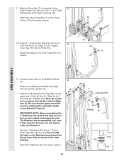
... two 5/16" Nylon Locknuts (40). Be sure that the upper end of 18 the Press Arms (7). The Retainers can be removed, you thoroughly understand the step. Be sure that you will need to order new Retainers. Press a 1 3/4" Square Inner Cap (48) into the Press Arm. Tap two 1" Retainers (45) and a ...1" Round Outer Cap (46) onto the axle. If they must be assembled only once. Attach the Right Arm (5) in this step for the other Press Arm (7) to one of the Left Arm is behind the indicated bracket on the Butterfly Frame (3). Slide the Left Arm onto...
... two 5/16" Nylon Locknuts (40). Be sure that the upper end of 18 the Press Arms (7). The Retainers can be removed, you thoroughly understand the step. Be sure that you will need to order new Retainers. Press a 1 3/4" Square Inner Cap (48) into the Press Arm. Tap two 1" Retainers (45) and a ...1" Round Outer Cap (46) onto the axle. If they must be assembled only once. Attach the Right Arm (5) in this step for the other Press Arm (7) to one of the Left Arm is behind the indicated bracket on the Butterfly Frame (3). Slide the Left Arm onto...

English Manual
Page 12
... Frame with the Bolt and a 3/8" Nylon Jam Nut (43). 12 48 30 16 96 99 48 15 43 30 65 72 95 48 Repeat this step with soapy water. 20.
... Frame with the Bolt and a 3/8" Nylon Jam Nut (43). 12 48 30 16 96 99 48 15 43 30 65 72 95 48 Repeat this step with soapy water. 20.

English Manual
Page 13
During steps 23 through the bracket on pages 30 and 31 of each Cable, in inches, is the 24 shortest Cable. The approximate length of this manual ...
During steps 23 through the bracket on pages 30 and 31 of each Cable, in inches, is the 24 shortest Cable. The approximate length of this manual ...

English Manual
Page 15
... post. Wrap the High Cable (86) around a 3 1/2" 30 Pulley (82). CABLE ASSEMBLY 29. Note: The 3 1/2" Pulley (82) in place. Locate the High Cable (86)-this step is shown removed for easier part identification. Tighten the 3/8" x 3 1/2" Bolt (66) and the 3/8" Nylon Locknut (42), with two holes should be downward. Route the High...
... post. Wrap the High Cable (86) around a 3 1/2" 30 Pulley (82). CABLE ASSEMBLY 29. Note: The 3 1/2" Pulley (82) in place. Locate the High Cable (86)-this step is shown removed for easier part identification. Tighten the 3/8" x 3 1/2" Bolt (66) and the 3/8" Nylon Locknut (42), with two holes should be downward. Route the High...

English Manual
Page 20
...) with a 1/4" Nylon Locknut (44) and a 1/4" Washer (37). Attach the end of the Pulley and that the Cable Trap (80) is turned as shown in this step is shown dis-assembled for easier part identification. It is 47 pre-assembled. Attach the Low Cable (89) to hold the Cable in the inset...
...) with a 1/4" Nylon Locknut (44) and a 1/4" Washer (37). Attach the end of the Pulley and that the Cable Trap (80) is turned as shown in this step is shown dis-assembled for easier part identification. It is 47 pre-assembled. Attach the Low Cable (89) to hold the Cable in the inset...

English Manual
Page 21
... that the Cable is in the groove of the Pulley and that the Cable Trap is turned as shown to hold the Cable in this step is shown dis-assembled for easier part identification. Route the Press Cable (88) over the indicated 3 1/2" Pulley (82) attached to the inset draw- Refer to...
... that the Cable is in the groove of the Pulley and that the Cable Trap is turned as shown to hold the Cable in this step is shown dis-assembled for easier part identification. Route the Press Cable (88) over the indicated 3 1/2" Pulley (82) attached to the inset draw- Refer to...

English Manual
Page 22
... the indicated hole in place and that the Cable Trap is between the Pulley and the cross- Do not fully tighten the Nylon Locknut until step 57. 55 88 74 82 80 82 43 80 9 22 bar on the Leg Press Upright (4) with a 3/8" x 2" Bolt (50) and a 3/8" Nylon Jam Nut (43). 50...
... the indicated hole in place and that the Cable Trap is between the Pulley and the cross- Do not fully tighten the Nylon Locknut until step 57. 55 88 74 82 80 82 43 80 9 22 bar on the Leg Press Upright (4) with a 3/8" x 2" Bolt (50) and a 3/8" Nylon Jam Nut (43). 50...

English Manual
Page 23
... attached in place and that the Cable is shown 57 removed for the Cable to hold the Cable in step 55. Slide a 5/16" Washer (20) onto a 5/16" x 2 3/4" 58 Bolt (55). Locate and open the parts bag labeled "SEAT ASSEMBLY." Insert the Bolt into the Front ...
... attached in place and that the Cable is shown 57 removed for the Cable to hold the Cable in step 55. Slide a 5/16" Washer (20) onto a 5/16" x 2 3/4" 58 Bolt (55). Locate and open the parts bag labeled "SEAT ASSEMBLY." Insert the Bolt into the Front ...

