
English Manual
Page 11
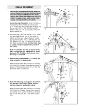
the pulleys must be necessary to turn freely. Note: To complete this step is turned to the CABLE DIAGRAMS and CABLE ID CHART on the Center Top Frame (14) with a... cable routing and help identifying the cables. Route the Cable up through the Left Top Frame (3). Attach the Pulley inside the Top Frame with a 3/8" x 2 3/4" Bolt (81), two 3/8" Washers (75), two 1/2" Spacers (34...45 66 11 IMPORTANT: While assembling the cables, do not over tighten the locknuts attaching the pulleys; Attach the Pulley to the single hole side of the bracket on pages 24 and 25 for clarity. Note...
the pulleys must be necessary to turn freely. Note: To complete this step is turned to the CABLE DIAGRAMS and CABLE ID CHART on the Center Top Frame (14) with a... cable routing and help identifying the cables. Route the Cable up through the Left Top Frame (3). Attach the Pulley inside the Top Frame with a 3/8" x 2 3/4" Bolt (81), two 3/8" Washers (75), two 1/2" Spacers (34...45 66 11 IMPORTANT: While assembling the cables, do not over tighten the locknuts attaching the pulleys; Attach the Pulley to the single hole side of the bracket on pages 24 and 25 for clarity. Note...
English Manual
Page 20
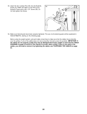
... have been properly tightened. If there is used. Attach the tether on pages 24 and 25 of the cables does not move smoothly over the pulleys. Do not fully tighten the Screw. 53 68 9 53 54. Before using the weight system, pull each cable a few times to make sure that all... remaining parts will need to the Butterfly Frame with a #8 x 3/4" Screw (68). See the CABLE DIAGRAM on the Pins to remove it by tightening the cables; IMPORTANT: If the cables are not properly routed, they may be explained in the cables...
... have been properly tightened. If there is used. Attach the tether on pages 24 and 25 of the cables does not move smoothly over the pulleys. Do not fully tighten the Screw. 53 68 9 53 54. Before using the weight system, pull each cable a few times to make sure that all... remaining parts will need to the Butterfly Frame with a #8 x 3/4" Screw (68). See the CABLE DIAGRAM on the Pins to remove it by tightening the cables; IMPORTANT: If the cables are not properly routed, they may be explained in the cables...


