
English Manual
Page 2
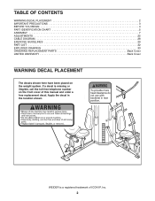
... is a registered trademark of this manual and order a free replacement decal. WEIDER is missing or illegible, call the toll-free telephone number on the weight system. TABLE OF CONTENTS WARNING DECAL PLACEMENT 2 IMPORTANT PRECAUTIONS 3 BEFORE YOU BEGIN 4 PART IDENTIFICATION CHART 5 ASSEMBLY 7 ADJUSTMENTS 25 CABLE DIAGRAM 28 EXERCISE GUIDELINES 29 PART LIST 32...
... is a registered trademark of this manual and order a free replacement decal. WEIDER is missing or illegible, call the toll-free telephone number on the weight system. TABLE OF CONTENTS WARNING DECAL PLACEMENT 2 IMPORTANT PRECAUTIONS 3 BEFORE YOU BEGIN 4 PART IDENTIFICATION CHART 5 ASSEMBLY 7 ADJUSTMENTS 25 CABLE DIAGRAM 28 EXERCISE GUIDELINES 29 PART LIST 32...
English Manual
Page 4
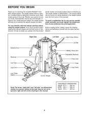
... offers a selection of weight stations designed to the weight system (see the front cover of this manual. To avoid a registration fee for selecting the versatile WEIDER® Club 4870 weight system. ASSEMBLED DIMENSIONS: Height: 81 in. / 206 cm Width: 82 in. / 208 cm Depth: 89 in the manual.
... offers a selection of weight stations designed to the weight system (see the front cover of this manual. To avoid a registration fee for selecting the versatile WEIDER® Club 4870 weight system. ASSEMBLED DIMENSIONS: Height: 81 in. / 206 cm Width: 82 in. / 208 cm Depth: 89 in the manual.
English Manual
Page 5
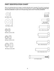
The number in parentheses by each drawing is not in assembly. Note: Some small parts may have been preattached. If a part is the key number of the part, from the PART LIST on page 6 to identify ...
The number in parentheses by each drawing is not in assembly. Note: Some small parts may have been preattached. If a part is the key number of the part, from the PART LIST on page 6 to identify ...
English Manual
Page 7
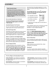
... of the packing materials until you begin by almost anyone. Make sure that there is designed to ensure that the weight system can be assembled successfully by assembling the base and the uprights that form the skeleton of open the parts package for each stage to open -end or closed-end wrenches..., or a set of the weight system. Important: Wait until assembly is not in the parts bag, check to see the front cover of soapy water, and clear tape or masking tape. Note: Some small parts...
... of the packing materials until you begin by almost anyone. Make sure that there is designed to ensure that the weight system can be assembled successfully by assembling the base and the uprights that form the skeleton of open the parts package for each stage to open -end or closed-end wrenches..., or a set of the weight system. Important: Wait until assembly is not in the parts bag, check to see the front cover of soapy water, and clear tape or masking tape. Note: Some small parts...
English Manual
Page 8
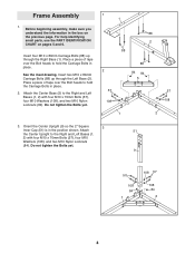
Before beginning assembly, make sure you understand the information in the position shown. Insert four M10 x 80mm Carriage Bolts (88) up through the Right Base (1). Insert two M10 x ... (108), and two M10 Nylon Locknuts (84). Orient the Center Upright (9) so the 2" Square 3 Inner Cap (51) is in the box on pages 5 and 6. Frame Assembly 1. Place a piece of tape over the Bolt heads to hold the Carriage Bolts in place. See the inset drawing. Attach 51 the Center Upright to...
Before beginning assembly, make sure you understand the information in the position shown. Insert four M10 x 80mm Carriage Bolts (88) up through the Right Base (1). Insert two M10 x ... (108), and two M10 Nylon Locknuts (84). Orient the Center Upright (9) so the 2" Square 3 Inner Cap (51) is in the box on pages 5 and 6. Frame Assembly 1. Place a piece of tape over the Bolt heads to hold the Carriage Bolts in place. See the inset drawing. Attach 51 the Center Upright to...
English Manual
Page 12
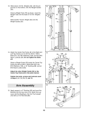
... Center Top Frame (6) in steps 3, 4, 7, 9, 10, 11, and 14. 14 84 108 84 6 68 57 87 108 108 3 68 87 57 108 4 30 30 Arm Assembly 15 15. Slide eleven 12.5-lb. Orient a Weight Tube (75) as shown.
... Center Top Frame (6) in steps 3, 4, 7, 9, 10, 11, and 14. 14 84 108 84 6 68 57 87 108 108 3 68 87 57 108 4 30 30 Arm Assembly 15 15. Slide eleven 12.5-lb. Orient a Weight Tube (75) as shown.
English Manual
Page 15
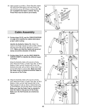
... a Pulley (43). Attach 23 the Leg Press Plate (29) to the Left Butterfly Arm (22) with the Bolt and an M10 Nylon Locknut (84). Cable Assembly 24 24. Attach the Pulley, a Cable Trap (48), an M10 Washer (108), and two Guards (45) to the Leg Press (12) with an M10 x 50mm...
... a Pulley (43). Attach 23 the Leg Press Plate (29) to the Left Butterfly Arm (22) with the Bolt and an M10 Nylon Locknut (84). Cable Assembly 24 24. Attach the Pulley, a Cable Trap (48), an M10 Washer (108), and two Guards (45) to the Leg Press (12) with an M10 x 50mm...
English Manual
Page 22
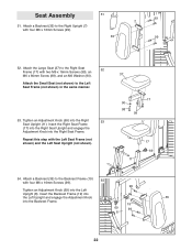
... M6 Washer (90). Attach a Backrest (35) to the Right Seat 52 Frame (17) with four M6 x 16mm Screws (99). 51 35 99 7 99 52. Seat Assembly 51. Insert the Backrest Frame (19) into the Left Upright and engage the Adjustment Knob 35 into the Right Seat Frame. Insert the Right Seat...
... M6 Washer (90). Attach a Backrest (35) to the Right Seat 52 Frame (17) with four M6 x 16mm Screws (99). 51 35 99 7 99 52. Seat Assembly 51. Insert the Backrest Frame (19) into the Left Upright and engage the Adjustment Knob 35 into the Right Seat Frame. Insert the Right Seat...
English Manual
Page 28
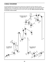
If the cables have been assembled correctly. CABLE DIAGRAM The cable diagrams below show the correct route for each cable. Make sure that the cables, the cable traps, and the guards ...
If the cables have been assembled correctly. CABLE DIAGRAM The cable diagrams below show the correct route for each cable. Make sure that the cables, the cable traps, and the guards ...


