
Assembly Instructions
Page 1
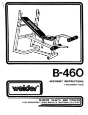
iri I1A1, • B-460 : MO ASSEMBLY INSTRUCTIONS • REPLACEMENT PARTS WEIDER HEALTH AND FITNESS) 21100 ERWIN STREET, WOODLAND HILLS, CALIFORNIA, U.S.A. 91367
iri I1A1, • B-460 : MO ASSEMBLY INSTRUCTIONS • REPLACEMENT PARTS WEIDER HEALTH AND FITNESS) 21100 ERWIN STREET, WOODLAND HILLS, CALIFORNIA, U.S.A. 91367
Assembly Instructions
Page 2
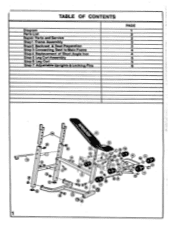
FA o M C - 7 ... . ° , 11 _ 0 9 -0 1" 3 - . J M ' rot 0 .. - 11 3 . • . 9 P .. 11 i 1 i , sct : , O - ,dot, - - - 9 I_O a CD ra-A . •/° 1-1 - • ' 10 - TABLE OF CONTENTS Diagram Parts List Repair Parts and Service Step1 Frame Assembly Step 2 Backrest & Seat Preparation Step 3 Connecting Seat to Main Frame Step 4 Replacement of Short Angle Iron Step 5 Leg Curl Assembly Step 6 Leg Curl Step 7 Adjustable Uprights & Locking Pins PAGE 1 2 2 3 3 4 4 5_ 5 6 • 14 O _ -1 0 12 0 •H 0 .
FA o M C - 7 ... . ° , 11 _ 0 9 -0 1" 3 - . J M ' rot 0 .. - 11 3 . • . 9 P .. 11 i 1 i , sct : , O - ,dot, - - - 9 I_O a CD ra-A . •/° 1-1 - • ' 10 - TABLE OF CONTENTS Diagram Parts List Repair Parts and Service Step1 Frame Assembly Step 2 Backrest & Seat Preparation Step 3 Connecting Seat to Main Frame Step 4 Replacement of Short Angle Iron Step 5 Leg Curl Assembly Step 6 Leg Curl Step 7 Adjustable Uprights & Locking Pins PAGE 1 2 2 3 3 4 4 5_ 5 6 • 14 O _ -1 0 12 0 •H 0 .

Assembly Instructions
Page 3
Align bolt holes on UPRIGHT (1). Remove 2 MACHINE SCREWS (R) from seat and remove 1 SHORT ANGLE IRON (12). Tighten all bolts. BACKREST AND SEAT PREPARATION Turn assembled backrest and seat over to the main frame. 3 This preparation must be done in order to connect the seat to expose work area. Insert 2 SQUARE PLASTIC CAPS (K) into base of MAIN FRAME (3) with HEX HEAD BOLT (A) and LOCK • NUT (B). STEP 2 - FRAME ASSEMBLY 0 2 Insert 2 SQUARE...
Align bolt holes on UPRIGHT (1). Remove 2 MACHINE SCREWS (R) from seat and remove 1 SHORT ANGLE IRON (12). Tighten all bolts. BACKREST AND SEAT PREPARATION Turn assembled backrest and seat over to the main frame. 3 This preparation must be done in order to connect the seat to expose work area. Insert 2 SQUARE PLASTIC CAPS (K) into base of MAIN FRAME (3) with HEX HEAD BOLT (A) and LOCK • NUT (B). STEP 2 - FRAME ASSEMBLY 0 2 Insert 2 SQUARE...
Assembly Instructions
Page 4
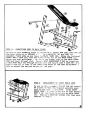
... were removed in Step 2. 4 Secure SEAT ADJUSTMENT :T (6) by inserting 1 HEX HEAD BOLT (E) through slot. EYELET PIN (G) is achieved. go. REPLACEMENT OF SHORT ANGLE IRON To aid in the remaining holes of the SEAT ADJUSTMENT T (6) to MAIN FRAME (3). Replace 2 MACHINE SCREWS (12) that the highest possible position of the seat is used in this assembly first slide BACKREST ADJUST BAR (15) into one of the seat. 0 0 15 0 0 a/. Align the SEAT ADJUSTMENT...
... were removed in Step 2. 4 Secure SEAT ADJUSTMENT :T (6) by inserting 1 HEX HEAD BOLT (E) through slot. EYELET PIN (G) is achieved. go. REPLACEMENT OF SHORT ANGLE IRON To aid in the remaining holes of the SEAT ADJUSTMENT T (6) to MAIN FRAME (3). Replace 2 MACHINE SCREWS (12) that the highest possible position of the seat is used in this assembly first slide BACKREST ADJUST BAR (15) into one of the seat. 0 0 15 0 0 a/. Align the SEAT ADJUSTMENT...
Assembly Instructions
Page 5
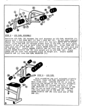
... on both sides of pad bar are on both sides. 8 11 III • • 7 0 0 0 0 0 9 O 9 0 © • .0 0 10 (r) • STEP 5 - Repeat the following instructions until all leg curl parts are in LEG H CURL ADJUSTER (7) until equal amounts of LEG CURL (8). Place COVER CAP (P) over tighten. LEG CURL • With assembled leg curl extended slightly forward, lower LEG CURL ADJUSTER (7) into weight pin on LEG CURL ADJUSTER (7). Slide FOAM PAD (10) onto...
... on both sides of pad bar are on both sides. 8 11 III • • 7 0 0 0 0 0 9 O 9 0 © • .0 0 10 (r) • STEP 5 - Repeat the following instructions until all leg curl parts are in LEG H CURL ADJUSTER (7) until equal amounts of LEG CURL (8). Place COVER CAP (P) over tighten. LEG CURL • With assembled leg curl extended slightly forward, lower LEG CURL ADJUSTER (7) into weight pin on LEG CURL ADJUSTER (7). Slide FOAM PAD (10) onto...
Assembly Instructions
Page 6
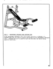
STEP 7 - ADJUSTABLE UPRIGHTS AND LOCKING PINS Slide ADJUSTABLE UPRIGHTS (14) into proper position in UPRIGHT (1). LOCKING PIN (J) is used to lock the LEG CURL (8) while doing specific exercises. 6 LOCKING PINS (H) are used to adjust the height of the ADJUSTABLE UPRIGHTS (14).
STEP 7 - ADJUSTABLE UPRIGHTS AND LOCKING PINS Slide ADJUSTABLE UPRIGHTS (14) into proper position in UPRIGHT (1). LOCKING PIN (J) is used to lock the LEG CURL (8) while doing specific exercises. 6 LOCKING PINS (H) are used to adjust the height of the ADJUSTABLE UPRIGHTS (14).


