

English Manual
Page 1
.... The trained technicians on our customer hot line will guarantee you complete satisfaction through direct assistance from our factory. CUSTOMER HOT NE: 1-800-667-2140 Mon.-Fri., 9 a.m. - 5 p.m. TO AVOID UNNECESSARY DELAYS, PLEASE CALL DIRECT TO OUR TOLL-FREE CUSTOMER HOT LINE. MULTI -STATION • PROFESSIONAL QUALITY FITNESS SYSTEM Model No. 2319 WG-8225 Serial No 0 OWNER'S MANUAL 0 Serial Number Decal (Under Seat) QUESTIONS...
.... The trained technicians on our customer hot line will guarantee you complete satisfaction through direct assistance from our factory. CUSTOMER HOT NE: 1-800-667-2140 Mon.-Fri., 9 a.m. - 5 p.m. TO AVOID UNNECESSARY DELAYS, PLEASE CALL DIRECT TO OUR TOLL-FREE CUSTOMER HOT LINE. MULTI -STATION • PROFESSIONAL QUALITY FITNESS SYSTEM Model No. 2319 WG-8225 Serial No 0 OWNER'S MANUAL 0 Serial Number Decal (Under Seat) QUESTIONS...

English Manual
Page 3
... or through the use . The feet of the person using the VKR arm could cause the hard drive system to cool before touching them. 13. If you use the lat bar. 12. Allow the resistance cylinders to tip. 11. TABLE OF CONTENTS IMPORTANT SAFETY PRECAUTIONS BEFORE YOU BEGIN ASSEMBLY ADJUSTMENT TROUBLE-SHOOTING AND MAINTENANCE CABLE DIAGRAM ORDERING REPLACEMENT PARTS LIMITED WARRANTY 3 4 5 15 18 19 Back Cover Back Cover IMPORTANT SAFETY PRECAUTIONS...
... or through the use . The feet of the person using the VKR arm could cause the hard drive system to cool before touching them. 13. If you use the lat bar. 12. Allow the resistance cylinders to tip. 11. TABLE OF CONTENTS IMPORTANT SAFETY PRECAUTIONS BEFORE YOU BEGIN ASSEMBLY ADJUSTMENT TROUBLE-SHOOTING AND MAINTENANCE CABLE DIAGRAM ORDERING REPLACEMENT PARTS LIMITED WARRANTY 3 4 5 15 18 19 Back Cover Back Cover IMPORTANT SAFETY PRECAUTIONS...

English Manual
Page 4
... the WEIDER 8225 (see the front cover of weight stations designed to let you want. To help you , please note the product model number and serial number before using the WEIDER 8225 Hard Drive System. ASSEMBLED DIMENSIONS Height: 77 inches (196 cm) Base: 64 inches x 64 inches (163 cm x 170 cm) VKR Handle O VKR Handle Knob Vertical Knee Raise (VKR) Arm Lat Bar High Pulley Station Selector Knob -Arms Resistance Cylinders Stepper Weight Stack Leg...
... the WEIDER 8225 (see the front cover of weight stations designed to let you want. To help you , please note the product model number and serial number before using the WEIDER 8225 Hard Drive System. ASSEMBLED DIMENSIONS Height: 77 inches (196 cm) Base: 64 inches x 64 inches (163 cm x 170 cm) VKR Handle O VKR Handle Knob Vertical Knee Raise (VKR) Arm Lat Bar High Pulley Station Selector Knob -Arms Resistance Cylinders Stepper Weight Stack Leg...

English Manual
Page 5
... (9) to each drawing carefully. Attach the Stabilizer (16) to the size and weight of the packing materials until assembly is on the Weight Tube (108). Place all nuts and bolts as shown in a cleared area and remove the packing materials. As you attach them, unless instructed to the PART IDENTIFICATION CHART accompanying this owner's manual. Grease and a small bowl of the Rear Upright (17) with two...
... (9) to each drawing carefully. Attach the Stabilizer (16) to the size and weight of the packing materials until assembly is on the Weight Tube (108). Place all nuts and bolts as shown in a cleared area and remove the packing materials. As you attach them, unless instructed to the PART IDENTIFICATION CHART accompanying this owner's manual. Grease and a small bowl of the Rear Upright (17) with two...

English Manual
Page 6
... the Rear Upright (17). Insert the Upright Brackets (84) between the Front Upright (19) and upper end of the Weight Cable (70) down into the Rear Upright (17). Tighten the 1/4" Nut (46) about halfway up the threaded end of the Rear Upright as the slot. Insert the Bolt Into the Weight Tube and tighten it into the Weight Tube (108). Each Weight must be turned so the "Weider...
... the Rear Upright (17). Insert the Upright Brackets (84) between the Front Upright (19) and upper end of the Weight Cable (70) down into the Rear Upright (17). Tighten the 1/4" Nut (46) about halfway up the threaded end of the Rear Upright as the slot. Insert the Bolt Into the Weight Tube and tighten it into the Weight Tube (108). Each Weight must be turned so the "Weider...

English Manual
Page 7
... " 62 44 45 061 62 19 • 7. 5. Insert the Bolt through the Front Upright, the VKR Frame and the Pivot Arm. Attach the VKR Frame Stop (44) to the Rear Upright (17) with the 5/16" x 3/4" Screw (129) and a 5/16" Flat Washer (45). 5 17 45 129...Arm (75) as shown. Align the hole in the bracket with 1/2" Tap Screws (127). Do not tighten the Nylock Nuts yet. Slide the 3/8" Flat Washer (64) and one 5/8" x 5/16" Spacer (121) onto the 3/8" x 2 3/4" Bolt (55). Attach the Front Upright (19) to the VKR Frame Stop (44) with the hole in assembly step 11. 7 Remove the Bolt...
... " 62 44 45 061 62 19 • 7. 5. Insert the Bolt through the Front Upright, the VKR Frame and the Pivot Arm. Attach the VKR Frame Stop (44) to the Rear Upright (17) with the 5/16" x 3/4" Screw (129) and a 5/16" Flat Washer (45). 5 17 45 129...Arm (75) as shown. Align the hole in the bracket with 1/2" Tap Screws (127). Do not tighten the Nylock Nuts yet. Slide the 3/8" Flat Washer (64) and one 5/8" x 5/16" Spacer (121) onto the 3/8" x 2 3/4" Bolt (55). Attach the Front Upright (19) to the VKR Frame Stop (44) with the hole in assembly step 11. 7 Remove the Bolt...

English Manual
Page 8
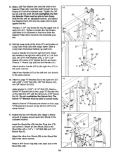
... manual. 10. Attach a VKR Armrest (80) to the VKR Frame (79) in the same manner. Press a 1" Round Cap (43) into the indicated end of the VKR Frame (79). Slide a VKR Handle (18) into the VKR Frame (79). Refer to the Rear Upright (17) with a 5/16" x 2" Carriage Bolt (130), 1/2" x 3/8" Spacer (57), 5/16" Flat Washer (45) and 5/16" Knob...
... manual. 10. Attach a VKR Armrest (80) to the VKR Frame (79) in the same manner. Press a 1" Round Cap (43) into the indicated end of the VKR Frame (79). Slide a VKR Handle (18) into the VKR Frame (79). Refer to the Rear Upright (17) with a 5/16" x 2" Carriage Bolt (130), 1/2" x 3/8" Spacer (57), 5/16" Flat Washer (45) and 5/16" Knob...

English Manual
Page 9
... tighten the Nuts yet. The upper end of the Arm must bend toward the Plastic Cap. Attach the Stepper Upright Extension (87) to upper axle on the retainers must be turned so the brackets are facing away from the Front Upright. Apply grease to the Front Upright ...Bolt (55), while sliding the Stepper Upright (97) onto the two indicated 5/16" x 2 1/2" Carriage Bolts (1) in assembly steps 2 through 5 (including this assembly step). 11 87 45 120 63 120 97 4 19 55 14 45 16 1 12. Tap the Retainers and Plastic Cap onto the axle. 11. Slide and Arm (27) onto the right axle. Press...
... tighten the Nuts yet. The upper end of the Arm must bend toward the Plastic Cap. Attach the Stepper Upright Extension (87) to upper axle on the retainers must be turned so the brackets are facing away from the Front Upright. Apply grease to the Front Upright ...Bolt (55), while sliding the Stepper Upright (97) onto the two indicated 5/16" x 2 1/2" Carriage Bolts (1) in assembly steps 2 through 5 (including this assembly step). 11 87 45 120 63 120 97 4 19 55 14 45 16 1 12. Tap the Retainers and Plastic Cap onto the axle. 11. Slide and Arm (27) onto the right axle. Press...
English Manual
Page 10
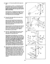
... 1/4" Nylock Nut (5). Attach a Large "U"-Bracket (53) to the Shock Bar with a 3/8" x 2 3/4" Bolt (55), 3/8" Flat Washer (64) and 3/8" Nylock Nut (63). Slide a 3/8" Flat Washer (64) onto the shaft of grease around each Arm (27). Do not overtighten the Nut; the Selector Plate must be able to swivel freely. Thread a 1 1/4" Tap Screw (8) into the right Arm (27). Tighten or loosen...
... 1/4" Nylock Nut (5). Attach a Large "U"-Bracket (53) to the Shock Bar with a 3/8" x 2 3/4" Bolt (55), 3/8" Flat Washer (64) and 3/8" Nylock Nut (63). Slide a 3/8" Flat Washer (64) onto the shaft of grease around each Arm (27). Do not overtighten the Nut; the Selector Plate must be able to swivel freely. Thread a 1 1/4" Tap Screw (8) into the right Arm (27). Tighten or loosen...

English Manual
Page 11
... Upright (19). Align one of the three sets of holes in the Adjustment Bracket (22) with the indicated hole in the same manner. 91 Attach the Small "U"-Bracket (21) to the Seat Brackets (39) with a 5/16" x 1. 3/4" Bolt (52) and 5/16" Nylock Nut (4). If the Arm Shock will not extend far enough, it is as short as possible. Press...
... Upright (19). Align one of the three sets of holes in the Adjustment Bracket (22) with the indicated hole in the same manner. 91 Attach the Small "U"-Bracket (21) to the Seat Brackets (39) with a 5/16" x 1. 3/4" Bolt (52) and 5/16" Nylock Nut (4). If the Arm Shock will not extend far enough, it is as short as possible. Press...
English Manual
Page 12
...; Apply grease to the pedal axles on the Seat Frame (32) with a 1/2" Tap Screw (127). Do not overtighten the Nylock Nut; Insert the other Pad Tube into the Leg Lever (33). Tighten a 5/16" Knob (11) onto the Bolt. 24. Press two 1 3/8" Bushings (90) into the ends of the Pedals, as shown. Slide a 5/8" Spacer (106) and a Resistance Cylinder (99) onto each Pedal (100...
...; Apply grease to the pedal axles on the Seat Frame (32) with a 1/2" Tap Screw (127). Do not overtighten the Nylock Nut; Insert the other Pad Tube into the Leg Lever (33). Tighten a 5/16" Knob (11) onto the Bolt. 24. Press two 1 3/8" Bushings (90) into the ends of the Pedals, as shown. Slide a 5/8" Spacer (106) and a Resistance Cylinder (99) onto each Pedal (100...

English Manual
Page 14
... cables are properly tightened. Remove the decals from the Decal Sheet (not shown), and apply them to make sure that all remaining parts will be damaged when heavy weight is used. 14 If one of this owner's manual. 31. tions shown in the loca. Pull each cable. WEIDER 8225 SQUAT/MILITARY HIGH PULLEY VKR STEPPER BENCH PRESS/ BUTTERFLY COMBINATION e LOW PULLEY 0 A 0 LEG EXTENSION 30. Before using the hard drive...
... cables are properly tightened. Remove the decals from the Decal Sheet (not shown), and apply them to make sure that all remaining parts will be damaged when heavy weight is used. 14 If one of this owner's manual. 31. tions shown in the loca. Pull each cable. WEIDER 8225 SQUAT/MILITARY HIGH PULLEY VKR STEPPER BENCH PRESS/ BUTTERFLY COMBINATION e LOW PULLEY 0 A 0 LEG EXTENSION 30. Before using the hard drive...

English Manual
Page 15
... BENCH PRESS exercise, convert the Arms to the cables and pulleys, the actual amount of resistance at each exercise station may od vary from 12.5 pounds to see how the hard drive system should be changed by turning the Selector Knob counterclockwise. 15 99 101 97 100 • 27 IMPORTANT: When attaching the lat bar or nylon strap, make sure that the hooks are in the correct starting...
... BENCH PRESS exercise, convert the Arms to the cables and pulleys, the actual amount of resistance at each exercise station may od vary from 12.5 pounds to see how the hard drive system should be changed by turning the Selector Knob counterclockwise. 15 99 101 97 100 • 27 IMPORTANT: When attaching the lat bar or nylon strap, make sure that the hooks are in the correct starting...
English Manual
Page 16
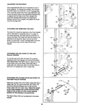
... Front Upright. Adjust the length of the three holes in assembly step 21 on page 11. The Nylon Strap (125) can be attached to the Front Upright (19) (see ATTACHING AND REMOVING THE SEAT above). ATTACHING THE LEG LEVER TO THE LOW PULLEY STATION To use the Leg Lever (33), the Seat (31) must be attached between the Lat Bar and the Pulley Cable so the Lat Bar is not attached to the leg lever. Attach...
... Front Upright. Adjust the length of the three holes in assembly step 21 on page 11. The Nylon Strap (125) can be attached to the Front Upright (19) (see ATTACHING AND REMOVING THE SEAT above). ATTACHING THE LEG LEVER TO THE LOW PULLEY STATION To use the Leg Lever (33), the Seat (31) must be attached between the Lat Bar and the Pulley Cable so the Lat Bar is not attached to the leg lever. Attach...
English Manual
Page 17
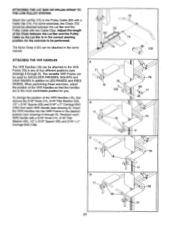
... used for you. To change the position of the VKR Handles so that the handles are in the most comfortable position for SHOULDER PRESSES, SQUATS and CALF RAISES in any of the Chain between the Lat Bar and the Pulley Cable with a Cable Clip (74). When performing these exercises, adjust the position of the VKR Handles (18), first remove the 5/16" Knob...
... used for you. To change the position of the VKR Handles so that the handles are in the most comfortable position for SHOULDER PRESSES, SQUATS and CALF RAISES in any of the Chain between the Lat Bar and the Pulley Cable with a Cable Clip (74). When performing these exercises, adjust the position of the VKR Handles (18), first remove the 5/16" Knob...

English Manual
Page 18
... the Pulley Cable. Retighten 123 0 the adjustment screw. If there is any worn parts immediately. Tighten the 1/4" Nut (46) farther 56 108 e--46 onto the end of this owner's manual for information about ordering replacement parts. Insert the Cable Bracket back onto the Weight Tube. Adjustment Screw 0 69 Adjustment Ball Sleeve 18 Do not use the hard drive system. Remove the Cable Bracket (56) from the Weight Tube (108). If the weight cable or pulley cable need...
... the Pulley Cable. Retighten 123 0 the adjustment screw. If there is any worn parts immediately. Tighten the 1/4" Nut (46) farther 56 108 e--46 onto the end of this owner's manual for information about ordering replacement parts. Insert the Cable Bracket back onto the Weight Tube. Adjustment Screw 0 69 Adjustment Ball Sleeve 18 Do not use the hard drive system. Remove the Cable Bracket (56) from the Weight Tube (108). If the weight cable or pulley cable need...
English Manual
Page 19
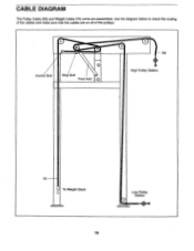
CABLE DIAGRAM The Pulley Cable (69) and Weight Cable (70) come pre-assembled. Use the diagram below to check the routing of the cables and make sure that the cables are on all of the pulleys. 0 0 0 0 69 Anchor Bolt Stop Bolt 0 Pivot Arm High Pulley Station 70 To Weight Stack Low Pulley Station 60.- 19
CABLE DIAGRAM The Pulley Cable (69) and Weight Cable (70) come pre-assembled. Use the diagram below to check the routing of the cables and make sure that the cables are on all of the pulleys. 0 0 0 0 69 Anchor Bolt Stop Bolt 0 Pivot Arm High Pulley Station 70 To Weight Stack Low Pulley Station 60.- 19

English Manual
Page 20
Eastern Time (excluding holidays). The MODEL NUMBER of the product (WEIDER® 8225 Hard Drive System). 3. No other warranty beyond that specifically set forth above is made must be free from defects in Canada WEIDER IS NOT RESPONSIBLE OR LIABLE FOR INDIRECT, SPECIAL OR CONSEQUENTIAL DAMAGES ARISING OUT OF OR IN CONNECTION WITH THE USE OR PERFORMANCE OF THE PRODUCT OR OTHER DAMAGES WITH...
Eastern Time (excluding holidays). The MODEL NUMBER of the product (WEIDER® 8225 Hard Drive System). 3. No other warranty beyond that specifically set forth above is made must be free from defects in Canada WEIDER IS NOT RESPONSIBLE OR LIABLE FOR INDIRECT, SPECIAL OR CONSEQUENTIAL DAMAGES ARISING OUT OF OR IN CONNECTION WITH THE USE OR PERFORMANCE OF THE PRODUCT OR OTHER DAMAGES WITH...

English Manual
Page 21
IMPORTANT CUSTOMER NOTICE WEIMER SPORTING GOOOS MODEL S225 ASSEMBLY INSTRUCTION UPDATES DEAR CUSTOMER, PLEASE REFER TO THE FOLLOWING INSTRUCTIONS DURING ASSEMBLY STEP 6. ATTACH THE VKR FRAME STOP (44) TO THE FRONT UPRIGHT (19) YOU MUST BOLT THROUGH THE HOLE WHICH IS CLOSER TO THE REAR UPRIGHT, AND DO NOT USE THE UPPER FLAT WASHER (45) JUST LIKE ON THE ILLUSTRATION BELOW. 127 128 7 61 u 62 44 eitN•61 • 62- 1 19 I • 150994 MG/SS-8225A
IMPORTANT CUSTOMER NOTICE WEIMER SPORTING GOOOS MODEL S225 ASSEMBLY INSTRUCTION UPDATES DEAR CUSTOMER, PLEASE REFER TO THE FOLLOWING INSTRUCTIONS DURING ASSEMBLY STEP 6. ATTACH THE VKR FRAME STOP (44) TO THE FRONT UPRIGHT (19) YOU MUST BOLT THROUGH THE HOLE WHICH IS CLOSER TO THE REAR UPRIGHT, AND DO NOT USE THE UPPER FLAT WASHER (45) JUST LIKE ON THE ILLUSTRATION BELOW. 127 128 7 61 u 62 44 eitN•61 • 62- 1 19 I • 150994 MG/SS-8225A

English Manual
Page 22
... Screw (89)-2 A 1 1/4" Tap Screw (8)-4 \\\\\\\\\\\\ 5/16" x 1 3/4" Screw (114)-1 1/4" x 2" Screw (82)-4 See the opposite side of the part. The number in parenthesis below each part refers of the key number of this chart for all of the nuts, washers, screws and bolts used in assembly. The second number refers to help you identify the small parts used in assembly. WG82250 R994A This chart is provided to the quantity used in assembly. PART IDENTIFICATION CHART Model No...
... Screw (89)-2 A 1 1/4" Tap Screw (8)-4 \\\\\\\\\\\\ 5/16" x 1 3/4" Screw (114)-1 1/4" x 2" Screw (82)-4 See the opposite side of the part. The number in parenthesis below each part refers of the key number of this chart for all of the nuts, washers, screws and bolts used in assembly. The second number refers to help you identify the small parts used in assembly. WG82250 R994A This chart is provided to the quantity used in assembly. PART IDENTIFICATION CHART Model No...


