
English Manual
Page 1
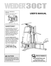
... precautions and instructions in the space above for future reference. The trained technicians on our customer hot line will guarantee you complete satisfaction through direct assistance from our factory. CUSTOMER HOT LINE: 1-800-999-3756 Mon.-Fri., 6 a.m.-6 p.m. USER'S MANUAL Visit our website at www.weiderfitness.com new products, prizes, fitness tips, and much more! Serial Number Decal (Under Seat) QUESTIONS...
... precautions and instructions in the space above for future reference. The trained technicians on our customer hot line will guarantee you complete satisfaction through direct assistance from our factory. CUSTOMER HOT LINE: 1-800-999-3756 Mon.-Fri., 6 a.m.-6 p.m. USER'S MANUAL Visit our website at www.weiderfitness.com new products, prizes, fitness tips, and much more! Serial Number Decal (Under Seat) QUESTIONS...
English Manual
Page 2
TABLE OF CONTENTS IMPORTANT PRECAUTIONS 3 BEFORE YOU BEGIN 4 ASSEMBLY 5 ADJUSTMENTS 21 WEIGHT RESISTANCE CHART 23 TROUBLE-SHOOTING AND MAINTENANCE 24 CABLE DIAGRAMS 25 ORDERING REPLACEMENT PARTS Back Cover LIMITED WARRANTY Back Cover Note: A PART IDENTIFICATION CHART and a PART LIST/EXPLODED DRAWING are attached to the center of ICON Health & Fitness, Inc. 2 WEIDER is a registered trademark of this manual. Remove the PART IDENTIFICATION CHART and the PART LIST/EXPLODED DRAWING before beginning assembly.
TABLE OF CONTENTS IMPORTANT PRECAUTIONS 3 BEFORE YOU BEGIN 4 ASSEMBLY 5 ADJUSTMENTS 21 WEIGHT RESISTANCE CHART 23 TROUBLE-SHOOTING AND MAINTENANCE 24 CABLE DIAGRAMS 25 ORDERING REPLACEMENT PARTS Back Cover LIMITED WARRANTY Back Cover Note: A PART IDENTIFICATION CHART and a PART LIST/EXPLODED DRAWING are attached to the center of ICON Health & Fitness, Inc. 2 WEIDER is a registered trademark of this manual. Remove the PART IDENTIFICATION CHART and the PART LIST/EXPLODED DRAWING before beginning assembly.
English Manual
Page 3
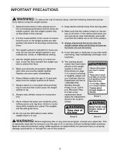
... Customer Service Department toll-free at any exercise program, consult your physician. Keep hands and feet away from the weight system at all warnings and precautions. 3. If a decal is intended for foot protection. 9. Mountain Time, to protect the floor. 5. Never release the press arm, butterfly arms, military press arm, leg lever, lat bar or nylon strap while weights are on a level surface. Do not use of...
... Customer Service Department toll-free at any exercise program, consult your physician. Keep hands and feet away from the weight system at all warnings and precautions. 3. If a decal is intended for foot protection. 9. Mountain Time, to protect the floor. 5. Never release the press arm, butterfly arms, military press arm, leg lever, lat bar or nylon strap while weights are on a level surface. Do not use of...
English Manual
Page 4
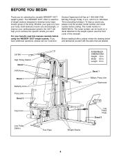
Lat Bar High Pulley Station Decal 1 VKR Arms Decal 1 Butterfly Arms Press Arm Decal 3 Leg Lever Low Pulley Station Foot Plate ASSEMBLED DIMENSIONS: Height: 76 in . The WEIDER® 30CT offers a selection of weight stations designed to tone your body, build dramatic muscle size and strength, or improve your cardiovascular system, the 30CT will help us assist you for selecting the versatile WEIDER® 30CT weight system. until 6 p.m. The model number is to...
Lat Bar High Pulley Station Decal 1 VKR Arms Decal 1 Butterfly Arms Press Arm Decal 3 Leg Lever Low Pulley Station Foot Plate ASSEMBLED DIMENSIONS: Height: 76 in . The WEIDER® 30CT offers a selection of weight stations designed to tone your body, build dramatic muscle size and strength, or improve your cardiovascular system, the 30CT will help us assist you for selecting the versatile WEIDER® 30CT weight system. until 6 p.m. The model number is to...
English Manual
Page 5
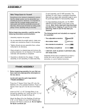
... find that the weight system can be assembled successfully by setting aside plenty of open the parts bag labeled "FRAME ASSEMBLY." Before beginning assembly, carefully read and understand the information in the center of ratchet wrenches. Wait until assembly is completed. • Assembly is not in the indicated locations. Press a 2" Square Inner Cap (27) into five stages: 1) frame assembly, 2) arm assembly, 3) cable assembly, 4) seat assembly, and 5) VKR assembly. Attach the Base...
... find that the weight system can be assembled successfully by setting aside plenty of open the parts bag labeled "FRAME ASSEMBLY." Before beginning assembly, carefully read and understand the information in the center of ratchet wrenches. Wait until assembly is completed. • Assembly is not in the indicated locations. Press a 2" Square Inner Cap (27) into five stages: 1) frame assembly, 2) arm assembly, 3) cable assembly, 4) seat assembly, and 5) VKR assembly. Attach the Base...

English Manual
Page 6
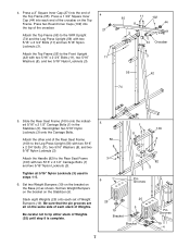
2. Attach the Rubber Bumper (91) to the Leg Press Upright (56) with the #8 x 1/2" Self-tapping Screw (87). 27 87 91 74 3 3 3 1 3. Press a 2" Square Inner Cap (27) into the Front Upright (42). 3 Slide the Front Upright (42) onto the 5/16" x 2 1/2" Carriage Bolts (1) in the Stabilizer (5). Handtighten a 5/16" Nylon Locknut (3) onto each Carriage Bolt. Do not tighten the Nylon Locknuts yet. 27 High Sides...
2. Attach the Rubber Bumper (91) to the Leg Press Upright (56) with the #8 x 1/2" Self-tapping Screw (87). 27 87 91 74 3 3 3 1 3. Press a 2" Square Inner Cap (27) into the Front Upright (42). 3 Slide the Front Upright (42) onto the 5/16" x 2 1/2" Carriage Bolts (1) in the Stabilizer (5). Handtighten a 5/16" Nylon Locknut (3) onto each Carriage Bolt. Do not tighten the Nylon Locknuts yet. 27 High Sides...
English Manual
Page 7
...-tighten two 5/16" Nylon Locknuts (3) onto the Carriage Bolts. Slide the Rear Seat Frame (100) onto the indicated 5/16" x 2 1/2" Carriage Bolts (1) in steps 1-5. 6. Set two Weight Bumpers on the bracket on the Base (4) as shown. Be sure that the pin grooves are all 5/16" Nylon Locknuts (3) used in the Stabilizer (5). Attach the Handle (82) to the VKR Upright (74) and the Leg Press Upright (56...
...-tighten two 5/16" Nylon Locknuts (3) onto the Carriage Bolts. Slide the Rear Seat Frame (100) onto the indicated 5/16" x 2 1/2" Carriage Bolts (1) in steps 1-5. 6. Set two Weight Bumpers on the bracket on the Base (4) as shown. Be sure that the pin grooves are all 5/16" Nylon Locknuts (3) used in the Stabilizer (5). Attach the Handle (82) to the VKR Upright (74) and the Leg Press Upright (56...
English Manual
Page 9
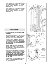
... Nylon Locknut; Attach the Leg Press Plate to the Top Frame (55) with the Press Pin (97). 11. Slide the Press Frame into the ends of holes in the Leg Press Arm (96). Make sure that the pulleys are on the Press Frame (17). Lubricate the 3/8" x 8" Bolt (59). Locate and open the parts bag labeled "ARM ASSEMBLY." Press a 1" x 7/8" Plastic Bushing (90) onto each side of the Long Weight Guides (62) to...
... Nylon Locknut; Attach the Leg Press Plate to the Top Frame (55) with the Press Pin (97). 11. Slide the Press Frame into the ends of holes in the Leg Press Arm (96). Make sure that the pulleys are on the Press Frame (17). Lubricate the 3/8" x 8" Bolt (59). Locate and open the parts bag labeled "ARM ASSEMBLY." Press a 1" x 7/8" Plastic Bushing (90) onto each side of the Long Weight Guides (62) to...

English Manual
Page 10
... step 13 to the Right Arm (48) with the Left Arm (47); Be sure that the upper end of the Right Arm is very important for step 14. Attach a "V"-Pulley (50) and a Long Cable Trap (31) to identify the Right Arm. Press two...Cover Cap, as shown in the same manner. Wet the lower end of each Arm with two 5/16" x 2 1/2" Bolts (22) and two 5/16" Nylon Locknuts (3). 22 Assemble the other Press Arm (46) in the same manner. 48 14. Arm identification is behind the indicated bracket on the Top Frame (55). Press a 1 3/4" Square Inner Cap (44) into the Press Arm. 44 49 Attach...
... step 13 to the Right Arm (48) with the Left Arm (47); Be sure that the upper end of the Right Arm is very important for step 14. Attach a "V"-Pulley (50) and a Long Cable Trap (31) to identify the Right Arm. Press two...Cover Cap, as shown in the same manner. Wet the lower end of each Arm with two 5/16" x 2 1/2" Bolts (22) and two 5/16" Nylon Locknuts (3). 22 Assemble the other Press Arm (46) in the same manner. 48 14. Arm identification is behind the indicated bracket on the Top Frame (55). Press a 1 3/4" Square Inner Cap (44) into the Press Arm. 44 49 Attach...

English Manual
Page 11
.... Attach the Military Press Arm (84) to turn freely. 17. During steps 16 through 36, refer to the CABLE DIAGRAMS on the indicated side of the Military Press Arm (84). Press two 1" Round Inner Caps (49) into the indicated end of the Pulley, and that the Cable is listed (in inches) after the key number in the drawing. 15. Attach the Pulley to verify proper cable routing. Attach the Military Press Arm...
.... Attach the Military Press Arm (84) to turn freely. 17. During steps 16 through 36, refer to the CABLE DIAGRAMS on the indicated side of the Military Press Arm (84). Press two 1" Round Inner Caps (49) into the indicated end of the Pulley, and that the Cable is listed (in inches) after the key number in the drawing. 15. Attach the Pulley to verify proper cable routing. Attach the Military Press Arm...

English Manual
Page 17
... Pulley move smoothly. Locate the Leg Press Cable (99). Do not completely tighten the Nylon Locknut; The ball on the Cable must be room between the Cable Trap (66) and the 3 1/2" Pulley (15). 34. Insert the Bolt through the Pivot Arm (101) from the indicated side. Slide the end of the Military Press Cable (72) onto the end of the Cable to the Leg Press Upright (56) with a 3/8" x 2" Bolt...
... Pulley move smoothly. Locate the Leg Press Cable (99). Do not completely tighten the Nylon Locknut; The ball on the Cable must be room between the Cable Trap (66) and the 3 1/2" Pulley (15). 34. Insert the Bolt through the Pivot Arm (101) from the indicated side. Slide the end of the Military Press Cable (72) onto the end of the Cable to the Leg Press Upright (56) with a 3/8" x 2" Bolt...

English Manual
Page 18
... of the Rear Backrest (85) to the Rear Seat Frame (100) with a 1/4" Washer (10) onto the Carriage Bolt. Attach one end of the Seat to the Leg Press 36 Arm (96) with a 1/4" x 2 1/2" Screw (43) and a 1/4" Washer (10). 38. Insert the Bolt through the center hole in the Leg Press Upright (56). 36. Wrap the Leg Press Cable (99) around a 3 1/2" Pulley (15). Slide the end of the Leg Press Cable (99) onto...
... of the Rear Backrest (85) to the Rear Seat Frame (100) with a 1/4" Washer (10) onto the Carriage Bolt. Attach one end of the Seat to the Leg Press 36 Arm (96) with a 1/4" x 2 1/2" Screw (43) and a 1/4" Washer (10). 38. Insert the Bolt through the center hole in the Leg Press Upright (56). 36. Wrap the Leg Press Cable (99) around a 3 1/2" Pulley (15). Slide the end of the Leg Press Cable (99) onto...

English Manual
Page 19
... the Leg Lever (29) from the direction shown. Tighten a 1/4" Nylon Locknut (2) with a 5/16" x 2 3/4" Carriage Bolt (14) and the Seat Knob (40). 42 43 10 41 Thick End 13 38 37 18 32 36 81 10 2 33 35 32 36 3 29 8 3 42 40 14 36 Pin 19 Attach the Front Seat Frame to the Front Seat Frame (36) with two 1/4" x 3/4" Screws (18...
... the Leg Lever (29) from the direction shown. Tighten a 1/4" Nylon Locknut (2) with a 5/16" x 2 3/4" Carriage Bolt (14) and the Seat Knob (40). 42 43 10 41 Thick End 13 38 37 18 32 36 81 10 2 33 35 32 36 3 29 8 3 42 40 14 36 Pin 19 Attach the Front Seat Frame to the Front Seat Frame (36) with two 1/4" x 3/4" Screws (18...
English Manual
Page 20
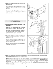
... CABLE DIAGRAMS on pages 25 and 26 of the Pad Tube. Press two 3/4" Round Inner Caps (34) into the Front Seat Frame (36). See TROUBLE-SHOOTING AND MAINTENANCE on page 21 of the Left and Right VKR Arms (79, 80). 43. Attach a VKR Armrest (78) to the VKR Upright (74) with two 1/4" x 2" Machine Screws (81) and two 1/4" Washers (10). Before using the weight...
... CABLE DIAGRAMS on pages 25 and 26 of the Pad Tube. Press two 3/4" Round Inner Caps (34) into the Front Seat Frame (36). See TROUBLE-SHOOTING AND MAINTENANCE on page 21 of the Left and Right VKR Arms (79, 80). 43. Attach a VKR Armrest (78) to the VKR Upright (74) with two 1/4" x 2" Machine Screws (81) and two 1/4" Washers (10). Before using the weight...
English Manual
Page 21
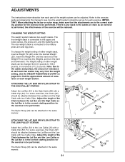
... lower pulleys, the press arm, and the butterfly arms. The rear weight stack is in the correct starting position for each exercise station may vary from 6.5 pounds to the military press arm and leg press. ATTACHING THE LAT BAR OR NYLON STRAP TO THE HIGH PULLEY STATION Attach the Lat Bar (54) to be performed. Adjust the length of the Chain between the Lat Bar and the High Cable with two Cable Clips. IMPORTANT: When attaching the lat bar...
... lower pulleys, the press arm, and the butterfly arms. The rear weight stack is in the correct starting position for each exercise station may vary from 6.5 pounds to the military press arm and leg press. ATTACHING THE LAT BAR OR NYLON STRAP TO THE HIGH PULLEY STATION Attach the Lat Bar (54) to be performed. Adjust the length of the Chain between the Lat Bar and the High Cable with two Cable Clips. IMPORTANT: When attaching the lat bar...

English Manual
Page 22
...) from the Leg Press Plate (95) and the Leg Press Arm (96). Re-insert the Press Pin (97) through the welded tubes on Leg Press Plate and the holes in the Leg Press Arm (96). ADJUSTING THE LEG PRESS PLATE Remove the Press Pin (97) from the Front Seat Frame (36). Lift the Front Seat Frame off the Front Upright (42). ATTACHING THE LEG LEVER TO THE LOW PULLEY STATION To use the Leg Lever (29...
...) from the Leg Press Plate (95) and the Leg Press Arm (96). Re-insert the Press Pin (97) through the welded tubes on Leg Press Plate and the holes in the Leg Press Arm (96). ADJUSTING THE LEG PRESS PLATE Remove the Press Pin (97) from the Front Seat Frame (36). Lift the Front Seat Frame off the Front Upright (42). ATTACHING THE LEG LEVER TO THE LOW PULLEY STATION To use the Leg Lever (29...
English Manual
Page 23
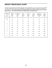
.... The butterfly arm resistance listed is the resistance for each butterfly arm. top weight. The other numbers refer to the 6.5 lb. WEIGHT RESISTANCE CHART This chart shows the approximate weight resistance at each weight station may vary due to differences in individual weight plates, as well as friction between the cables, pulleys, and weight guides. WEIGHT PLATES PRESS ARM (lbs.) BUTTERFLY ARM (lbs.) LEG LEVER (lbs.) HIGH PULLEY (lbs.) LOW PULLEY (lbs.) MILITARY PRESS ARM (lbs.) LEG PRESS (lbs.) Top...
.... The butterfly arm resistance listed is the resistance for each butterfly arm. top weight. The other numbers refer to the 6.5 lb. WEIGHT RESISTANCE CHART This chart shows the approximate weight resistance at each weight station may vary due to differences in individual weight plates, as well as friction between the cables, pulleys, and weight guides. WEIGHT PLATES PRESS ARM (lbs.) BUTTERFLY ARM (lbs.) LEG LEVER (lbs.) HIGH PULLEY (lbs.) LOW PULLEY (lbs.) MILITARY PRESS ARM (lbs.) LEG PRESS (lbs.) Top...
English Manual
Page 24
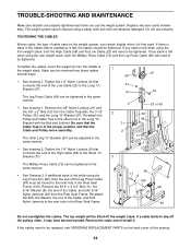
... use solvents. Tighten the 1/4" Nylon Locknut (2) that the Cable Trap is in the cables before resistance is first used on the back cover of the Leg Press Cable (99) must be moved to the next hole in the same manner. • See drawing 1. Remove the 3/8" Nylon Locknut (21) and the 3/8" x 2" Bolt (12) from the Rear Seat Frame. Re-attach the Pulley and Cable Trap to be cleaned using the rear weight...
... use solvents. Tighten the 1/4" Nylon Locknut (2) that the Cable Trap is in the cables before resistance is first used on the back cover of the Leg Press Cable (99) must be moved to the next hole in the same manner. • See drawing 1. Remove the 3/8" Nylon Locknut (21) and the 3/8" x 2" Bolt (12) from the Rear Seat Frame. Re-attach the Pulley and Cable Trap to be cleaned using the rear weight...
English Manual
Page 30
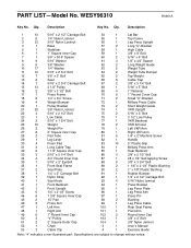
... Grip 84 1 Military Press Arm 85 1 Rear Backrest 86 3 3/8" x 2 1/2" Bolt 87 1 #8 x 1/2" Self-tapping Screw 88 5 3/8" x 3 3/4" Bolt 89 2 1 1/8" x 2 1/2" Plastic Bushing 90 2 1" x 7/8" Plastic Bushing 91 1 Rubber Bumper 92 1 1/4" x 2 1/2" Carriage Bolt 93 4 5/16" Nylon Jamnut 94 1 Press Bracket 95 1 Leg Press Plate 96 1 Leg Press Arm 97 1 Press Pin 98 2 Bushing 99 1 Leg Press Cable 100 1 Rear Seat Frame 101 1 Pivot Arm 102 2 Round Inner Cap 103 1 3/8" x 3" Bolt 104 1 3/8" Nylon Jamnut # 1 User's Manual # 1 Exercise Guide Note...
... Grip 84 1 Military Press Arm 85 1 Rear Backrest 86 3 3/8" x 2 1/2" Bolt 87 1 #8 x 1/2" Self-tapping Screw 88 5 3/8" x 3 3/4" Bolt 89 2 1 1/8" x 2 1/2" Plastic Bushing 90 2 1" x 7/8" Plastic Bushing 91 1 Rubber Bumper 92 1 1/4" x 2 1/2" Carriage Bolt 93 4 5/16" Nylon Jamnut 94 1 Press Bracket 95 1 Leg Press Plate 96 1 Leg Press Arm 97 1 Press Pin 98 2 Bushing 99 1 Leg Press Cable 100 1 Rear Seat Frame 101 1 Pivot Arm 102 2 Round Inner Cap 103 1 3/8" x 3" Bolt 104 1 3/8" Nylon Jamnut # 1 User's Manual # 1 Exercise Guide Note...
English Manual
Page 32
... . The SERIAL NUMBER of the product (see the PART LIST and EXPLODED DRAWING attached at one of its authorized service centers with all other warranties and any and all freight and other warranty beyond that specifically set forth herein. The KEY NUMBER and DESCRIPTION of the part(s) (see the front cover of this manual). All returns must be prepared to you specific legal rights. The MODEL NUMBER of...
... . The SERIAL NUMBER of the product (see the PART LIST and EXPLODED DRAWING attached at one of its authorized service centers with all other warranties and any and all freight and other warranty beyond that specifically set forth herein. The KEY NUMBER and DESCRIPTION of the part(s) (see the front cover of this manual). All returns must be prepared to you specific legal rights. The MODEL NUMBER of...


