
English Manual
Page 2
TABLE OF CONTENTS IMPORTANT PRECAUTIONS 3 BEFORE YOU BEGIN 4 PART IDENTIFICATION CHART 5 ASSEMBLY 7 ADJUSTMENT 18 WEIGHT RESISTANCE CHART 19 TROUBLE-SHOOTING AND MAINTENANCE 20 CABLE DIAGRAM 21 PART LIST 22 EXPLODED DRAWING 23 ORDERING REPLACEMENT PARTS Back Cover LIMITED WARRANTY Back Cover WEIDER is a registered trademark of ICON Health & Fitness, Inc. 2
TABLE OF CONTENTS IMPORTANT PRECAUTIONS 3 BEFORE YOU BEGIN 4 PART IDENTIFICATION CHART 5 ASSEMBLY 7 ADJUSTMENT 18 WEIGHT RESISTANCE CHART 19 TROUBLE-SHOOTING AND MAINTENANCE 20 CABLE DIAGRAM 21 PART LIST 22 EXPLODED DRAWING 23 ORDERING REPLACEMENT PARTS Back Cover LIMITED WARRANTY Back Cover WEIDER is a registered trademark of ICON Health & Fitness, Inc. 2
English Manual
Page 3
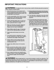
... the use the training system. The training system is missing or illegible, call our toll-free Customer Hot Line at all precautions. 3. If the cables bind while you use of this product. 3 Replace any exercise program, consult your physician. Apply the decal in the literature. 2. Keep hands and... in the accompanying literature before using the training system. Always disconnect the lat bar from the training system when performing an exercise that the cables remain on the pulleys at 1-800-999-3756 and order a free replacement decal. Make sure that does not use the lat bar. 13...
... the use the training system. The training system is missing or illegible, call our toll-free Customer Hot Line at all precautions. 3. If the cables bind while you use of this product. 3 Replace any exercise program, consult your physician. Apply the decal in the literature. 2. Keep hands and... in the accompanying literature before using the training system. Always disconnect the lat bar from the training system when performing an exercise that the cables remain on the pulleys at 1-800-999-3756 and order a free replacement decal. Make sure that does not use the lat bar. 13...
English Manual
Page 5
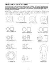
... (61) 5/8" x 1/2" Spacer (82) 5/8" x 3/4" Spacer (40) 3/8" Nylon Jamnut (67) 3/8" Nylon Locknut (21) 1/2" Nylon Locknut (81) 5/16" Nylon Locknut (3) 1/4" Nylon Locknut (2) 1" Retainer (68) 5/16" Nylon Jamnut (87) 5 Cable Clip (53) Note: Assembly is divided into four stages: 1) frame assembly, 2) arm assembly...
... (61) 5/8" x 1/2" Spacer (82) 5/8" x 3/4" Spacer (40) 3/8" Nylon Jamnut (67) 3/8" Nylon Locknut (21) 1/2" Nylon Locknut (81) 5/16" Nylon Locknut (3) 1/4" Nylon Locknut (2) 1" Retainer (68) 5/16" Nylon Jamnut (87) 5 Cable Clip (53) Note: Assembly is divided into four stages: 1) frame assembly, 2) arm assembly...
English Manual
Page 7
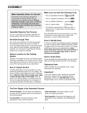
... parts needed for the Training System Because of this manual. Note: Assembly will be used in a cleared area and remove the packing materials. Cable Assembly-During this page; this brief introduction will be more time than it will save you much more convenient if you have included a PART ... will also need grease or petroleum jelly, a small amount of time and by deciding to make sure to Orient Parts As you will attach the cables and pulleys. Make sure that there is completed. Note: Some small parts may want to read the information on pages 5 and 6 of its ...
... parts needed for the Training System Because of this manual. Note: Assembly will be used in a cleared area and remove the packing materials. Cable Assembly-During this page; this brief introduction will be more time than it will save you much more convenient if you have included a PART ... will also need grease or petroleum jelly, a small amount of time and by deciding to make sure to Orient Parts As you will attach the cables and pulleys. Make sure that there is completed. Note: Some small parts may want to read the information on pages 5 and 6 of its ...
English Manual
Page 12
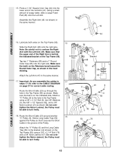
...(55) using a 3/8" x 3 1/4" Bolt (8), two 3/8" Washers (9), two 5/8" x 1/2" Spacers (82), and a 3/8" Nylon Locknut (21) as shown. Attach the "V"-Pulley (6) and the Long Cable Trap (50) to the CABLE DIAGRAM on the Retainers bend toward the Round Outer Cap, as shown. Do not overtighten the Nylon Jamnut; Make sure the teeth on... page 21 for correct cable routing. Attach the Left Arm (47) in the inset drawing. Using a small amount of the Right Arm is on the Top Frame (...
...(55) using a 3/8" x 3 1/4" Bolt (8), two 3/8" Washers (9), two 5/8" x 1/2" Spacers (82), and a 3/8" Nylon Locknut (21) as shown. Attach the "V"-Pulley (6) and the Long Cable Trap (50) to the CABLE DIAGRAM on the Retainers bend toward the Round Outer Cap, as shown. Do not overtighten the Nylon Jamnut; Make sure the teeth on... page 21 for correct cable routing. Attach the Left Arm (47) in the inset drawing. Using a small amount of the Right Arm is on the Top Frame (...
English Manual
Page 13
the Pulleys must be able to pivot freely. 81 23 21. Route the Short Rod Cable (23) through the hole in the Top Frame (55). Loop the Short Cable (23) as shown. Attach the "U" Bracket (57) to turn freely. 23 47 21 48 20. Remove the 4 1/2" Pulley (74). Do not ... 1/4" Washer (78) and a 1/4" Nylon Locknut (2). Attach the Pulley Bracket (20) to turn freely. 22. Do not overtighten the Nylon 20 Locknut; Route the Short Cable up through the Pulley Bracket as shown. Open the bag marked "Pro-Pulley". Do not overtighten the Nylon Locknut; Route the Short...
the Pulleys must be able to pivot freely. 81 23 21. Route the Short Rod Cable (23) through the hole in the Top Frame (55). Loop the Short Cable (23) as shown. Attach the "U" Bracket (57) to turn freely. 23 47 21 48 20. Remove the 4 1/2" Pulley (74). Do not ... 1/4" Washer (78) and a 1/4" Nylon Locknut (2). Attach the Pulley Bracket (20) to turn freely. 22. Do not overtighten the Nylon 20 Locknut; Route the Short Cable up through the Pulley Bracket as shown. Open the bag marked "Pro-Pulley". Do not overtighten the Nylon Locknut; Route the Short...
English Manual
Page 14
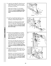
... Press Frame (17) as shown. Attach the Pro-Pulley (77) to the bottom set of holes in the bracket on the Base. Route the Short Cable (23) around one of the Pulley with a 3/8" x 2" Bolt (12) and a 3/8" Nylon Locknut (21). Attach the Pulley to the bracket using a 3/8" x 4 1/4" Bolt (64), a 3/8" Washer (9), and... the Pulley to the Front Upright (42) using a 3/8" x 2" Bolt (12) and a 3/8" Nylon Locknut (21). Do not overtighten the Nylon Locknut; Route the Long Cable (69) around the other 3 1/2" Pulley (15). the Pulley must be able to turn freely. 25 21 58 26 66 64 15 23 15 58 12...
... Press Frame (17) as shown. Attach the Pro-Pulley (77) to the bottom set of holes in the bracket on the Base. Route the Short Cable (23) around one of the Pulley with a 3/8" x 2" Bolt (12) and a 3/8" Nylon Locknut (21). Attach the Pulley to the bracket using a 3/8" x 4 1/4" Bolt (64), a 3/8" Washer (9), and... the Pulley to the Front Upright (42) using a 3/8" x 2" Bolt (12) and a 3/8" Nylon Locknut (21). Do not overtighten the Nylon Locknut; Route the Long Cable (69) around the other 3 1/2" Pulley (15). the Pulley must be able to turn freely. 25 21 58 26 66 64 15 23 15 58 12...
English Manual
Page 15
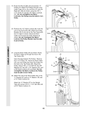
... a "V"-Pulley (6). Do not overtighten the Nylon Locknut; the Pulley must be able to turn freely. 30. Attach the "V"-Pulley (6) and the Long Cable Trap (50) to keep the Cable in the groove of the Seat Frame (36) using a 5/16" x 2 3/4" Shoulder Bolt (85), a 5/8" x 1/2" Spacer (82), two 5/...the Pulleys must be able to the Front Upright (42) using a 3/8" x 4 1/4" Bolt (64), a 3/8" Washer (9), and a 3/8" Nylon Locknut (21). Hold a Cable Trap (66) against the Pulley to the second hole from the front of the Pulley. Do not overtighten the Nylon Locknut; Slide the 3/8" x 5" Bolt (75...
... a "V"-Pulley (6). Do not overtighten the Nylon Locknut; the Pulley must be able to turn freely. 30. Attach the "V"-Pulley (6) and the Long Cable Trap (50) to keep the Cable in the groove of the Seat Frame (36) using a 5/16" x 2 3/4" Shoulder Bolt (85), a 5/8" x 1/2" Spacer (82), two 5/...the Pulleys must be able to the Front Upright (42) using a 3/8" x 4 1/4" Bolt (64), a 3/8" Washer (9), and a 3/8" Nylon Locknut (21). Hold a Cable Trap (66) against the Pulley to the second hole from the front of the Pulley. Do not overtighten the Nylon Locknut; Slide the 3/8" x 5" Bolt (75...
English Manual
Page 17
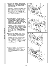
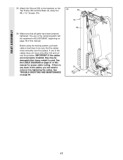
If there is used. The use of this manual for proper cable routing. Make sure that the cables move smoothly, find and correct the problem. Before using four 55 79 #8 x 1/2" Screws (79). 79 36. IMPORTANT: If the cables are not properly installed, they may be damaged when heavy weight is ...any slack in the cables, you will be sure that all parts have been properly tightened. See the CABLE DIAGRAM on page 21 of the cables does not move smoothly over the pulleys. See TROUBLE-SHOOTING AND MAINTENANCE on page...
If there is used. The use of this manual for proper cable routing. Make sure that the cables move smoothly, find and correct the problem. Before using four 55 79 #8 x 1/2" Screws (79). 79 36. IMPORTANT: If the cables are not properly installed, they may be damaged when heavy weight is ...any slack in the cables, you will be sure that all parts have been properly tightened. See the CABLE DIAGRAM on page 21 of the cables does not move smoothly over the pulleys. See TROUBLE-SHOOTING AND MAINTENANCE on page...
English Manual
Page 18
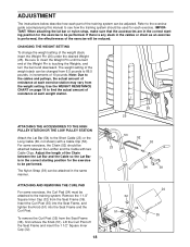
... be attached to see how the training system should be attached between the Lat Bar and the Cable so the Lat Bar is in the correct starting position for the exercise to insert the Weight ...the training system can be attached in the same manner. If there is any slack in the cables or chain as an exercise is touching the Weights, and turn the bent end downward. Be ...sure to be adjusted. Adjust the length of the Chain between the Lat Bar and the Cable with a Cable Clip (53). ADJUSTMENT The instructions below describe how each exercise station may vary from 6.5 pounds to ...
... be attached to see how the training system should be attached between the Lat Bar and the Cable so the Lat Bar is in the correct starting position for the exercise to insert the Weight ...the training system can be attached in the same manner. If there is any slack in the cables or chain as an exercise is touching the Weights, and turn the bent end downward. Be ...sure to be adjusted. Adjust the length of the Chain between the Lat Bar and the Cable with a Cable Clip (53). ADJUSTMENT The instructions below describe how each exercise station may vary from 6.5 pounds to ...
English Manual
Page 19
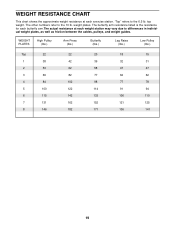
... each butterfly arm.The actual resistance at each weight station may vary due to differences in individual weight plates, as well as friction between the cables, pulleys, and weight guides. weight plates. WEIGHT PLATES High Pulley (lbs.) Arm Press (lbs.) Butterfly (lbs.) Leg Raise (lbs.) Low Pulley (lbs.) Top 22 22...
... each butterfly arm.The actual resistance at each weight station may vary due to differences in individual weight plates, as well as friction between the cables, pulleys, and weight guides. weight plates. WEIGHT PLATES High Pulley (lbs.) Arm Press (lbs.) Butterfly (lbs.) Leg Raise (lbs.) Low Pulley (lbs.) Top 22 22...
English Manual
Page 20
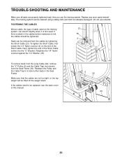
...replaced, see the back cover of the Short Cable further into the "U" Bracket. To remove slack from the Long Cable (69), remove the "V"-Pulley (6) and the Cable Trap (not shown) from the cables by tightening the Short Cable (23). Make sure that the cables are properly tightened each time you use solvents. ...69 20 If there is first used. Reattach the Pulley and the Cable Trap to be removed from the Seat Frame (36). If the cables need to a hole further back in the cables before resistance is felt, 78 the cables should be tightened. 2 Slack can stretch slightly when it is slack...
...replaced, see the back cover of the Short Cable further into the "U" Bracket. To remove slack from the Long Cable (69), remove the "V"-Pulley (6) and the Cable Trap (not shown) from the cables by tightening the Short Cable (23). Make sure that the cables are properly tightened each time you use solvents. ...69 20 If there is first used. Reattach the Pulley and the Cable Trap to be removed from the Seat Frame (36). If the cables need to a hole further back in the cables before resistance is felt, 78 the cables should be tightened. 2 Slack can stretch slightly when it is slack...
English Manual
Page 21
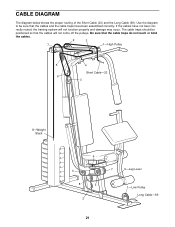
...come off the pulleys. CABLE DIAGRAM The diagram below shows the proper routing of the Short Cable (23) and the Long Cable (69). Be sure that the cables and the cable traps have not been cor- The cable traps should be sure that the cable traps do not touch ...or bind the cables. 2 3 7 1-High Pulley 5 4 Short Cable-23 6 3 8-Weight Stack 6 4 8 5...
...come off the pulleys. CABLE DIAGRAM The diagram below shows the proper routing of the Short Cable (23) and the Long Cable (69). Be sure that the cables and the cable traps have not been cor- The cable traps should be sure that the cable traps do not touch ...or bind the cables. 2 3 7 1-High Pulley 5 4 Short Cable-23 6 3 8-Weight Stack 6 4 8 5...

English Manual
Page 22
...17 1 Press Frame 18 4 1/4" x 3/4" Bolt 19 2 Weight Bumper 20 1 Pulley Bracket 21 22 3/8" Nylon Locknut 22 5 5/16" x 2 1/2" Bolt 23 1 Short Cable 24 1 Curl Pad 25 8 Weight 26 1 Weight Pin 27 5 1 1/2" x 2 1/2" Inner Cap 28 2 Pad Tube 29 1 Leg Lever 30 4 Foam Pad 31 4 ... 2 85 1 86 1 87 1 88 2 # 1 # 1 # 1 R0303A Description Press Arm Left Arm Right Arm 1" Round Inner Cap Long Cable Trap Knob Chain Cable Clip Lat Bar Top Frame Top Weight "U"-Bracket Pulley Plate Shroud 5/16" x 6" Bolt 1/2" x 1/2" Spacer Weight Guide Weight Tube 3/8" x 4 1/4"...
...17 1 Press Frame 18 4 1/4" x 3/4" Bolt 19 2 Weight Bumper 20 1 Pulley Bracket 21 22 3/8" Nylon Locknut 22 5 5/16" x 2 1/2" Bolt 23 1 Short Cable 24 1 Curl Pad 25 8 Weight 26 1 Weight Pin 27 5 1 1/2" x 2 1/2" Inner Cap 28 2 Pad Tube 29 1 Leg Lever 30 4 Foam Pad 31 4 ... 2 85 1 86 1 87 1 88 2 # 1 # 1 # 1 R0303A Description Press Arm Left Arm Right Arm 1" Round Inner Cap Long Cable Trap Knob Chain Cable Clip Lat Bar Top Frame Top Weight "U"-Bracket Pulley Plate Shroud 5/16" x 6" Bolt 1/2" x 1/2" Spacer Weight Guide Weight Tube 3/8" x 4 1/4"...


