User Manual
Page 3
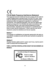
... is operated in which case the user will be used in order to comply with the instruction manual, may cause harmful interference to radio communications. VIA EPIA-M Mini-ITX Mainboard Tested to comply with the limits for compliance could void the user's authority to operate the equipment. VOIR LA NOTICE D'INSTALLATION AVANT DE RACCORDER...
... is operated in which case the user will be used in order to comply with the instruction manual, may cause harmful interference to radio communications. VIA EPIA-M Mini-ITX Mainboard Tested to comply with the limits for compliance could void the user's authority to operate the equipment. VOIR LA NOTICE D'INSTALLATION AVANT DE RACCORDER...
User Manual
Page 6
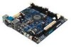
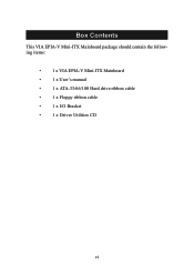
Box Contents This VIA EPIA-V Mini-ITX Mainboard package should contain the following items: • 1 x VIA EPIA-V Mini-ITX Mainboard • 1 x User's manual • 1 x ATA-33/66/100 Hard drive ribbon cable • 1 x Floppy ribbon cable • 1 x I/O Bracket • 1 x Driver Utilities CD vi
Box Contents This VIA EPIA-V Mini-ITX Mainboard package should contain the following items: • 1 x VIA EPIA-V Mini-ITX Mainboard • 1 x User's manual • 1 x ATA-33/66/100 Hard drive ribbon cable • 1 x Floppy ribbon cable • 1 x I/O Bracket • 1 x Driver Utilities CD vi

User Manual
Page 7
Contents Specifications 1-1 Mainboard Specifications 1-2 Mainboard Layout 1-4 Connectors Guide 1-5 Installation 2-1 CPU 2-2 The VIA C3™ E-Series Processor 2-2 The VIA Eden Processor 2-3 Memory Installation 2-4 SDRAM Module Installation Procedures 2-4 Available SDRAM Configurations 2-5 Power Supply 2-6 ATX 20-Pin Power Connector: ATXPWR 2-6 Back Panel 2-7 Mouse Connector: JMS1 2-7 Keyboard ...
Contents Specifications 1-1 Mainboard Specifications 1-2 Mainboard Layout 1-4 Connectors Guide 1-5 Installation 2-1 CPU 2-2 The VIA C3™ E-Series Processor 2-2 The VIA Eden Processor 2-3 Memory Installation 2-4 SDRAM Module Installation Procedures 2-4 Available SDRAM Configurations 2-5 Power Supply 2-6 ATX 20-Pin Power Connector: ATXPWR 2-6 Back Panel 2-7 Mouse Connector: JMS1 2-7 Keyboard ...
User Manual
Page 10
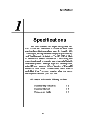
.... Through high level of integration, mini-ITX only occupy 66% of the size of the company's open industrywide Total Connectivity initiative. 1 Specifications Specifications The ultra-compact and highly intergrated VIA EPIA-V Mini-ITX Mainboard is the smallest form factor mainboard specification available today, developed by VIA Technologies, Inc as part of FlexATX mainboard form factor. This chapter includes the...
.... Through high level of integration, mini-ITX only occupy 66% of the size of the company's open industrywide Total Connectivity initiative. 1 Specifications Specifications The ultra-compact and highly intergrated VIA EPIA-V Mini-ITX Mainboard is the smallest form factor mainboard specification available today, developed by VIA Technologies, Inc as part of FlexATX mainboard form factor. This chapter includes the...
User Manual
Page 13
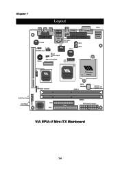
... VT8231 J5 FIR Module Connector North Bridge VT8601A Processor EBGA Clock Generator DIMM 1 J13 Host Frequency Select BIOS ROM FDD IDE 1 DIMM 2 ATX Power Connector VIA EPIA-V Mini-ITX Mainboard 1-4
... VT8231 J5 FIR Module Connector North Bridge VT8601A Processor EBGA Clock Generator DIMM 1 J13 Host Frequency Select BIOS ROM FDD IDE 1 DIMM 2 ATX Power Connector VIA EPIA-V Mini-ITX Mainboard 1-4
User Manual
Page 16
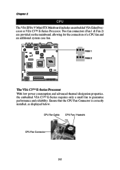
...™ E-Series requires only a small fan to guarantee performance and reliability. Chapter 2 CPU The VIA EPIA-V Mini-ITX Mainboard includes an embedded VIA Eden Processor or VIA C3™ E-Series Processor. Two fan connectors (Fan 1 & Fan 2) are provided on the mainboard, allowing for the connection of a CPU fan and an additional system case fan. Ensure that the...
...™ E-Series requires only a small fan to guarantee performance and reliability. Chapter 2 CPU The VIA EPIA-V Mini-ITX Mainboard includes an embedded VIA Eden Processor or VIA C3™ E-Series Processor. Two fan connectors (Fan 1 & Fan 2) are provided on the mainboard, allowing for the connection of a CPU fan and an additional system case fan. Ensure that the...

User Manual
Page 18
Chapter 2 Memory Installation The VIA EPIA-V Mini-ITX Mainboard provides two 168-pin DIMM slots for PC 100/133 SDRAM memory modules. To operate properly, at either end of the DIMM slot outwards. 2.) Align ...
Chapter 2 Memory Installation The VIA EPIA-V Mini-ITX Mainboard provides two 168-pin DIMM slots for PC 100/133 SDRAM memory modules. To operate properly, at either end of the DIMM slot outwards. 2.) Align ...
User Manual
Page 19
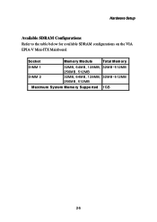
Socket Memory Module Total M emory DIMM 1 DIMM 2 32MB, 64MB, 128MB, 32MB~512MB 256MB, 512MB 32MB, 64MB, 128MB, 32MB~512MB 256MB, 512MB Maximum System Memory Supported 1GB 2-5 Hardware Setup Available SDRAM Configurations Refer to the table below for available SDRAM configurations on the VIA EPIA-V Mini-ITX Mainboard.
Socket Memory Module Total M emory DIMM 1 DIMM 2 32MB, 64MB, 128MB, 32MB~512MB 256MB, 512MB 32MB, 64MB, 128MB, 32MB~512MB 256MB, 512MB Maximum System Memory Supported 1GB 2-5 Hardware Setup Available SDRAM Configurations Refer to the table below for available SDRAM configurations on the VIA EPIA-V Mini-ITX Mainboard.

User Manual
Page 20
... 6 5V 7 GND 8 PW_OK 9 5V_SB 10 12V PIN SIGNAL 11 3.3V 12 -12V 13 GND 14 PS_ON 15 GND 16 GND 17 GND 18 NC 19 5V 20 5V 2-6 Chapter 2 Power Supply The VIA EPIA-V Mini-ITX Mainboard requires an ATX power supply to ensure that all components are correctly aligned. Before inserting the power supply...
... 6 5V 7 GND 8 PW_OK 9 5V_SB 10 12V PIN SIGNAL 11 3.3V 12 -12V 13 GND 14 PS_ON 15 GND 16 GND 17 GND 18 NC 19 5V 20 5V 2-6 Chapter 2 Power Supply The VIA EPIA-V Mini-ITX Mainboard requires an ATX power supply to ensure that all components are correctly aligned. Before inserting the power supply...

User Manual
Page 21
... Definition PIN SIGNAL DESCRIPTION 1 Keyboard DATA Keyboard DATA 2 NC No connection 3 GND Ground 4 VCC +5V 5. Hardware Setup Back Panel The back panel of the VIA EPIA-V Mini-ITX Mainboard contains the following connectors: PS/2 Mouse LPT Connector RJ-45 Port COM Port PS/2 Keyboard S-Video Port USB Ports CRT Connector RCA Video or S / P DIF...
... Definition PIN SIGNAL DESCRIPTION 1 Keyboard DATA Keyboard DATA 2 NC No connection 3 GND Ground 4 VCC +5V 5. Hardware Setup Back Panel The back panel of the VIA EPIA-V Mini-ITX Mainboard contains the following connectors: PS/2 Mouse LPT Connector RJ-45 Port COM Port PS/2 Keyboard S-Video Port USB Ports CRT Connector RCA Video or S / P DIF...

User Manual
Page 22
... DATA7 Data7 10 ACK# Acknowledge 11 BUSY Busy 12 PE Paper End 13 SELECT Select 14 AUTO FEED# Automatic Feed 15 ERR# Error 16 INIT# Initialize Printer 17 SLIN# Select In 18 GND Ground 19 GND Ground 20 GND Ground 21 GND Ground 22 GND Ground 23 GND ...Ground 24 GND Ground 25 GND Ground 2-8 Parallel Port Connector: LPT1 The mainboard provides a 25-pin female connector for connection to the Local Area Network (LAN). A parallel port is a standard printer port that supports Enhanced ...
... DATA7 Data7 10 ACK# Acknowledge 11 BUSY Busy 12 PE Paper End 13 SELECT Select 14 AUTO FEED# Automatic Feed 15 ERR# Error 16 INIT# Initialize Printer 17 SLIN# Select In 18 GND Ground 19 GND Ground 20 GND Ground 21 GND Ground 22 GND Ground 23 GND ...Ground 24 GND Ground 25 GND Ground 2-8 Parallel Port Connector: LPT1 The mainboard provides a 25-pin female connector for connection to the Local Area Network (LAN). A parallel port is a standard printer port that supports Enhanced ...

User Manual
Page 23
... SIGNAL DESCRIPTION 1 DCD 2 SIN 3 SOUT 4 DTR 5. The Line-In connector can attach a serial mouse or other audio devices. Hardware Setup Serial Port Connectors: COM 1 The mainboard offers one 9-pin male Serial Port connector (COM 1) . You can be used for speakers or headphones. The Mic-In connector is a connector for an external...
... SIGNAL DESCRIPTION 1 DCD 2 SIN 3 SOUT 4 DTR 5. The Line-In connector can attach a serial mouse or other audio devices. Hardware Setup Serial Port Connectors: COM 1 The mainboard offers one 9-pin male Serial Port connector (COM 1) . You can be used for speakers or headphones. The Mic-In connector is a connector for an external...

User Manual
Page 24
... instructions. 2-10 These connectors utilize the provided IDE hard disk cable. IDE1 can connect up to IDE1. Chapter 2 Connectors The VIA EPIA-V Mini-ITX Mainboard provides the following connectors: Hard Disk Connectors: IDE1 The mainboard has a 32-bit Enhanced PCI IDE and Ultra DMA 33/66/100 controller that provides PIO mode 0~4, Bus Master, and...
... instructions. 2-10 These connectors utilize the provided IDE hard disk cable. IDE1 can connect up to IDE1. Chapter 2 Connectors The VIA EPIA-V Mini-ITX Mainboard provides the following connectors: Hard Disk Connectors: IDE1 The mainboard has a 32-bit Enhanced PCI IDE and Ultra DMA 33/66/100 controller that provides PIO mode 0~4, Bus Master, and...
User Manual
Page 29
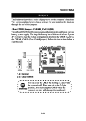
This section explains how to change settings for your mainboard's functions through the use the CLEAR_CMOS (Clear CMOS jumper). Then return it to set the computer's functions. If you want to clear the data: 1 3 1 1 3 3 Normal ...-life battery has a lifetime of the jumpers. Avoid clearing the CMOS while the WARNING! Hardware Setup Jumpers The Mainboard provides a series of jumpers to the 2-3 pin position. system is off. this will damage the mainboard. 2-15 Clear CMOS Jumper: CLEAR_CMOS (J10) The onboard CMOS RAM stores system configuration data and has an...
This section explains how to change settings for your mainboard's functions through the use the CLEAR_CMOS (Clear CMOS jumper). Then return it to set the computer's functions. If you want to clear the data: 1 3 1 1 3 3 Normal ...-life battery has a lifetime of the jumpers. Avoid clearing the CMOS while the WARNING! Hardware Setup Jumpers The Mainboard provides a series of jumpers to the 2-3 pin position. system is off. this will damage the mainboard. 2-15 Clear CMOS Jumper: CLEAR_CMOS (J10) The onboard CMOS RAM stores system configuration data and has an...

User Manual
Page 30
J13 Host Frequency Select Overclocking WARNING! We do not guarantee the damages or risks caused by operation beyond product specifications is not designed to support overclocking. The three available options are 66MHz, 100MHz and 133MHz. Any attempt to select the host frequency bus speed of the mainboard. Chapter 2 Host Frequency Select (J13) This jumper can be used to operate beyond product specifications. 2-16 This motherboard is not recommended.
J13 Host Frequency Select Overclocking WARNING! We do not guarantee the damages or risks caused by operation beyond product specifications is not designed to support overclocking. The three available options are 66MHz, 100MHz and 133MHz. Any attempt to select the host frequency bus speed of the mainboard. Chapter 2 Host Frequency Select (J13) This jumper can be used to operate beyond product specifications. 2-16 This motherboard is not recommended.

User Manual
Page 47
...Parallel Port ECP Mode Use DMA ECP utilises a DMA channel. Disable the controller if you want to use . 3-14 VIA-3043 OnChip LAN Decide whether to invoke the boot ROM of VIA-3043 onchip LAN. Onboard Parallel Mode Set the parallel port mode. Choosing "ECP + EPP" will be enabled; Setting ...Keyboard Support for ECP use other controller cards to connect an audio device. Chapter 3 AC97 Audio Auto allows the mainboard to detect whether an audio device is detected, the onboard VIA AC'97 (Audio Codec'97) controller will allow the onboard parallel port to support both the ECP and EPP...
...Parallel Port ECP Mode Use DMA ECP utilises a DMA channel. Disable the controller if you want to use . 3-14 VIA-3043 OnChip LAN Decide whether to invoke the boot ROM of VIA-3043 onchip LAN. Onboard Parallel Mode Set the parallel port mode. Choosing "ECP + EPP" will be enabled; Setting ...Keyboard Support for ECP use other controller cards to connect an audio device. Chapter 3 AC97 Audio Auto allows the mainboard to detect whether an audio device is detected, the onboard VIA AC'97 (Audio Codec'97) controller will allow the onboard parallel port to support both the ECP and EPP...

User Manual
Page 58
These values are set by the mainboard manufacturer to the default Fail Safe values. BIOS Setup Load Fail-Safe Defaults This option on the main menu allows users to restore all the BIOS settings to provide the most stable system. When you select Load-Fail Safe Defaults, a message as below appears: Pressing 'Y' loads the default BIOS values that provide a minimal and stable system configuration. 3-25
These values are set by the mainboard manufacturer to the default Fail Safe values. BIOS Setup Load Fail-Safe Defaults This option on the main menu allows users to restore all the BIOS settings to provide the most stable system. When you select Load-Fail Safe Defaults, a message as below appears: Pressing 'Y' loads the default BIOS values that provide a minimal and stable system configuration. 3-25

User Manual
Page 59
Chapter 3 Load Optimized Defaults This option on the main menu allows users to restore all the BIOS settings to the default Optimized values. When you select Load Optimized Defaults, a message as below appears: Pressing 'Y' loads the default values that are the default values also set by the mainboard manufacturer for optimal and stable system performance. 3-26 The Optimized Defaults are factory settings for both optimized and stable performance of the mainboard.
Chapter 3 Load Optimized Defaults This option on the main menu allows users to restore all the BIOS settings to the default Optimized values. When you select Load Optimized Defaults, a message as below appears: Pressing 'Y' loads the default values that are the default values also set by the mainboard manufacturer for optimal and stable system performance. 3-26 The Optimized Defaults are factory settings for both optimized and stable performance of the mainboard.
User Manual
Page 64
It consists of each mainboard drivers and applications. The applications will only function correctly if the necessary drivers are already installed. 4-1 4 Driver Setup Software Setup This chapter gives you brief descriptions of the following topic: Driver Utilities CD Content 4-2 Note: You must install VIA chipset drivers first before installing other drivers such as audio or VGA drivers.
It consists of each mainboard drivers and applications. The applications will only function correctly if the necessary drivers are already installed. 4-1 4 Driver Setup Software Setup This chapter gives you brief descriptions of the following topic: Driver Utilities CD Content 4-2 Note: You must install VIA chipset drivers first before installing other drivers such as audio or VGA drivers.
User Manual
Page 65
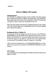
...Start\Run. (Please note that you type the correct letter of the mainboard. CD Content Upon running the CD, the following driver utilities and software menu screen appears as follow: 4-2 Please visit VIA's website (http://www.viamainboard.com/) for the CD. Chapter 4 ...Driver Utilities CD Content Getting Started The VIA EPIA-V mainboard includes a Driver Utilities CD which contains driver utilities and software to time....
...Start\Run. (Please note that you type the correct letter of the mainboard. CD Content Upon running the CD, the following driver utilities and software menu screen appears as follow: 4-2 Please visit VIA's website (http://www.viamainboard.com/) for the CD. Chapter 4 ...Driver Utilities CD Content Getting Started The VIA EPIA-V mainboard includes a Driver Utilities CD which contains driver utilities and software to time....
