User Manual
Page 2
... alter product designs, layouts or drivers without express written authorization from the use, disuse or misuse of this or any loss of data or profits. The information provided in this manual "as is possible that may contain technical inaccuracies or typographical or other VIA product. No Warranty VIA has made every effort to the installation of any kind...
... alter product designs, layouts or drivers without express written authorization from the use, disuse or misuse of this or any loss of data or profits. The information provided in this manual "as is possible that may contain technical inaccuracies or typographical or other VIA product. No Warranty VIA has made every effort to the installation of any kind...

User Manual
Page 7
... Mainboard Specifications 1-2 Mainboard Layout 1-4 Connectors Guide 1-5 Installation 2-1 CPU 2-2 The VIA C3™ E-Series Processor 2-2 The VIA Eden Processor 2-3 Memory Installation 2-4 SDRAM Module Installation Procedures 2-4 Available SDRAM Configurations 2-5 Power Supply 2-6 ATX 20-Pin Power Connector: ATXPWR 2-6 Back Panel 2-7 Mouse Connector: JMS1 2-7 Keyboard Connector: JKB1 2-7 USB Port Connectors 2-8 RJ-45 NIC Port 2-8 Parallel Port Connector: LPT1 2-8 Serial Port Connector: COM 1 2-9 S-Video Port 2-9 Audio Port Connectors 2-9 RCA Video or S/PDIF Port 2-9 VGA...
... Mainboard Specifications 1-2 Mainboard Layout 1-4 Connectors Guide 1-5 Installation 2-1 CPU 2-2 The VIA C3™ E-Series Processor 2-2 The VIA Eden Processor 2-3 Memory Installation 2-4 SDRAM Module Installation Procedures 2-4 Available SDRAM Configurations 2-5 Power Supply 2-6 ATX 20-Pin Power Connector: ATXPWR 2-6 Back Panel 2-7 Mouse Connector: JMS1 2-7 Keyboard Connector: JKB1 2-7 USB Port Connectors 2-8 RJ-45 NIC Port 2-8 Parallel Port Connector: LPT1 2-8 Serial Port Connector: COM 1 2-9 S-Video Port 2-9 Audio Port Connectors 2-9 RCA Video or S/PDIF Port 2-9 VGA...

User Manual
Page 8
...Disk Drive Connector: FDD 2-14 Jumpers 2-15 Clear CMOS Jumper: CLEAR_CMOS 2-15 Host Frequency Select (J13 2-16 Auto Reboot Function Setting (J2 2-17 RCA Video or S/PDIF Select (J11 2-17 Slots 2-18 PCI Slots 2-18 PCI Interrupt Request Routing 2-19 BIOS Setup 3-1 Entering Setup 3-2 Control Keys 3-2 Getting Help 3-3 The Main Menu 3-4 Standard CMOS Features 3-6 Advanced BIOS Features 3-8 Advanced Chipset Features 3-11 Integrated Peripherals 3-13 Power Management Setup 3-16 PNP/PCI Configurations 3-21 PC Health Status 3-23 Frequency/Voltage Control 3-24 Load Fail-Safe Defaults...
...Disk Drive Connector: FDD 2-14 Jumpers 2-15 Clear CMOS Jumper: CLEAR_CMOS 2-15 Host Frequency Select (J13 2-16 Auto Reboot Function Setting (J2 2-17 RCA Video or S/PDIF Select (J11 2-17 Slots 2-18 PCI Slots 2-18 PCI Interrupt Request Routing 2-19 BIOS Setup 3-1 Entering Setup 3-2 Control Keys 3-2 Getting Help 3-3 The Main Menu 3-4 Standard CMOS Features 3-6 Advanced BIOS Features 3-8 Advanced Chipset Features 3-11 Integrated Peripherals 3-13 Power Management Setup 3-16 PNP/PCI Configurations 3-21 PC Health Status 3-23 Frequency/Voltage Control 3-24 Load Fail-Safe Defaults...
User Manual
Page 12
... for 2 USB 1.1 ports • CD Audio-in connector • FIR connector • PS2 connector • Wake-on-Modem • CPU/Sys FAN Back Panel I/O • 1 PS2 mouse port • 1 PS2 keyboard port • 1 Parallel • 1 RJ45 LAN port • 1 Serial port • 2 USB 1.1 ports • 1 VGA port • 1 RCA port (S/PDIF or TV out) • 1 S-Video port Power • Supports ATX type power supply Onboard Floppy • 1 FDD connector BIOS • Award BIOS • 2/4Mbit flash memory Form Factor • Mini-ITX (4 layers) • 17 cm x 17 cm 1-3 Specifications
... for 2 USB 1.1 ports • CD Audio-in connector • FIR connector • PS2 connector • Wake-on-Modem • CPU/Sys FAN Back Panel I/O • 1 PS2 mouse port • 1 PS2 keyboard port • 1 Parallel • 1 RJ45 LAN port • 1 Serial port • 2 USB 1.1 ports • 1 VGA port • 1 RCA port (S/PDIF or TV out) • 1 S-Video port Power • Supports ATX type power supply Onboard Floppy • 1 FDD connector BIOS • Award BIOS • 2/4Mbit flash memory Form Factor • Mini-ITX (4 layers) • 17 cm x 17 cm 1-3 Specifications
User Manual
Page 13
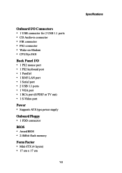
... Port VT1612A F_USB J7 CD-ROM Line-In USB 0 USB 1 LAN RJ45 LAN RCA Video or S/PDIF S-Video CRT Connector LPT Connector J11 RCA Video S/PDIF FAN 1 FAN 2 VT6103 TV Out Buzzer J10 Clear CMOS J8 Wake up On Modem Battery CR2032 VT1621 J12 Video In Connector PS / 2 Keyboard Mouse PS2 Connector J6 South Bridge VT8231 J5 FIR Module Connector North Bridge VT8601A Processor EBGA Clock Generator DIMM 1 J13 Host Frequency Select BIOS ROM FDD IDE 1 DIMM 2 ATX Power Connector VIA EPIA-V Mini-ITX Mainboard...
... Port VT1612A F_USB J7 CD-ROM Line-In USB 0 USB 1 LAN RJ45 LAN RCA Video or S/PDIF S-Video CRT Connector LPT Connector J11 RCA Video S/PDIF FAN 1 FAN 2 VT6103 TV Out Buzzer J10 Clear CMOS J8 Wake up On Modem Battery CR2032 VT1621 J12 Video In Connector PS / 2 Keyboard Mouse PS2 Connector J6 South Bridge VT8231 J5 FIR Module Connector North Bridge VT8601A Processor EBGA Clock Generator DIMM 1 J13 Host Frequency Select BIOS ROM FDD IDE 1 DIMM 2 ATX Power Connector VIA EPIA-V Mini-ITX Mainboard...
User Manual
Page 14
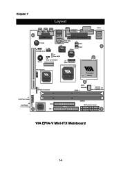
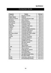
...J11 PCI Slot PCI IRQ Function Fan power connectors DIMM slot Connecting ATX power supply Mouse connector Keyboard connector Parallel port connector Connecting to a LAN Connecting to USB devices COM port connector Connecting Headphones/Speakers Connecting an audio device Connecting a Micorphone Connecting to RCA Video or SPDIF Connecting to S-Video Connect to a VGA monitor Connecting an IDE device Front panel connector CD-ROM Line in connector FIR module connector PS2 connector Wake on Modem USB Port 2 &3 Connector Video in connector Floppy disk drive connector Clear CMOS jumper Host Frequency...
...J11 PCI Slot PCI IRQ Function Fan power connectors DIMM slot Connecting ATX power supply Mouse connector Keyboard connector Parallel port connector Connecting to a LAN Connecting to USB devices COM port connector Connecting Headphones/Speakers Connecting an audio device Connecting a Micorphone Connecting to RCA Video or SPDIF Connecting to S-Video Connect to a VGA monitor Connecting an IDE device Front panel connector CD-ROM Line in connector FIR module connector PS2 connector Wake on Modem USB Port 2 &3 Connector Video in connector Floppy disk drive connector Clear CMOS jumper Host Frequency...

User Manual
Page 21
... +5V Mouse clock No connection Pin Definition PIN SIGNAL DESCRIPTION 1 Keyboard DATA Keyboard DATA 2 NC No connection 3 GND Ground 4 VCC +5V 5. Hardware Setup Back Panel The back panel of the VIA EPIA-V Mini-ITX Mainboard contains the following connectors: PS/2 Mouse LPT Connector RJ-45 Port COM Port PS/2 Keyboard S-Video Port USB Ports CRT Connector RCA Video or S / P DIF Port Line Line Mic Out In In (Audio Connectors) Mouse Connector: JMS1 Keyboard Connector: JKB1 The mainboard provides a standard The mainboard provides a standard...
... +5V Mouse clock No connection Pin Definition PIN SIGNAL DESCRIPTION 1 Keyboard DATA Keyboard DATA 2 NC No connection 3 GND Ground 4 VCC +5V 5. Hardware Setup Back Panel The back panel of the VIA EPIA-V Mini-ITX Mainboard contains the following connectors: PS/2 Mouse LPT Connector RJ-45 Port COM Port PS/2 Keyboard S-Video Port USB Ports CRT Connector RCA Video or S / P DIF Port Line Line Mic Out In In (Audio Connectors) Mouse Connector: JMS1 Keyboard Connector: JKB1 The mainboard provides a standard The mainboard provides a standard...

User Manual
Page 24
... install two hard disks on cable, you must configure the second drive to two hard disk drives, CD-ROM, LS120 and other devices. IDE 1 IDE1 (Primary IDE Connector) The first hard drive should always be connected to the hard disk documentation supplied by setting its jumper. Refer to IDE1. These connectors utilize the provided IDE hard disk cable. Chapter 2 Connectors The VIA EPIA-V Mini-ITX Mainboard provides the following connectors: Hard Disk Connectors: IDE1 The mainboard has a 32-bit Enhanced PCI IDE and Ultra DMA 33/66/100 controller that provides PIO mode 0~4, Bus...
... install two hard disks on cable, you must configure the second drive to two hard disk drives, CD-ROM, LS120 and other devices. IDE 1 IDE1 (Primary IDE Connector) The first hard drive should always be connected to the hard disk documentation supplied by setting its jumper. Refer to IDE1. These connectors utilize the provided IDE hard disk cable. Chapter 2 Connectors The VIA EPIA-V Mini-ITX Mainboard provides the following connectors: Hard Disk Connectors: IDE1 The mainboard has a 32-bit Enhanced PCI IDE and Ultra DMA 33/66/100 controller that provides PIO mode 0~4, Bus...

User Manual
Page 31
Hardware Setup Auto Reboot Function Setting (J2) This jumper enables or disables the Auto Reboot Function Setting. For S/ PDIF out, short 3-4. 31 42 1-2: RCA Video 3-4: S/PDIF 2-17 For TV-out composite function, please short 1-2. When enabled, the system will automatically reboot in the event it of sudden power outage. 1 1-2: Disable 2-3: Enable RCA Video or S/PDIF Select (J11) Users can select either RCA Video or S/PDIF as the enabled function on the dual-purpose port.
Hardware Setup Auto Reboot Function Setting (J2) This jumper enables or disables the Auto Reboot Function Setting. For S/ PDIF out, short 3-4. 31 42 1-2: RCA Video 3-4: S/PDIF 2-17 For TV-out composite function, please short 1-2. When enabled, the system will automatically reboot in the event it of sudden power outage. 1 1-2: Disable 2-3: Enable RCA Video or S/PDIF Select (J11) Users can select either RCA Video or S/PDIF as the enabled function on the dual-purpose port.

User Manual
Page 40
... size of cylinders. Number of the storage device. Cylinder location of the landing zone. If you enter improper information for this category. The settings are Mode 0/1/2/3/4, Auto. BIOS Setup IDE Primary Master/Slave Press to enter the sub-menu and the following screen appears: The specifications of your hard disk vendor or system manufacturer. Select Auto whenever possible. The settings are Disabled and Auto. 3-7 The hard disk will not work properly if you select Manual...
... size of cylinders. Number of the storage device. Cylinder location of the landing zone. If you enter improper information for this category. The settings are Mode 0/1/2/3/4, Auto. BIOS Setup IDE Primary Master/Slave Press to enter the sub-menu and the following screen appears: The specifications of your hard disk vendor or system manufacturer. Select Auto whenever possible. The settings are Disabled and Auto. 3-7 The hard disk will not work properly if you select Manual...

User Manual
Page 41
... time. The settings are: 3-8 CPU L2 Cache ECC Checking Set the ECC (Error-Correcting Code) feature for IDE Hard Disk boot sector protection. Allow BIOS to load the disk operating system. First/Second/Third Boot Device Set the boot device sequence as BIOS attempts to skip some check items during POST. Facilitates error detection/correction when data passes through Level 2 cache. Settings: Disabled and Enabled. Settings: Enabled and Disabled. Settings: Enabled and Disabled. Settings: Enabled and Disabled. Processor Number Feature Set the CPU internal serial number. If...
... time. The settings are: 3-8 CPU L2 Cache ECC Checking Set the ECC (Error-Correcting Code) feature for IDE Hard Disk boot sector protection. Allow BIOS to load the disk operating system. First/Second/Third Boot Device Set the boot device sequence as BIOS attempts to skip some check items during POST. Facilitates error detection/correction when data passes through Level 2 cache. Settings: Disabled and Enabled. Settings: Enabled and Disabled. Settings: Enabled and Disabled. Settings: Enabled and Disabled. Processor Number Feature Set the CPU internal serial number. If...

User Manual
Page 42
... option makes a pin in the keyboard controller control Gate A20. Boot Up NumLock Status Set the NumLock status when the system is 40 or 80 tracks. "On" will turn key pad into number keys, and "Off" will boot from third HDD. The system will boot from floppy drive. Settings: Enabled and Disabled. BIOS Setup Floppy LS120 HDD-0 SCSI CD-ROM HDD-1 HDD-2 HDD-3 ZIP100 USB-FDD USB-ZIP USB-CDROM USB-HDD LAN Disabled The system will boot from fourth HDD. The system will boot from USB...
... option makes a pin in the keyboard controller control Gate A20. Boot Up NumLock Status Set the NumLock status when the system is 40 or 80 tracks. "On" will turn key pad into number keys, and "Off" will boot from third HDD. The system will boot from floppy drive. Settings: Enabled and Disabled. BIOS Setup Floppy LS120 HDD-0 SCSI CD-ROM HDD-1 HDD-2 HDD-3 ZIP100 USB-FDD USB-ZIP USB-CDROM USB-HDD LAN Disabled The system will boot from fourth HDD. The system will boot from USB...

User Manual
Page 43
... summary information during BIOS bootup process. Settings: Enabled and Disabled. 3-10 Settings: 6, 8, 10, 12, 15, 20, 24 and 30. Security Option Specifies the type of BIOS password protection that is powered on or when end users try to run Setup. Display Full Screen logo Show full screen logo during BIOS bootup process. This item allows you to select the delay between when the key was first pressed...
... summary information during BIOS bootup process. Settings: Enabled and Disabled. 3-10 Settings: 6, 8, 10, 12, 15, 20, 24 and 30. Security Option Specifies the type of BIOS password protection that is powered on or when end users try to run Setup. Display Full Screen logo Show full screen logo during BIOS bootup process. This item allows you to select the delay between when the key was first pressed...

User Manual
Page 45
.... Settings: Dedot Crawl and Dot Crawl. TV Standard Set the TV standard you would like to finish. Chapter 3 P2C/C2P Concurrency Fast R-W Turn Around PCI Dynamic Bursting PCI#2 Access #1 Retry The settings are Enabled and Disabled. The settings are Enabled and Disabled. The settings are Enabled and Disabled. TV Connector Type Choose TV connect type. Settings: NTSC and PAL. The settings are Enabled and Disabled. If Disabled, CPU must wait for PCI bus cycle to use for displaying. Settings: Enabled and Disabled.
.... Settings: Dedot Crawl and Dot Crawl. TV Standard Set the TV standard you would like to finish. Chapter 3 P2C/C2P Concurrency Fast R-W Turn Around PCI Dynamic Bursting PCI#2 Access #1 Retry The settings are Enabled and Disabled. The settings are Enabled and Disabled. The settings are Enabled and Disabled. TV Connector Type Choose TV connect type. Settings: NTSC and PAL. The settings are Enabled and Disabled. If Disabled, CPU must wait for PCI bus cycle to use for displaying. Settings: Enabled and Disabled.

User Manual
Page 47
...." Onboard Parallel Mode Set the parallel port mode. Settings are: Normal : Standard Parallel Port EPP : Enhanced Parallel Port ECP : Extended Capability Port ECP + EPP: Extended Capability Port + Enhanced Parallel Port ECP Mode Use DMA ECP utilises a DMA channel. USB Keyboard Support Enable USB Keyboard Support for ECP use other controller cards to use . 3-14 neously. Select DMA channel for DOS and Windows 95. Disable the controller if you want to connect an audio device. VIA-3043 OnChip LAN Decide whether to detect whether an audio device...
...." Onboard Parallel Mode Set the parallel port mode. Settings are: Normal : Standard Parallel Port EPP : Enhanced Parallel Port ECP : Extended Capability Port ECP + EPP: Extended Capability Port + Enhanced Parallel Port ECP Mode Use DMA ECP utilises a DMA channel. USB Keyboard Support Enable USB Keyboard Support for ECP use other controller cards to use . 3-14 neously. Select DMA channel for DOS and Windows 95. Disable the controller if you want to connect an audio device. VIA-3043 OnChip LAN Decide whether to detect whether an audio device...

User Manual
Page 48
.... Settings: Enabled and Disabled. Settings: 378/IRQ7, 278/IRQ5, 3BC/IRQ7 and Disabled. Selecting Auto allows BIOS to enter the sub-menu and the following screen appears: Onboard FDD Controller Enable the onboard floppy controller. Onboard FIR Select Enable onboard fast IR functions. Settings: Disabled, 3F8/IRQ4, 2F8/IRQ3, 3E8/ IRQ4, 2E8/IRQ3 and Auto. Settings: IRQ3, IRQ 9, IRQ 10 and Disabled. 3-15 Onboard Serial Port 1 Set the base I/O port address and IRQ for the onboard serial port A/serial port B. Select "Enabled" when you have installed a floppy disk drive. BIOS Setup VIA...
.... Settings: Enabled and Disabled. Settings: 378/IRQ7, 278/IRQ5, 3BC/IRQ7 and Disabled. Selecting Auto allows BIOS to enter the sub-menu and the following screen appears: Onboard FDD Controller Enable the onboard floppy controller. Onboard FIR Select Enable onboard fast IR functions. Settings: Disabled, 3F8/IRQ4, 2F8/IRQ3, 3E8/ IRQ4, 2E8/IRQ3 and Auto. Settings: IRQ3, IRQ 9, IRQ 10 and Disabled. 3-15 Onboard Serial Port 1 Set the base I/O port address and IRQ for the onboard serial port A/serial port B. Select "Enabled" when you have installed a floppy disk drive. BIOS Setup VIA...

User Manual
Page 52
PowerOn by PCI Card Decide whether or not a PCI card can power up the system from suspend state. Settings: Disabled and Enabled. Format is . 3-19 Settings: Disabled and Enabled. Settings: Disabled, Ctrl+F1, Ctrl+F2, Ctrl+F3, Ctrl+F4, Ctrl+F5, Ctrl+F6, Ctrl+F7, Ctrl+F8, Ctrl+F9, Ctrl+F10, Ctrl+F11, Ctrl+F12, Power, Wake and Any Key. Such PCI cards include LAN, onboard USB ports, etc. Modem Ring Resume Decide...
PowerOn by PCI Card Decide whether or not a PCI card can power up the system from suspend state. Settings: Disabled and Enabled. Format is . 3-19 Settings: Disabled and Enabled. Settings: Disabled, Ctrl+F1, Ctrl+F2, Ctrl+F3, Ctrl+F4, Ctrl+F5, Ctrl+F6, Ctrl+F7, Ctrl+F8, Ctrl+F9, Ctrl+F10, Ctrl+F11, Ctrl+F12, Power, Wake and Any Key. Such PCI cards include LAN, onboard USB ports, etc. Modem Ring Resume Decide...

User Manual
Page 54
... PnP cards used for booting (VGA, IDE, SCSI). Choose "Auto(ESCD)" if unsure, the BIOS will be initialized by the PnP operating system like Windows® 95 or 98/98SE. When set to reset Extended System Configuration Data (ESCD) when you exit Setup if you leave this field Disabled. Select Enabled to Yes, BIOS will initialize all the boot and Plug and Play compatible devices. PNP OS Installed When set to...
... PnP cards used for booting (VGA, IDE, SCSI). Choose "Auto(ESCD)" if unsure, the BIOS will be initialized by the PnP operating system like Windows® 95 or 98/98SE. When set to reset Extended System Configuration Data (ESCD) when you exit Setup if you leave this field Disabled. Select Enabled to Yes, BIOS will initialize all the boot and Plug and Play compatible devices. PNP OS Installed When set to...
User Manual
Page 64
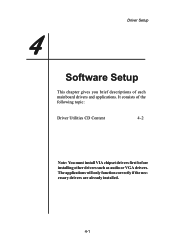
The applications will only function correctly if the necessary drivers are already installed. 4-1 4 Driver Setup Software Setup This chapter gives you brief descriptions of the following topic: Driver Utilities CD Content 4-2 Note: You must install VIA chipset drivers first before installing other drivers such as audio or VGA drivers. It consists of each mainboard drivers and applications.
The applications will only function correctly if the necessary drivers are already installed. 4-1 4 Driver Setup Software Setup This chapter gives you brief descriptions of the following topic: Driver Utilities CD Content 4-2 Note: You must install VIA chipset drivers first before installing other drivers such as audio or VGA drivers. It consists of each mainboard drivers and applications.
User Manual
Page 65
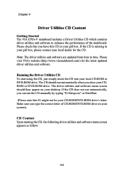
... latest updated driver utilities and software. Chapter 4 Driver Utilities CD Content Getting Started The VIA EPIA-V mainboard includes a Driver Utilities CD which contains driver utilities and software to time. The driver utilities and software menu screen should run the CD manually by typing "D:\Setup.exe" at Start\Run. (Please note that you close your CD-ROM/DVD-ROM drive's letter. Note: The driver utilities and software are updated from time to enhance the performance of CD-ROM/DVD-ROM drive on your local CD-ROM or DVD-ROM drive.
... latest updated driver utilities and software. Chapter 4 Driver Utilities CD Content Getting Started The VIA EPIA-V mainboard includes a Driver Utilities CD which contains driver utilities and software to time. The driver utilities and software menu screen should run the CD manually by typing "D:\Setup.exe" at Start\Run. (Please note that you close your CD-ROM/DVD-ROM drive's letter. Note: The driver utilities and software are updated from time to enhance the performance of CD-ROM/DVD-ROM drive on your local CD-ROM or DVD-ROM drive.

