User Manual
Page 3
...equipment has been tested and found to comply with FCC Standard For Home or Office Use iii Operation of the FCC rules. VIA EPIA-M Mini-ITX Mainboard Tested to comply with the limits for compliance could void the user's authority to cause harmful interference, in which case ... residential area is operated in order to comply with the instruction manual, may cause harmful interference to correct the interference at his own expense. power cord, if any, must be required to radio communications. Notice 2 Shielded interface cables and A.C. This equipment generates, uses and can radiate...
...equipment has been tested and found to comply with FCC Standard For Home or Office Use iii Operation of the FCC rules. VIA EPIA-M Mini-ITX Mainboard Tested to comply with the limits for compliance could void the user's authority to cause harmful interference, in which case ... residential area is operated in order to comply with the instruction manual, may cause harmful interference to correct the interference at his own expense. power cord, if any, must be required to radio communications. Notice 2 Shielded interface cables and A.C. This equipment generates, uses and can radiate...

User Manual
Page 5
...this equipment on a reliable flat surface before inserting any add-on the enclosure are for future reference. 3. Do not place anything over the power cord. 8. All cautions and warnings on it work according to User's Manual. • The equipment has dropped and damaged • If ...ENVIRONMENT UNCONDITIONED, STORAGE TEMPERATURE ABOVE 600 C (1400F), IT MAY DAMAGE THE EQUIPMENT. The openings on card or module. 9. Always unplug the power cord before setting it up. 5. CAUTION: Explosion or serious damage may occur if the battery is damaged • Liquid has penetrated into ...
...this equipment on a reliable flat surface before inserting any add-on the enclosure are for future reference. 3. Do not place anything over the power cord. 8. All cautions and warnings on it work according to User's Manual. • The equipment has dropped and damaged • If ...ENVIRONMENT UNCONDITIONED, STORAGE TEMPERATURE ABOVE 600 C (1400F), IT MAY DAMAGE THE EQUIPMENT. The openings on card or module. 9. Always unplug the power cord before setting it up. 5. CAUTION: Explosion or serious damage may occur if the battery is damaged • Liquid has penetrated into ...

User Manual
Page 7
Contents Specifications 1-1 Mainboard Specifications 1-2 Mainboard Layout 1-4 Connectors Guide 1-5 Installation 2-1 CPU 2-2 The VIA C3™ E-Series Processor 2-2 The VIA Eden Processor 2-3 Memory Installation 2-4 SDRAM Module Installation Procedures 2-4 Available SDRAM Configurations 2-5 Power Supply 2-6 ATX 20-Pin Power Connector: ATXPWR 2-6 Back Panel 2-7 Mouse Connector: JMS1 2-7 Keyboard Connector: JKB1 2-7 USB Port Connectors 2-8 RJ-45 NIC Port 2-8 Parallel Port Connector...
Contents Specifications 1-1 Mainboard Specifications 1-2 Mainboard Layout 1-4 Connectors Guide 1-5 Installation 2-1 CPU 2-2 The VIA C3™ E-Series Processor 2-2 The VIA Eden Processor 2-3 Memory Installation 2-4 SDRAM Module Installation Procedures 2-4 Available SDRAM Configurations 2-5 Power Supply 2-6 ATX 20-Pin Power Connector: ATXPWR 2-6 Back Panel 2-7 Mouse Connector: JMS1 2-7 Keyboard Connector: JKB1 2-7 USB Port Connectors 2-8 RJ-45 NIC Port 2-8 Parallel Port Connector...

User Manual
Page 8
... (J12 2-14 Floppy Disk Drive Connector: FDD 2-14 Jumpers 2-15 Clear CMOS Jumper: CLEAR_CMOS 2-15 Host Frequency Select (J13 2-16 Auto Reboot Function Setting (J2 2-17 RCA Video or S/PDIF Select (J11 2-17 Slots 2-18 PCI Slots 2-18 PCI Interrupt ...Keys 3-2 Getting Help 3-3 The Main Menu 3-4 Standard CMOS Features 3-6 Advanced BIOS Features 3-8 Advanced Chipset Features 3-11 Integrated Peripherals 3-13 Power Management Setup 3-16 PNP/PCI Configurations 3-21 PC Health Status 3-23 Frequency/Voltage Control 3-24 Load Fail-Safe Defaults 3-25 Load Optimized Defaults 3-26 Set ...
... (J12 2-14 Floppy Disk Drive Connector: FDD 2-14 Jumpers 2-15 Clear CMOS Jumper: CLEAR_CMOS 2-15 Host Frequency Select (J13 2-16 Auto Reboot Function Setting (J2 2-17 RCA Video or S/PDIF Select (J11 2-17 Slots 2-18 PCI Slots 2-18 PCI Interrupt ...Keys 3-2 Getting Help 3-3 The Main Menu 3-4 Standard CMOS Features 3-6 Advanced BIOS Features 3-8 Advanced Chipset Features 3-11 Integrated Peripherals 3-13 Power Management Setup 3-16 PNP/PCI Configurations 3-21 PC Health Status 3-23 Frequency/Voltage Control 3-24 Load Fail-Safe Defaults 3-25 Load Optimized Defaults 3-26 Set ...
User Manual
Page 10
The mainboard comes with an embedded VIA Processor, boasting ultra low power consumption and cool, quiet operation. 1 Specifications Specifications The ultra-compact and highly intergrated VIA EPIA-V Mini-ITX Mainboard is the smallest form factor mainboard specification available today, developed by VIA Technologies, Inc as part of FlexATX mainboard form factor. The VIA EPIA-V MiniITX mainboard enables the...
The mainboard comes with an embedded VIA Processor, boasting ultra low power consumption and cool, quiet operation. 1 Specifications Specifications The ultra-compact and highly intergrated VIA EPIA-V Mini-ITX Mainboard is the smallest form factor mainboard specification available today, developed by VIA Technologies, Inc as part of FlexATX mainboard form factor. The VIA EPIA-V MiniITX mainboard enables the...
User Manual
Page 12
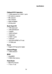
...; 1 RJ45 LAN port • 1 Serial port • 2 USB 1.1 ports • 1 VGA port • 1 RCA port (S/PDIF or TV out) • 1 S-Video port Power • Supports ATX type power supply Onboard Floppy • 1 FDD connector BIOS • Award BIOS • 2/4Mbit flash memory Form Factor • Mini-ITX (4 layers) • 17 cm x 17 cm 1-3 Specifications
...; 1 RJ45 LAN port • 1 Serial port • 2 USB 1.1 ports • 1 VGA port • 1 RCA port (S/PDIF or TV out) • 1 S-Video port Power • Supports ATX type power supply Onboard Floppy • 1 FDD connector BIOS • Award BIOS • 2/4Mbit flash memory Form Factor • Mini-ITX (4 layers) • 17 cm x 17 cm 1-3 Specifications
User Manual
Page 13
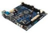
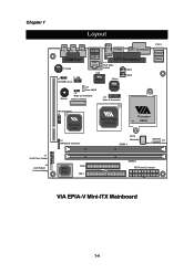
... South Bridge VT8231 J5 FIR Module Connector North Bridge VT8601A Processor EBGA Clock Generator DIMM 1 J13 Host Frequency Select BIOS ROM FDD IDE 1 DIMM 2 ATX Power Connector VIA EPIA-V Mini-ITX Mainboard 1-4
... South Bridge VT8231 J5 FIR Module Connector North Bridge VT8601A Processor EBGA Clock Generator DIMM 1 J13 Host Frequency Select BIOS ROM FDD IDE 1 DIMM 2 ATX Power Connector VIA EPIA-V Mini-ITX Mainboard 1-4
User Manual
Page 14
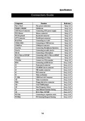
Connectors Guide Specifications Component Fan 1, Fan 2 DIMM1, DIMM2 ATX Power Connector PS/2 Mouse PS/2 Keyboard LPT Connector RJ-45 Port USB 0, USB 1 COM Port ...J3 J7 J5 J6 J8 F_USB J12 FDD J10 J13 J2 J11 PCI Slot PCI IRQ Function Fan power connectors DIMM slot Connecting ATX power supply Mouse connector Keyboard connector Parallel port connector Connecting to a LAN Connecting to USB devices COM port... p. 2-9 See p. 2-10 See p. 2-11 See p. 2-11 See p. 2-12 See p. 2-12 See p. 2-13 See p. 2-13 See p. 2-14 See p. 2-14 See p. 2-15 See p. 2-16 See p. 2-17 See p. 2-17 See p. 2-18 See p. 2-19 1-5
Connectors Guide Specifications Component Fan 1, Fan 2 DIMM1, DIMM2 ATX Power Connector PS/2 Mouse PS/2 Keyboard LPT Connector RJ-45 Port USB 0, USB 1 COM Port ...J3 J7 J5 J6 J8 F_USB J12 FDD J10 J13 J2 J11 PCI Slot PCI IRQ Function Fan power connectors DIMM slot Connecting ATX power supply Mouse connector Keyboard connector Parallel port connector Connecting to a LAN Connecting to USB devices COM port... p. 2-9 See p. 2-10 See p. 2-11 See p. 2-11 See p. 2-12 See p. 2-12 See p. 2-13 See p. 2-13 See p. 2-14 See p. 2-14 See p. 2-15 See p. 2-16 See p. 2-17 See p. 2-17 See p. 2-18 See p. 2-19 1-5

User Manual
Page 15
... information about hardware setup procedures. The components can be damaged by static electricity. This chapter contains the following topics: Central Processing Unit (CPU) Memory Installation Power Supply Back Panel Connectors Jumpers Slots PCI Interrupt Request Routing 2-2 2-4 2-6 2-7 2-10 2-15 2-18 2-19 2-1
... information about hardware setup procedures. The components can be damaged by static electricity. This chapter contains the following topics: Central Processing Unit (CPU) Memory Installation Power Supply Back Panel Connectors Jumpers Slots PCI Interrupt Request Routing 2-2 2-4 2-6 2-7 2-10 2-15 2-18 2-19 2-1
User Manual
Page 16
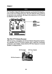
Chapter 2 CPU The VIA EPIA-V Mini-ITX Mainboard includes an embedded VIA Eden Processor or VIA C3™ E-Series Processor. Ensure that the CPU Fan Connector is correctly installed, as displayed below. CPU Fan Cable CPU Fan / Heatsink CPU ... connectors (Fan 1 & Fan 2) are provided on the mainboard, allowing for the connection of a CPU fan and an additional system case fan. The VIA C3™ E-Series Processor With low power consumption and advanced thermal dissipation properties, the embedded VIA C3™ E-Series requires only a small fan to guarantee performance and reliability.
Chapter 2 CPU The VIA EPIA-V Mini-ITX Mainboard includes an embedded VIA Eden Processor or VIA C3™ E-Series Processor. Ensure that the CPU Fan Connector is correctly installed, as displayed below. CPU Fan Cable CPU Fan / Heatsink CPU ... connectors (Fan 1 & Fan 2) are provided on the mainboard, allowing for the connection of a CPU fan and an additional system case fan. The VIA C3™ E-Series Processor With low power consumption and advanced thermal dissipation properties, the embedded VIA C3™ E-Series requires only a small fan to guarantee performance and reliability.

User Manual
Page 17
The VIA Eden Processor requires only a heatsink, as shown below. CPU Heatsink Overclocking This motherboard is not recommended. Any attempt to support overclocking. specifications is not designed to operate beyond product specifications. 2-3 We do not guarantee the damages or risks caused by operation beyond product WARNING! Hardware Setup The VIA Eden Processor Providing ultra-low power consumption and advanced thermal dissipation properties, the VIA Eden Processor features a fanless design.
The VIA Eden Processor requires only a heatsink, as shown below. CPU Heatsink Overclocking This motherboard is not recommended. Any attempt to support overclocking. specifications is not designed to operate beyond product specifications. 2-3 We do not guarantee the damages or risks caused by operation beyond product WARNING! Hardware Setup The VIA Eden Processor Providing ultra-low power consumption and advanced thermal dissipation properties, the VIA Eden Processor features a fanless design.

User Manual
Page 20
...14 PS_ON 15 GND 16 GND 17 GND 18 NC 19 5V 20 5V 2-6 ATX 20-Pin Power Connector To connect the ATX power supply, make sure that all components are correctly aligned. Chapter 2 Power Supply The VIA EPIA-V Mini-ITX Mainboard requires an ATX power supply to ensure that ...no damage will be connected. Before inserting the power supply connector, always make...
...14 PS_ON 15 GND 16 GND 17 GND 18 NC 19 5V 20 5V 2-6 ATX 20-Pin Power Connector To connect the ATX power supply, make sure that all components are correctly aligned. Chapter 2 Power Supply The VIA EPIA-V Mini-ITX Mainboard requires an ATX power supply to ensure that ...no damage will be connected. Before inserting the power supply connector, always make...

User Manual
Page 25
Hardware Setup Front Panel Connector (J3) The J3 front panel connectors allow you to connect the Power Switch, Reset Switch, Power LED and HDD LED to the system case. 1 HDD LED Power Switch Reset 11 2 Power LED 12 CD-ROM Line In Connector (J7) The J7 internal CD-ROM Line In Connector allows you to connect and receive audio input from a device such as a CD-ROM. 1 L R GND 2-11
Hardware Setup Front Panel Connector (J3) The J3 front panel connectors allow you to connect the Power Switch, Reset Switch, Power LED and HDD LED to the system case. 1 HDD LED Power Switch Reset 11 2 Power LED 12 CD-ROM Line In Connector (J7) The J7 internal CD-ROM Line In Connector allows you to connect and receive audio input from a device such as a CD-ROM. 1 L R GND 2-11

User Manual
Page 27
Hardware Setup Wake On Modem Connector (J8) This connector (J8) allows you to a modem with the Wake On Modem function. The connector will power up the system when a signal is received through the modem. 1 +5V_SB GND WOM USB Port 2&3 Connector (F_USB) This connector allows you to connect to connect ...
Hardware Setup Wake On Modem Connector (J8) This connector (J8) allows you to a modem with the Wake On Modem function. The connector will power up the system when a signal is received through the modem. 1 +5V_SB GND WOM USB Port 2&3 Connector (F_USB) This connector allows you to connect to connect ...
User Manual
Page 29
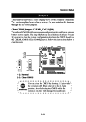
..., use of jumpers to the 2-3 pin position. Clear CMOS Jumper: CLEAR_CMOS (J10) The onboard CMOS RAM stores system configuration data and has an onboard battery power supply. system is off.
..., use of jumpers to the 2-3 pin position. Clear CMOS Jumper: CLEAR_CMOS (J10) The onboard CMOS RAM stores system configuration data and has an onboard battery power supply. system is off.

User Manual
Page 31
For S/ PDIF out, short 3-4. 31 42 1-2: RCA Video 3-4: S/PDIF 2-17 For TV-out composite function, please short 1-2. When enabled, the system will automatically reboot in the event it of sudden power outage. 1 1-2: Disable 2-3: Enable RCA Video or S/PDIF Select (J11) Users can select either RCA Video or S/PDIF as the enabled function on the dual-purpose port. Hardware Setup Auto Reboot Function Setting (J2) This jumper enables or disables the Auto Reboot Function Setting.
For S/ PDIF out, short 3-4. 31 42 1-2: RCA Video 3-4: S/PDIF 2-17 For TV-out composite function, please short 1-2. When enabled, the system will automatically reboot in the event it of sudden power outage. 1 1-2: Disable 2-3: Enable RCA Video or S/PDIF Select (J11) Users can select either RCA Video or S/PDIF as the enabled function on the dual-purpose port. Hardware Setup Auto Reboot Function Setting (J2) This jumper enables or disables the Auto Reboot Function Setting.
User Manual
Page 32
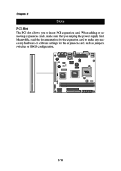
Chapter 2 Slots PCI Slot The PCI slot allows you to make sure that you unplug the power supply first. When adding or removing expansion cards, make any necessary hardware or software settings for the expansion card to insert PCI expansion card. Meanwhile, read the documentation for the expansion card, such as jumpers, switches or BIOS configuration. 2-18
Chapter 2 Slots PCI Slot The PCI slot allows you to make sure that you unplug the power supply first. When adding or removing expansion cards, make any necessary hardware or software settings for the expansion card to insert PCI expansion card. Meanwhile, read the documentation for the expansion card, such as jumpers, switches or BIOS configuration. 2-18

User Manual
Page 34
It consists of BIOS setup functions. 3 BIOS Setup BIOS Setup This chapter gives you detailed explaination of the following topics: Entering Setup Control Keys Getting Help The Main Menu Standard CMOS Features Advanced BIOS Features Advanced Chipset Features Integrated Peripherals Power Management Setup PNP/PCI Configurations PC Health Status Frequency/Voltage Control Load Fail-Safe Defaults Load Optimized Defaults Set Supervisor/User Password Save & Exit Setup Exit Without Saving 3-2 3-2 3-3 3-4 3-6 3-8 3-11 3-13 3-16 3-21 3-23 3-24 3-25 3-26 3-27 3-29 3-30 3-1
It consists of BIOS setup functions. 3 BIOS Setup BIOS Setup This chapter gives you detailed explaination of the following topics: Entering Setup Control Keys Getting Help The Main Menu Standard CMOS Features Advanced BIOS Features Advanced Chipset Features Integrated Peripherals Power Management Setup PNP/PCI Configurations PC Health Status Frequency/Voltage Control Load Fail-Safe Defaults Load Optimized Defaults Set Supervisor/User Password Save & Exit Setup Exit Without Saving 3-2 3-2 3-3 3-4 3-6 3-8 3-11 3-13 3-16 3-21 3-23 3-24 3-25 3-26 3-27 3-29 3-30 3-1

User Manual
Page 35
Chapter 3 Entering Setup Power on the computer and press DEL straight away to the main menu from a submenu Increase the numeric value or make changes Decrease the numeric value ...
Chapter 3 Entering Setup Power on the computer and press DEL straight away to the main menu from a submenu Increase the numeric value or make changes Decrease the numeric value ...

User Manual
Page 37
... system. Standard CMOS Features Use this menu to set the PnP and PCI configurations. 3-4 PnP/PCI Configurations Use this menu to set basic system configurations. Power Management Setup Use this menu to accept or enter the submenu. Use arrow keys to select the items and press to set onboard...
... system. Standard CMOS Features Use this menu to set the PnP and PCI configurations. 3-4 PnP/PCI Configurations Use this menu to set basic system configurations. Power Management Setup Use this menu to accept or enter the submenu. Use arrow keys to select the items and press to set onboard...