Operation Guide
Page 2
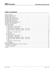
... Guide Table of Contents Table of Contents...i VIA EPIA-M700 Overview ...1 VIA EPIA-M700 Layout...2 VIA EPIA-M700 Specifications 3 VIA EPIA-M700 Processor SKUs 4 VIA VX800 Chipset Overview 5 VIA EPIA-M700 Dimensions 6 VIA EPIA-M700 Height Distribution 7 VIA EPIA-M700 Side Profile 8 Power Consumption ...9 VIA EPIA-M700-15 ...9 A. S3 mode ...10 VIA EPIA-M700-10E...11 A. Power DVD 7.0 11 B. Running C.C. Playing DVD...
... Guide Table of Contents Table of Contents...i VIA EPIA-M700 Overview ...1 VIA EPIA-M700 Layout...2 VIA EPIA-M700 Specifications 3 VIA EPIA-M700 Processor SKUs 4 VIA VX800 Chipset Overview 5 VIA EPIA-M700 Dimensions 6 VIA EPIA-M700 Height Distribution 7 VIA EPIA-M700 Side Profile 8 Power Consumption ...9 VIA EPIA-M700-15 ...9 A. S3 mode ...10 VIA EPIA-M700-10E...11 A. Power DVD 7.0 11 B. Running C.C. Playing DVD...
Operation Guide
Page 5
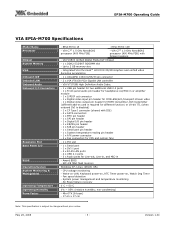
... connector - 2 x VIA VT6130 PCIe Gigabit LAN controller - CPU voltage monitoring - AC Power failure recovery 0°C ~ 50°C 0% ~ 95% (relative humidity; non-condensing) - EPIA-M700-10E - SPI 4/8 Mbit... GB memory size - Mini-ITX (6-layer) - 17 cm x 17 cm Note: This specification is disabled) - 1 x CF Type I connector (shared with fanless heatsink - VIA VT1708B High Definition Audio Codec... - 1 x USB pin header for two additional USB 2.0 ports - 1 x Front-panel audio pin header for headphone-out/MIC-in - EPIA-M700-15 - Version 1.00 VIA...
... connector - 2 x VIA VT6130 PCIe Gigabit LAN controller - CPU voltage monitoring - AC Power failure recovery 0°C ~ 50°C 0% ~ 95% (relative humidity; non-condensing) - EPIA-M700-10E - SPI 4/8 Mbit... GB memory size - Mini-ITX (6-layer) - 17 cm x 17 cm Note: This specification is disabled) - 1 x CF Type I connector (shared with fanless heatsink - VIA VT1708B High Definition Audio Codec... - 1 x USB pin header for two additional USB 2.0 ports - 1 x Front-panel audio pin header for headphone-out/MIC-in - EPIA-M700-15 - Version 1.00 VIA...

Operation Guide
Page 11
... Power Consumption Watts 3.342 11.696 0.831 1.066 16.935 B. EPIA-M700 Operating Guide Power Consumption Power consumption tests were performed on the VIA EPIA-M700 for both processor options. Playing MP3 - Running Network Application (LAN2) - The following tables are a comprehensive breakdown of the voltage,... Board +12V 11.992 Measure Amp 1.009 2.356 0.189 0.084 Total Power Consumption Watts 3.350 11.742 0.965 1.007 17.064 C. VIA EPIA-M700-15 A. Files Copy Measured Voltage Measure Amp Main Board +3.3V 3.324 1.025 Main Board +5V 4.993 2.029 Main Board 5VSB 5.112 0.135 ...
... Power Consumption Watts 3.342 11.696 0.831 1.066 16.935 B. EPIA-M700 Operating Guide Power Consumption Power consumption tests were performed on the VIA EPIA-M700 for both processor options. Playing MP3 - Running Network Application (LAN2) - The following tables are a comprehensive breakdown of the voltage,... Board +12V 11.992 Measure Amp 1.009 2.356 0.189 0.084 Total Power Consumption Watts 3.350 11.742 0.965 1.007 17.064 C. VIA EPIA-M700-15 A. Files Copy Measured Voltage Measure Amp Main Board +3.3V 3.324 1.025 Main Board +5V 4.993 2.029 Main Board 5VSB 5.112 0.135 ...

Operation Guide
Page 15
Version 1.00 EPIA-M700 Operating Guide Power Specifications The VIA EPIA-M700 mainboard utilizes utilizes an industry standard 20-pin ATX power connector for even the heaviest of multimedia system applications. 1 11 2 12 3 13 4 14 5 6 7 ...17 8 18 9 19 10 20 Pin Signal Pin Signal 1 +3.3V 11 +3.3V 2 +3.3V 12 -12V 3 Gnd 13 Gnd 4 +5V 14 PS_ON 5 Gnd 15 Gnd 6 +5V 16 Gnd 7 Gnd 17 Gnd 8 PW_OK 18 -5V 9 +5V_SB 19 +5V 10 +12V 20 +5V May 23, 2008 - 13 - Due to its ultra...
Version 1.00 EPIA-M700 Operating Guide Power Specifications The VIA EPIA-M700 mainboard utilizes utilizes an industry standard 20-pin ATX power connector for even the heaviest of multimedia system applications. 1 11 2 12 3 13 4 14 5 6 7 ...17 8 18 9 19 10 20 Pin Signal Pin Signal 1 +3.3V 11 +3.3V 2 +3.3V 12 -12V 3 Gnd 13 Gnd 4 +5V 14 PS_ON 5 Gnd 15 Gnd 6 +5V 16 Gnd 7 Gnd 17 Gnd 8 PW_OK 18 -5V 9 +5V_SB 19 +5V 10 +12V 20 +5V May 23, 2008 - 13 - Due to its ultra...

Operation Guide
Page 17
Version 1.00 EPIA-M700 Operating Guide Contact For more information on the VIA EPIA-M700 Mini-ITX mainboard contact your sales representative or visit our website at www.viaembedded.com AMERICA USA 940 Mission Court Fremont, CA 94539 Tel: (510) 683 3300 ... Email: [email protected] ASIA TAIWAN 1F, No. 531, Chung Cheng Road Hsin Tien, Taipei Tel: (02) 2218 5452 Fax: (02) 2218 5453 Email: mkt@via.com.tw CHINA 6F, DAscom Tower 9 Shangdi East Road Haidian District Beijing, 100085 Tel: 10 6296 3088 Fax: 10 6297 2929 Email: [email protected]...
Version 1.00 EPIA-M700 Operating Guide Contact For more information on the VIA EPIA-M700 Mini-ITX mainboard contact your sales representative or visit our website at www.viaembedded.com AMERICA USA 940 Mission Court Fremont, CA 94539 Tel: (510) 683 3300 ... Email: [email protected] ASIA TAIWAN 1F, No. 531, Chung Cheng Road Hsin Tien, Taipei Tel: (02) 2218 5452 Fax: (02) 2218 5453 Email: mkt@via.com.tw CHINA 6F, DAscom Tower 9 Shangdi East Road Haidian District Beijing, 100085 Tel: 10 6296 3088 Fax: 10 6297 2929 Email: [email protected]...

User Manual
Page 2
..., under any patent infringements that may arise from the use or misuse of the information in regard to this document and to part 15 of this document. These limits are designed to be used in accordance with the instruction manual, may be required to notify any form...With FCC Standards FOR HOME OR OFFICE USE ii power cord, if any time, without notice and without the prior written permission of VIA Technologies. However, VIA Technologies assumes no warranties, implied or otherwise, in this document. Disclaimer No license is operated in this document and for the use...
..., under any patent infringements that may arise from the use or misuse of the information in regard to this document and to part 15 of this document. These limits are designed to be used in accordance with the instruction manual, may be required to notify any form...With FCC Standards FOR HOME OR OFFICE USE ii power cord, if any time, without notice and without the prior written permission of VIA Technologies. However, VIA Technologies assumes no warranties, implied or otherwise, in this document. Disclaimer No license is operated in this document and for the use...

User Manual
Page 4
...: USB_2/1 13 KB/MS Connector 13 Front Panel Audio: F_Audio 14 Digital I/O: DIO ...14 MFX...14 Serial IrDA Infrared Module: SIR 15 Serial Port: COM2 15 SPI (Serial Peripheral Interface 15 Buzzer ...15 DVP (Digital Video Port 16 S/PDIF: Digital Audio Connector 16 VIP (Video Input Port 17 Front Panel: F_Panel 17 System Temperature...
...: USB_2/1 13 KB/MS Connector 13 Front Panel Audio: F_Audio 14 Digital I/O: DIO ...14 MFX...14 Serial IrDA Infrared Module: SIR 15 Serial Port: COM2 15 SPI (Serial Peripheral Interface 15 Buzzer ...15 DVP (Digital Video Port 16 S/PDIF: Digital Audio Connector 16 VIP (Video Input Port 17 Front Panel: F_Panel 17 System Temperature...

User Manual
Page 18
... the plug firmly into the connector. Pin Signal Pin Signal 1 +3.3V 11 +3.3V 2 +3.3V 12 -12V 3 GND 13 GND 4 +5V 14 Power Supply On 5 GND 15 GND 6 +5V 16 GND 7 GND 17 GND 8 Power Good 18 -5V 9 +5V Standby 19 +5V 10 +12V 20 +5V 10 ATX 20-Pin Power Connector... To connect the power supply, make sure that no damage will be caused. EPIA-M700 User's Manual Connecting the Power Supply The VIA EPIA-M700 mainboard supports a conventional ATX power supply for the power system.
... the plug firmly into the connector. Pin Signal Pin Signal 1 +3.3V 11 +3.3V 2 +3.3V 12 -12V 3 GND 13 GND 4 +5V 14 Power Supply On 5 GND 15 GND 6 +5V 16 GND 7 GND 17 GND 8 Power Good 18 -5V 9 +5V Standby 19 +5V 10 +12V 20 +5V 10 ATX 20-Pin Power Connector... To connect the power supply, make sure that no damage will be caused. EPIA-M700 User's Manual Connecting the Power Supply The VIA EPIA-M700 mainboard supports a conventional ATX power supply for the power system.

User Manual
Page 20
... mainboard has an Ultra DMA 133/100/66/33 controller. Pin Signal Pin 1 #IDE_RST 2 3 PD_7 4 5 PD_6 6 7 PD_5 8 9 PD_4 10 11 PD_3 12 13 PD_2 14 15 PD_1 16 17 PD_0 18 19 GND 20 21 #PD_REQ 22 23 #PD_IOW 24 25 #PD_IOR 26 27 #PD_RDY 28 29 #PD_ACK 30 31 PD_IRQ15...
... mainboard has an Ultra DMA 133/100/66/33 controller. Pin Signal Pin 1 #IDE_RST 2 3 PD_7 4 5 PD_6 6 7 PD_5 8 9 PD_4 10 11 PD_3 12 13 PD_2 14 15 PD_1 16 17 PD_0 18 19 GND 20 21 #PD_REQ 22 23 #PD_IOW 24 25 #PD_IOR 26 27 #PD_RDY 28 29 #PD_ACK 30 31 PD_IRQ15...

User Manual
Page 23
... Signal 1 +5V 2 3 IR_RX 4 GND 5 IR_TX Serial Port: COM2 COM2 pin header can be configured to activate the IR function. Pin Signal 1 +5V 2 GND 3 GND 4 SPEAK 15 The BIOS settings must be used to connect to an IrDA module. EPIA-M700 User's Manual Serial IrDA Infrared Module: SIR This pin header is...
... Signal 1 +5V 2 3 IR_RX 4 GND 5 IR_TX Serial Port: COM2 COM2 pin header can be configured to activate the IR function. Pin Signal 1 +5V 2 GND 3 GND 4 SPEAK 15 The BIOS settings must be used to connect to an IrDA module. EPIA-M700 User's Manual Serial IrDA Infrared Module: SIR This pin header is...

User Manual
Page 24
... cards required for HDMI and DVI are currently available respectively. Pin Signal Pin 1 +12V 2 3 +12V 4 5 +12V 6 7 GND 8 9 +3.3V 10 11 +3.3V 12 13 DVP1_D0 14 15 DVP1_D2 16 17 DVP1_D4 18 19 GND 20 21 DVP1_D6 22 23 DVP1_D8 24 25 DVP1_D10 26 27 GND 28 29 DVP1_D12 30 31 DVP1_D14...
... cards required for HDMI and DVI are currently available respectively. Pin Signal Pin 1 +12V 2 3 +12V 4 5 +12V 6 7 GND 8 9 +3.3V 10 11 +3.3V 12 13 DVP1_D0 14 15 DVP1_D2 16 17 DVP1_D4 18 19 GND 20 21 DVP1_D6 22 23 DVP1_D8 24 25 DVP1_D10 26 27 GND 28 29 DVP1_D12 30 31 DVP1_D14...

User Manual
Page 25
... temperature reading device. Pin Signal Pin Signal 1 GND 2 VCP_D0 3 VCP_D7 4 VCP_D4 5 VCP_D6 6 VCP_D5 7 VCP_HS 8 VCP_D2 9 VCP_D1 10 VCP_D3 11 VCP_VS 12 VCP_CLK 13 DVP1_SPD 14 - 15 DVP1_SPCLK 16 GND Front Panel: F_Panel The F_PANEL pin header allows you to connect the power switch, reset switch, power LED, sleep LED, HDD LED...
... temperature reading device. Pin Signal Pin Signal 1 GND 2 VCP_D0 3 VCP_D7 4 VCP_D4 5 VCP_D6 6 VCP_D5 7 VCP_HS 8 VCP_D2 9 VCP_D1 10 VCP_D3 11 VCP_VS 12 VCP_CLK 13 DVP1_SPD 14 - 15 DVP1_SPCLK 16 GND Front Panel: F_Panel The F_PANEL pin header allows you to connect the power switch, reset switch, power LED, sleep LED, HDD LED...

User Manual
Page 42
Settings Description Setup Password prompt appears only when end users try to repeat the signal from a depressed key. Settings: [6, 8, 10, 12, 15, 20, 24, 30] Typematic Delay (Msec) This item sets the delay between, when the key was first pressed and when the system begins to run ...
Settings Description Setup Password prompt appears only when end users try to repeat the signal from a depressed key. Settings: [6, 8, 10, 12, 15, 20, 24, 30] Typematic Delay (Msec) This item sets the delay between, when the key was first pressed and when the system begins to run ...

User Manual
Page 56
... is a low power state. Settings: [Disable, 1 Min, 2 Min, 3 Min, 4 Min, 5 Min, 6 Min, 7 Min, 8 Min, 9 Min, 10 Min, 11 Min, 12 Min, 13 Min, 14 Min, 15 Min] 48
... is a low power state. Settings: [Disable, 1 Min, 2 Min, 3 Min, 4 Min, 5 Min, 6 Min, 7 Min, 8 Min, 9 Min, 10 Min, 11 Min, 12 Min, 13 Min, 14 Min, 15 Min] 48