
Operation Guide
Page 3
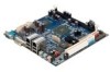
... MHz DDR2 memory. The VIA EPIA-M700 provides support for high fidelity audio with a full range of Mini-ITX chassis as well as FlexATX and MicroATX enclosures and power supplies. The VIA EPIA-M700 is fully compatible with 2D/3D graphics and video accelerators for entry level systems in embedded and productivity applications. Version 1.00 The VIA C7® NanoBGA2 processor is a compact native x86 mainboard optimized for...
... MHz DDR2 memory. The VIA EPIA-M700 provides support for high fidelity audio with a full range of Mini-ITX chassis as well as FlexATX and MicroATX enclosures and power supplies. The VIA EPIA-M700 is fully compatible with 2D/3D graphics and video accelerators for entry level systems in embedded and productivity applications. Version 1.00 The VIA C7® NanoBGA2 processor is a compact native x86 mainboard optimized for...
Operation Guide
Page 5
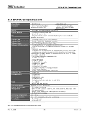
...to 2 GB memory size - May 23, 2008 - 3 - Version 1.00 Award BIOS - CPU voltage monitoring - SPI 4/8 Mbit flash memory Windows XP, Linux, WinCE, XPe - Integrated VIA Chrome9™ HC3 DX9 3D/2D Graphics and unified video decoding acceleration - 1 x UltraDMA 133/100/66/33 pin connector - 2 x VIA VT6130 PCIe Gigabit LAN controller - non-condensing) - EPIA-M700 Operating Guide VIA EPIA-M700 Specifications Model Name Processor Chipset System Memory VGA Onboard IDE Onboard LAN Onboard Audio Onboard I/O Connectors Expansion Slot Back Panel I port - 2 x RJ-45 LAN ports...
...to 2 GB memory size - May 23, 2008 - 3 - Version 1.00 Award BIOS - CPU voltage monitoring - SPI 4/8 Mbit flash memory Windows XP, Linux, WinCE, XPe - Integrated VIA Chrome9™ HC3 DX9 3D/2D Graphics and unified video decoding acceleration - 1 x UltraDMA 133/100/66/33 pin connector - 2 x VIA VT6130 PCIe Gigabit LAN controller - non-condensing) - EPIA-M700 Operating Guide VIA EPIA-M700 Specifications Model Name Processor Chipset System Memory VGA Onboard IDE Onboard LAN Onboard Audio Onboard I/O Connectors Expansion Slot Back Panel I port - 2 x RJ-45 LAN ports...

User Manual
Page 3
.... Caution: Only use the appropriate battery specified for future reference. The openings on it work according to the power inlet. Make sure the voltage of the power source and adjust properly 110/220V before inserting any of breakage. Do not reuse, recharge, or reheat an old battery. Always unplug the power cord before connecting the equipment to User's Manual. Never pour...
.... Caution: Only use the appropriate battery specified for future reference. The openings on it work according to the power inlet. Make sure the voltage of the power source and adjust properly 110/220V before inserting any of breakage. Do not reuse, recharge, or reheat an old battery. Always unplug the power cord before connecting the equipment to User's Manual. Never pour...

User Manual
Page 4
... Safety Instructions ...iii Table of Contents...iv CCChhhaaapppttteeerrr111 Specifications 1 Mainboard Specifications 2 Mainboard Layout ...4 Back Panel Layout ...6 CCChhhaaapppttteeerrr222 Installation ...7 CPU ...8 CPU Fan and System Fan: CPUFAN and SYSFAN 8 Memory Module Installation 9 Memory Slot: DDR2 DIMM 9 DDR2 SDRAM Module Installation Procedures 9 Available DDR2 SDRAM Configurations 9 Connecting the Power Supply 10 ATX 20-Pin Power Connector 10 Back Panel Ports ...11 COM (Serial) Port 11 DVI-I Port...11 RJ-45 LAN Ports...11 USB Ports...11 Audio Port...11 Connectors...12 IDE...
... Safety Instructions ...iii Table of Contents...iv CCChhhaaapppttteeerrr111 Specifications 1 Mainboard Specifications 2 Mainboard Layout ...4 Back Panel Layout ...6 CCChhhaaapppttteeerrr222 Installation ...7 CPU ...8 CPU Fan and System Fan: CPUFAN and SYSFAN 8 Memory Module Installation 9 Memory Slot: DDR2 DIMM 9 DDR2 SDRAM Module Installation Procedures 9 Available DDR2 SDRAM Configurations 9 Connecting the Power Supply 10 ATX 20-Pin Power Connector 10 Back Panel Ports ...11 COM (Serial) Port 11 DVI-I Port...11 RJ-45 LAN Ports...11 USB Ports...11 Audio Port...11 Connectors...12 IDE...

User Manual
Page 5
... Slots ...19 Peripheral Component Interconnect: PCI 19 PCI Interrupt Request Routing 19 Compact Flash Type I Connector: CF 19 CCChhhaaapppttteeerrr333 BIOS Setup...21 Entering the BIOS Setup Menu 22 Control Keys ...23 Navigating the BIOS Menus 24 Getting Help...25 Main Menu...26 Standard CMOS Features 26 Advanced BIOS Features 26 Advanced Chipset Features 26 Integrated Peripherals 26 Power Management Setup 26 PnP/PCI Configurations 26 PC Health Status 27 Frequency/Voltage Control 27 Load Optimized Defaults 27 Set Supervisor Password 27 Set User Password...
... Slots ...19 Peripheral Component Interconnect: PCI 19 PCI Interrupt Request Routing 19 Compact Flash Type I Connector: CF 19 CCChhhaaapppttteeerrr333 BIOS Setup...21 Entering the BIOS Setup Menu 22 Control Keys ...23 Navigating the BIOS Menus 24 Getting Help...25 Main Menu...26 Standard CMOS Features 26 Advanced BIOS Features 26 Advanced Chipset Features 26 Integrated Peripherals 26 Power Management Setup 26 PnP/PCI Configurations 26 PC Health Status 27 Frequency/Voltage Control 27 Load Optimized Defaults 27 Set Supervisor Password 27 Set User Password...

User Manual
Page 7
... by PCI Card 51 RTC Alarm Resume 51 Date (of Month)...51 Resume Time (hh : mm : ss 51 PnP/PCI Configurations 52 Init Display First ...52 PNP OS Installed 52 Reset Configuration Data 52 Resources Controlled By 53 PCI/VGA Palette Snoop 53 Assign IRQ for VGA 53 Assign IRQ for USB 53 Maximum Payload Size 53 PC Health Status...54 Frequency/Voltage Control 55 DRAM Frequency 55 DRAM Channel Mode 55...
... by PCI Card 51 RTC Alarm Resume 51 Date (of Month)...51 Resume Time (hh : mm : ss 51 PnP/PCI Configurations 52 Init Display First ...52 PNP OS Installed 52 Reset Configuration Data 52 Resources Controlled By 53 PCI/VGA Palette Snoop 53 Assign IRQ for VGA 53 Assign IRQ for USB 53 Maximum Payload Size 53 PC Health Status...54 Frequency/Voltage Control 55 DRAM Frequency 55 DRAM Channel Mode 55...
User Manual
Page 10
...-M700 User's Manual Mainboard Specifications CPU • VIA C7 1.0GHz / 1.5GHz NanoBGA2 processor Chipset • VIA VX800 advanced all-in-one system processor Graphics • Integrated VIA Chrome9™ HC DX9 3D/2D Graphics and Unified Video Decoding Accelerator Audio • VIA VT1708B High Definition Audio codec Memory • 1 x DDR2 667/533 DIMM slot (up to 2 GB) Expansion Slot • 1 x PCI slot IDE • 1 x UltraDMA 133/100/66/33 pin header LAN • 2 x VIA VT6130 PCIe Gigabit Ethernet Controllers Onboard I/O Connectors • 1 x USB pin header...
...-M700 User's Manual Mainboard Specifications CPU • VIA C7 1.0GHz / 1.5GHz NanoBGA2 processor Chipset • VIA VX800 advanced all-in-one system processor Graphics • Integrated VIA Chrome9™ HC DX9 3D/2D Graphics and Unified Video Decoding Accelerator Audio • VIA VT1708B High Definition Audio codec Memory • 1 x DDR2 667/533 DIMM slot (up to 2 GB) Expansion Slot • 1 x PCI slot IDE • 1 x UltraDMA 133/100/66/33 pin header LAN • 2 x VIA VT6130 PCIe Gigabit Ethernet Controllers Onboard I/O Connectors • 1 x USB pin header...
User Manual
Page 17
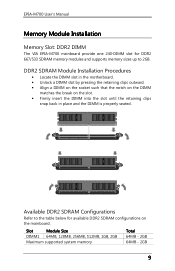
... User's Manual Memory Module Installation Memory Slot: DDR2 DIMM The VIA EPIA-M700 mainboard provide one 240-DIMM slot for DDR2 667/533 SDRAM memory modules and supports memory sizes up to the table below for available DDR2 SDRAM configurations on the slot. • Firmly insert the DIMM into the slot until the retaining clips snap back in place and the DIMM is properly seated. Slot Module Size...
... User's Manual Memory Module Installation Memory Slot: DDR2 DIMM The VIA EPIA-M700 mainboard provide one 240-DIMM slot for DDR2 667/533 SDRAM memory modules and supports memory sizes up to the table below for available DDR2 SDRAM configurations on the slot. • Firmly insert the DIMM into the slot until the retaining clips snap back in place and the DIMM is properly seated. Slot Module Size...

User Manual
Page 21
...: When the pin header is not in use. Therefore mainboard can be used to two additional USB 2.0 ports). EPIA-M700 User's Manual SATA Ports These next generation connectors support the thin SATA cables for primary internal storage devices. Please short pin 3&5, pin 4&6, pin 7&9 and pin 8&10. 13 The current SATA interface allows up to connect high-speed USB interface peripherals such as USB HDD, digital cameras, MP3 players, printers, modem and the like. Port 1 Port 2 USB Pin Connector: USB_2/1 The mainboard provides 4 USB ports and one USB pin header (allowing up...
...: When the pin header is not in use. Therefore mainboard can be used to two additional USB 2.0 ports). EPIA-M700 User's Manual SATA Ports These next generation connectors support the thin SATA cables for primary internal storage devices. Please short pin 3&5, pin 4&6, pin 7&9 and pin 8&10. 13 The current SATA interface allows up to connect high-speed USB interface peripherals such as USB HDD, digital cameras, MP3 players, printers, modem and the like. Port 1 Port 2 USB Pin Connector: USB_2/1 The mainboard provides 4 USB ports and one USB pin header (allowing up...

User Manual
Page 26
... the mainboard. To reset the CMOS settings, set the jumper on will explain how to pins 2 and 3 afterwards. Avoid clearing the CMOS while the system is on CLEAR_CMOS jumper default position. Clear CMOS Connector: CLEAR_CMOS1 The onboard CMOS RAM stores system configuration data and has an onboard battery power supply. Return the jumper to change the settings of the mainboard functions using the jumpers. The default value is Master. The default value is +3.3V. Setting 12 3 Normal Operation ON ON OFF Clear CMOS setting...
... the mainboard. To reset the CMOS settings, set the jumper on will explain how to pins 2 and 3 afterwards. Avoid clearing the CMOS while the system is on CLEAR_CMOS jumper default position. Clear CMOS Connector: CLEAR_CMOS1 The onboard CMOS RAM stores system configuration data and has an onboard battery power supply. Return the jumper to change the settings of the mainboard functions using the jumpers. The default value is Master. The default value is +3.3V. Setting 12 3 Normal Operation ON ON OFF Clear CMOS setting...

User Manual
Page 27
... "PCI & LAN" IRQ pins are typically connected to the PCI bus INT A# ~ INT D# pins as follows: PCI Slot Order 1 INT B# Order 2 INT C# Order 3 INT D# Order 4 INT A# Compact Flash Type I Connector: CF This CF connector allows you to insert PCI expansion card. PCI Interrupt Request Routing The IRQ (interrupt request line) are necessary. When adding or removing expansion card, unplug first the power supply. EPIA-M700 User's Manual Slots Peripheral Component Interconnect: PCI The PCI slot allows...
... "PCI & LAN" IRQ pins are typically connected to the PCI bus INT A# ~ INT D# pins as follows: PCI Slot Order 1 INT B# Order 2 INT C# Order 3 INT D# Order 4 INT A# Compact Flash Type I Connector: CF This CF connector allows you to insert PCI expansion card. PCI Interrupt Request Routing The IRQ (interrupt request line) are necessary. When adding or removing expansion card, unplug first the power supply. EPIA-M700 User's Manual Slots Peripheral Component Interconnect: PCI The PCI slot allows...

User Manual
Page 32
...-menu. AwardBIOS CMOS Setup Utility Standard CMOS Features Advanced BIOS Features Advanced Chipset Features Integrated Peripherals Power Management Setup PnP/PCI Configurations PC Health Status Frequency/Voltage Control Load Optimized Defaults Set Supervisor Password Set User Password Save & Exit Setup Exit Without Saving Esc : Quit F10 : Save & Exit Setup : Select Item Time, Date, Hard Disk Type... 24 EPIA-M700 User's Manual Navigating the BIOS Menus The main menu displays all the BIOS setup categories. To exit the sub-menu, press . Press to display the sub-menu. Sub-menu...
...-menu. AwardBIOS CMOS Setup Utility Standard CMOS Features Advanced BIOS Features Advanced Chipset Features Integrated Peripherals Power Management Setup PnP/PCI Configurations PC Health Status Frequency/Voltage Control Load Optimized Defaults Set Supervisor Password Set User Password Save & Exit Setup Exit Without Saving Esc : Quit F10 : Save & Exit Setup : Select Item Time, Date, Hard Disk Type... 24 EPIA-M700 User's Manual Navigating the BIOS Menus The main menu displays all the BIOS setup categories. To exit the sub-menu, press . Press to display the sub-menu. Sub-menu...

User Manual
Page 33
The help screen. 25 Press to exit the help screen displays the keys for using and navigating the BIOS setup. You can display this screen from any menu/sub-menu by pressing . EPIA-M700 User's Manual Getting Help The BIOS setup program provides a "General Help" screen.
The help screen. 25 Press to exit the help screen displays the keys for using and navigating the BIOS setup. You can display this screen from any menu/sub-menu by pressing . EPIA-M700 User's Manual Getting Help The BIOS setup program provides a "General Help" screen.

User Manual
Page 40
Settings Enabled Disabled Description Turns on hard disk boot sector virus protection Turns off CPU L1 & L2 cache Turns on the screen and alarm beep. CPU L1 & L2 Cache Settings Disabled Enabled Description Turns off hard disk boot sector virus protection Note: If this function is enabled and someone attempt to choose the VIRUS warning feature for DRAM > 64MB HDD S.M.A.R.T Capability Video BIOS Shadow Full Screen LOGO Show Summary Screen Show [Press Enter] [Press Enter] [Disabled] [Enabled] [Enabled] [Enabled] [CDROM] [Hard Disk] [LS120] [Enabled] [On] [Disabled] 6 250 [Setup] ...
Settings Enabled Disabled Description Turns on hard disk boot sector virus protection Turns off CPU L1 & L2 cache Turns on the screen and alarm beep. CPU L1 & L2 Cache Settings Disabled Enabled Description Turns off hard disk boot sector virus protection Note: If this function is enabled and someone attempt to choose the VIRUS warning feature for DRAM > 64MB HDD S.M.A.R.T Capability Video BIOS Shadow Full Screen LOGO Show Summary Screen Show [Press Enter] [Press Enter] [Disabled] [Enabled] [Enabled] [Enabled] [CDROM] [Hard Disk] [LS120] [Enabled] [On] [Disabled] 6 250 [Setup] ...

User Manual
Page 41
...10-key Typematic Rate Setting Enables "Typematic Rate" and "Typematic Delay" functions. Settings LS120 Hard Disk CDROM ZIP100 USB-FDD USB-ZIP USB-CDROM Legacy LAN VIA Networking Disabled Description Boot from LS-120 drive Boot from the HDD Boot from CDROM Boot from ATAPI ZIP drive Boot from USB Floppy drive Boot from USB ZIP drive Boot from USB CDROM Boot from network drive Boot from network drive Disable the boot device sequence Boot Other Device Enables the system to boot from the "First/Second/Third Boot Device" lists. Settings Description Disabled No alternate boot device allowed...
...10-key Typematic Rate Setting Enables "Typematic Rate" and "Typematic Delay" functions. Settings LS120 Hard Disk CDROM ZIP100 USB-FDD USB-ZIP USB-CDROM Legacy LAN VIA Networking Disabled Description Boot from LS-120 drive Boot from the HDD Boot from CDROM Boot from ATAPI ZIP drive Boot from USB Floppy drive Boot from USB ZIP drive Boot from USB CDROM Boot from network drive Boot from network drive Disable the boot device sequence Boot Other Device Enables the system to boot from the "First/Second/Third Boot Device" lists. Settings Description Disabled No alternate boot device allowed...

User Manual
Page 42
..., 1000] Security Option Selects whether the password is powered on the system. EPIA-M700 User's Manual Typematic Rate (Chars/Sec) This item sets the rate (characters/second) at which the system retrieves a signal from the depressed key. Settings: [Non-OS2, OS2] HDD S.M.A.R.T Capability Settings: [Disabled, Enabled] Video BIOS Shadow Enabled copies Video BIOS to run BIOS Setup MPS Version Control for OS Settings: [1.1, 1.4] OS Select for DRAM > 64MB Select OS2 only if you enter Setup.
..., 1000] Security Option Selects whether the password is powered on the system. EPIA-M700 User's Manual Typematic Rate (Chars/Sec) This item sets the rate (characters/second) at which the system retrieves a signal from the depressed key. Settings: [Non-OS2, OS2] HDD S.M.A.R.T Capability Settings: [Disabled, Enabled] Video BIOS Shadow Enabled copies Video BIOS to run BIOS Setup MPS Version Control for OS Settings: [1.1, 1.4] OS Select for DRAM > 64MB Select OS2 only if you enter Setup.

User Manual
Page 51
EPIA-M700 User's Manual Secondary Master UDMA Settings: [Disabled, Auto] Secondary Slave UDMA Settings: [Disabled, Auto] IDE HDD Block Mode Settings: [Disabled, Enabled] 43
EPIA-M700 User's Manual Secondary Master UDMA Settings: [Disabled, Auto] Secondary Slave UDMA Settings: [Disabled, Auto] IDE HDD Block Mode Settings: [Disabled, Enabled] 43

User Manual
Page 54
Settings: [Disabled, Enabled] USB 2.0 Controller Enable or disable Enhanced Host Controller Interface for Universal Serial Bus. USB Keyboard Function Enable or disable Legacy support of USB Device operated on full/low speed mode If USB device was high speed device, then it operated on high speed mode. Settings Full/Low Speed High Speed Description All of USB Keyboard. Settings: [Disabled, Enabled] 46 Settings: [Disabled, Enabled] USB Operation Mode Auto decide USB device operation mode. EPIA-M700 User's Manual USB Device Setting USB 1.0 Controller Enable or disable ...
Settings: [Disabled, Enabled] USB 2.0 Controller Enable or disable Enhanced Host Controller Interface for Universal Serial Bus. USB Keyboard Function Enable or disable Legacy support of USB Device operated on full/low speed mode If USB device was high speed device, then it operated on high speed mode. Settings Full/Low Speed High Speed Description All of USB Keyboard. Settings: [Disabled, Enabled] 46 Settings: [Disabled, Enabled] USB Operation Mode Auto decide USB device operation mode. EPIA-M700 User's Manual USB Device Setting USB 1.0 Controller Enable or disable ...
User Manual
Page 55
Settings: [Disabled, Enabled] 47 EPIA-M700 User's Manual USB Mouse Function Settings: [Disabled, Enabled] USB Storage Function Enable or disable Legacy support of USB Mass Storage.
Settings: [Disabled, Enabled] 47 EPIA-M700 User's Manual USB Mouse Function Settings: [Disabled, Enabled] USB Storage Function Enable or disable Legacy support of USB Mass Storage.

User Manual
Page 74
... chip. VIA RAID Driver: Support for SIR. 66 EPIA-M700 User's Manual CD Content VIA 4in1 Drivers: Contains VIA ATAPI Vendor Support Driver (enables the performance enhancing bus mastering functions on ATAcapable Hard Disk Drives and ensures IDE device compatibility), AGP VxD Driver (provides service routines to your VGA driver and interface directly to hardware, providing fast graphical access), IRQ Routing Miniport Driver (sets the system's PCI IRQ routing sequence) and VIA INF Driver (enables the VIA Power Management function). VIA LAN Driver: Enhances the onboard VIA VT6130 PCIe...
... chip. VIA RAID Driver: Support for SIR. 66 EPIA-M700 User's Manual CD Content VIA 4in1 Drivers: Contains VIA ATAPI Vendor Support Driver (enables the performance enhancing bus mastering functions on ATAcapable Hard Disk Drives and ensures IDE device compatibility), AGP VxD Driver (provides service routines to your VGA driver and interface directly to hardware, providing fast graphical access), IRQ Routing Miniport Driver (sets the system's PCI IRQ routing sequence) and VIA INF Driver (enables the VIA Power Management function). VIA LAN Driver: Enhances the onboard VIA VT6130 PCIe...
