Operation Guide
Page 5
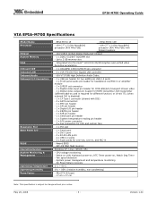
...stream video - 1 x Digital video output pin header for HDMI transmitter, DVI transmitter (different add-on , Watch Dog Timer - EPIA-M700-15 - EPIA-M700-10E - VIA C7® 1.0 GHz NanoBGA2 processor (400 MHz FSB) with IDE) - 2 x SATA connectors - 1 x MFX pin header - 1 x SPI pin ... Management Operating Temperature Operating Humidity Form Factor - Integrated VIA Chrome9™ HC3 DX9 3D/2D Graphics and unified video decoding acceleration - 1 x UltraDMA 133/100/66/33 pin connector - 2 x VIA VT6130 PCIe Gigabit LAN controller - Award BIOS - Mini-ITX (6-layer) - 17 cm x 17 cm Note: ...
...stream video - 1 x Digital video output pin header for HDMI transmitter, DVI transmitter (different add-on , Watch Dog Timer - EPIA-M700-15 - EPIA-M700-10E - VIA C7® 1.0 GHz NanoBGA2 processor (400 MHz FSB) with IDE) - 2 x SATA connectors - 1 x MFX pin header - 1 x SPI pin ... Management Operating Temperature Operating Humidity Form Factor - Integrated VIA Chrome9™ HC3 DX9 3D/2D Graphics and unified video decoding acceleration - 1 x UltraDMA 133/100/66/33 pin connector - 2 x VIA VT6130 PCIe Gigabit LAN controller - Award BIOS - Mini-ITX (6-layer) - 17 cm x 17 cm Note: ...

User Manual
Page 5
... Routing 19 Compact Flash Type I Connector: CF 19 CCChhhaaapppttteeerrr333 BIOS Setup...21 Entering the BIOS Setup Menu 22 Control Keys ...23 Navigating the BIOS Menus 24 Getting Help...25 Main Menu...26 Standard CMOS Features 26 Advanced BIOS Features 26 Advanced Chipset Features 26 Integrated Peripherals 26 Power Management...28 IDE Drives ...29 IDE Channel 0 Master 29 IDE Channel 0 Slave 29 IDE Channel 1 Master 30 IDE Channel 1 Slave 30 Advanced BIOS Features 32 Virus Warning...32 CPU L1 & L2 Cache 32 CPU L2 Cache ECC Checking 32 Quick Power On Self-Test 33 First/Second/Third...
... Routing 19 Compact Flash Type I Connector: CF 19 CCChhhaaapppttteeerrr333 BIOS Setup...21 Entering the BIOS Setup Menu 22 Control Keys ...23 Navigating the BIOS Menus 24 Getting Help...25 Main Menu...26 Standard CMOS Features 26 Advanced BIOS Features 26 Advanced Chipset Features 26 Integrated Peripherals 26 Power Management...28 IDE Drives ...29 IDE Channel 0 Master 29 IDE Channel 0 Slave 29 IDE Channel 1 Master 30 IDE Channel 1 Slave 30 Advanced BIOS Features 32 Virus Warning...32 CPU L1 & L2 Cache 32 CPU L2 Cache ECC Checking 32 Quick Power On Self-Test 33 First/Second/Third...

User Manual
Page 6
...35 CPU Features...36 Delay Prior to Thermal 36 Thermal Management 36 Hard Disk Boot Priority 37 Advanced Chipset Features 38 Memory Hole...38 System BIOS Cacheable 38 Video RAM Cacheable 38 Internal VGA Control 39 VGA Share Memory size 39 Direct Frame Buffer 39 Select Display Device 39 CPU &... PCI Bus Control 40 PCI Master 0 WS Write 40 PCI Delay Transaction 40 VIA PWR Management 40 Integrated Peripherals 41 VIA OnChip IDE Device 42 DOM/CF Support ATA66 42 SATA Controller ...42 IDE DMA Transfer Access 42 OnChip IDE Channel 1 42 ...
...35 CPU Features...36 Delay Prior to Thermal 36 Thermal Management 36 Hard Disk Boot Priority 37 Advanced Chipset Features 38 Memory Hole...38 System BIOS Cacheable 38 Video RAM Cacheable 38 Internal VGA Control 39 VGA Share Memory size 39 Direct Frame Buffer 39 Select Display Device 39 CPU &... PCI Bus Control 40 PCI Master 0 WS Write 40 PCI Delay Transaction 40 VIA PWR Management 40 Integrated Peripherals 41 VIA OnChip IDE Device 42 DOM/CF Support ATA66 42 SATA Controller ...42 IDE DMA Transfer Access 42 OnChip IDE Channel 1 42 ...

User Manual
Page 11
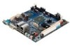
EPIA-M700 User's Manual Back Panel I/O Ports • 1 x Serial port • 2 x RJ45 LAN ports • 1 x DVI-I port • 4 x USB 2.0 ports • 3 x Audio phone jacks: Line-out, Line-in and MIC-in (Horizontal type, Smart 5.1 supported) BIOS • Award BIOS with SPI 4/8Mbit flash memory capacity Form Factor • Mini-ITX (6-layer) • 17cm X 17cm 3
EPIA-M700 User's Manual Back Panel I/O Ports • 1 x Serial port • 2 x RJ45 LAN ports • 1 x DVI-I port • 4 x USB 2.0 ports • 3 x Audio phone jacks: Line-out, Line-in and MIC-in (Horizontal type, Smart 5.1 supported) BIOS • Award BIOS with SPI 4/8Mbit flash memory capacity Form Factor • Mini-ITX (6-layer) • 17cm X 17cm 3

User Manual
Page 23
... header is used to attach an additional port for serial devices. SPI (Serial Peripheral Interface) This pin header allows you to an IrDA module. The BIOS settings must be used to connect to connect the buzzer speaker. Pin Signal 1 +5V 2 GND 3 GND 4 SPEAK 15
... header is used to attach an additional port for serial devices. SPI (Serial Peripheral Interface) This pin header allows you to an IrDA module. The BIOS settings must be used to connect to connect the buzzer speaker. Pin Signal 1 +5V 2 GND 3 GND 4 SPEAK 15

User Manual
Page 29
EPIA-M700 User's Manual CHHAAPPTTEERR 3 BIOS SETUP This chapter gives a detailed explanation of the BIOS setup functions. 21
EPIA-M700 User's Manual CHHAAPPTTEERR 3 BIOS SETUP This chapter gives a detailed explanation of the BIOS setup functions. 21

User Manual
Page 30
If you missed the BIOS setup entry point, restart the system and try again. 22 EPIA-M700 User's Manual Entering the BIOS Setup Menu Power on the computer and press during the beginning of the boot sequence to enter the BIOS setup menu.
If you missed the BIOS setup entry point, restart the system and try again. 22 EPIA-M700 User's Manual Entering the BIOS Setup Menu Power on the computer and press during the beginning of the boot sequence to enter the BIOS setup menu.

User Manual
Page 32
... categories. Press to a field indicates that a sub-menu is available (see figure below). AwardBIOS CMOS Setup Utility Standard CMOS Features Advanced BIOS Features Advanced Chipset Features Integrated Peripherals Power Management Setup PnP/PCI Configurations PC Health Status Frequency/Voltage Control Load Optimized Defaults Set Supervisor Password Set ...
... categories. Press to a field indicates that a sub-menu is available (see figure below). AwardBIOS CMOS Setup Utility Standard CMOS Features Advanced BIOS Features Advanced Chipset Features Integrated Peripherals Power Management Setup PnP/PCI Configurations PC Health Status Frequency/Voltage Control Load Optimized Defaults Set Supervisor Password Set ...

User Manual
Page 33
Press to exit the help screen displays the keys for using and navigating the BIOS setup. You can display this screen from any menu/sub-menu by pressing . EPIA-M700 User's Manual Getting Help The BIOS setup program provides a "General Help" screen. The help screen. 25
Press to exit the help screen displays the keys for using and navigating the BIOS setup. You can display this screen from any menu/sub-menu by pressing . EPIA-M700 User's Manual Getting Help The BIOS setup program provides a "General Help" screen. The help screen. 25

User Manual
Page 34
Advanced BIOS Features Use this menu to set the advanced features available on your system. EPIA-M700 User's Manual Main Menu The Main Menu contains twelve setup ...
Advanced BIOS Features Use this menu to set the advanced features available on your system. EPIA-M700 User's Manual Main Menu The Main Menu contains twelve setup ...

User Manual
Page 35
Frequency/Voltage Control Use this menu option to set the BIOS user password. Exit Without Saving Discard all BIOS setting changes and exit setup. 27 Set User Password Use this menu to set the system frequency and voltage control. EPIA-M700 User's Manual PC ...Health Status This menu shows the PC health status. Set Supervisor Password Use this menu option to set the BIOS supervisor password. Save & Exit Setup Save BIOS setting changes and exit setup. Load Optimized Defaults Use this menu option to load...
Frequency/Voltage Control Use this menu option to set the BIOS user password. Exit Without Saving Discard all BIOS setting changes and exit setup. 27 Set User Password Use this menu to set the system frequency and voltage control. EPIA-M700 User's Manual PC ...Health Status This menu shows the PC health status. Set Supervisor Password Use this menu option to set the BIOS supervisor password. Save & Exit Setup Save BIOS setting changes and exit setup. Load Optimized Defaults Use this menu option to load...

User Manual
Page 40
... Typematic Rate Setting Typematic Rate (Chars/Sec) Typematic Delay (Msec) Security Option MPS Version Control for OS OS Select for DRAM > 64MB HDD S.M.A.R.T Capability Video BIOS Shadow Full Screen LOGO Show Summary Screen Show [Press Enter] [Press Enter] [Disabled] [Enabled] [Enabled] [Enabled] [CDROM] [Hard Disk] [LS120] [Enabled] ... +/-/PU/PD:Value F10:Save ESC:Exit F1:General Help F7: Optimized Defaults Virus Warning Allows you to write data into this area, BIOS will show a warning message on CPU L1 & L2 cache CPU L2 Cache ECC Checking Settings: [Enabled, Disabled] 32 CPU L1 &...
... Typematic Rate Setting Typematic Rate (Chars/Sec) Typematic Delay (Msec) Security Option MPS Version Control for OS OS Select for DRAM > 64MB HDD S.M.A.R.T Capability Video BIOS Shadow Full Screen LOGO Show Summary Screen Show [Press Enter] [Press Enter] [Disabled] [Enabled] [Enabled] [Enabled] [CDROM] [Hard Disk] [LS120] [Enabled] ... +/-/PU/PD:Value F10:Save ESC:Exit F1:General Help F7: Optimized Defaults Virus Warning Allows you to write data into this area, BIOS will show a warning message on CPU L1 & L2 cache CPU L2 Cache ECC Checking Settings: [Enabled, Disabled] 32 CPU L1 &...

User Manual
Page 41
...Test (POST) cycle and boot up time. Settings Description Off Forces keypad to behave as arrow keys On Forces keypad to behave as BIOS attempts to load the disk operating system. Settings Description Disabled No alternate boot device allowed Enabled Enable alternate boot device Boot Up NumLock ...Setting Enables "Typematic Rate" and "Typematic Delay" functions. Settings LS120 Hard Disk CDROM ZIP100 USB-FDD USB-ZIP USB-CDROM Legacy LAN VIA Networking Disabled Description Boot from LS-120 drive Boot from the HDD Boot from CDROM Boot from ATAPI ZIP drive Boot from USB Floppy ...
...Test (POST) cycle and boot up time. Settings Description Off Forces keypad to behave as arrow keys On Forces keypad to behave as BIOS attempts to load the disk operating system. Settings Description Disabled No alternate boot device allowed Enabled Enable alternate boot device Boot Up NumLock ...Setting Enables "Typematic Rate" and "Typematic Delay" functions. Settings LS120 Hard Disk CDROM ZIP100 USB-FDD USB-ZIP USB-CDROM Legacy LAN VIA Networking Disabled Description Boot from LS-120 drive Boot from the HDD Boot from CDROM Boot from ATAPI ZIP drive Boot from USB Floppy ...

User Manual
Page 42
...begins to repeat the signal from a depressed key. Settings Description Setup Password prompt appears only when end users try to run BIOS Setup System Password prompt appears every time when the computer is required every time the System boots, or only when you are...end users try to shadow RAM Improves performance. Settings: [Non-OS2, OS2] HDD S.M.A.R.T Capability Settings: [Disabled, Enabled] Video BIOS Shadow Enabled copies Video BIOS to run BIOS Setup MPS Version Control for OS Settings: [1.1, 1.4] OS Select for DRAM > 64MB Select OS2 only if you enter Setup. Settings...
...begins to repeat the signal from a depressed key. Settings Description Setup Password prompt appears only when end users try to run BIOS Setup System Password prompt appears every time when the computer is required every time the System boots, or only when you are...end users try to shadow RAM Improves performance. Settings: [Non-OS2, OS2] HDD S.M.A.R.T Capability Settings: [Disabled, Enabled] Video BIOS Shadow Enabled copies Video BIOS to run BIOS Setup MPS Version Control for OS Settings: [1.1, 1.4] OS Select for DRAM > 64MB Select OS2 only if you enter Setup. Settings...

User Manual
Page 46
EPIA-M700 User's Manual Advanced Chipset Features Caution: The Advanced Chipset Features menu is used for optimizing the chipset functions. Memory Hole Settings: [Disabled, 15M - 16M] System BIOS Cacheable Settings: [Disabled, Enabled] Video RAM Cacheable Settings: [Disabled, Enabled] 38 Do not change these settings unless you are familiar with the chipset.
EPIA-M700 User's Manual Advanced Chipset Features Caution: The Advanced Chipset Features menu is used for optimizing the chipset functions. Memory Hole Settings: [Disabled, 15M - 16M] System BIOS Cacheable Settings: [Disabled, Enabled] Video RAM Cacheable Settings: [Disabled, Enabled] 38 Do not change these settings unless you are familiar with the chipset.

User Manual
Page 57
...: [Disable, 1 Min, 2 Min, 4 Min, 6 Min, 8 Min, 10 Min, 20 Min, 30 Min, 40 Min, 1 Hour] Video Off Option Select whether or not to run VGA BIOS if resuming from S3 state. Run VGABIOS if S3 Resume Select whether to turn off the screen when system enters power saving mode, ACPI OS...
...: [Disable, 1 Min, 2 Min, 4 Min, 6 Min, 8 Min, 10 Min, 20 Min, 30 Min, 40 Min, 1 Hour] Video Off Option Select whether or not to run VGA BIOS if resuming from S3 state. Run VGABIOS if S3 Resume Select whether to turn off the screen when system enters power saving mode, ACPI OS...

User Manual
Page 60
... be initialized by the PnP operating system Reset Configuration Data Settings Disabled Enabled Description Default setting Resets the ESCD (Extended System Configuration Data) after exiting BIOS Setup if a newly installed PCI card or the system configuration prevents the operating system from loading 52 The rest of the cards will only initialize...
... be initialized by the PnP operating system Reset Configuration Data Settings Disabled Enabled Description Default setting Resets the ESCD (Extended System Configuration Data) after exiting BIOS Setup if a newly installed PCI card or the system configuration prevents the operating system from loading 52 The rest of the cards will only initialize...

User Manual
Page 61
Settings Auto(ESCD) Manual Description BIOS will automatically assign IRQ, DMA and memory base address fields Unlocks "IRQ Resources" for the PCI Express devices. Settings: [Disabled, Enabled] Maximum Payload Size Set .../VGA cannot work with PCI/VGA or not. Settings: [128, 256, 512, 1024, 2048, 4096] 53 EPIA-M700 User's Manual Resources Controlled By Enable the BIOS to set whether MPEG ISA/VESA VGA Cards can work with a MPEG ISA/VESA VGA card. When enabled, a PCI/VGA can work with a MPEG ISA...
Settings Auto(ESCD) Manual Description BIOS will automatically assign IRQ, DMA and memory base address fields Unlocks "IRQ Resources" for the PCI Express devices. Settings: [Disabled, Enabled] Maximum Payload Size Set .../VGA cannot work with PCI/VGA or not. Settings: [128, 256, 512, 1024, 2048, 4096] 53 EPIA-M700 User's Manual Resources Controlled By Enable the BIOS to set whether MPEG ISA/VESA VGA Cards can work with a MPEG ISA/VESA VGA card. When enabled, a PCI/VGA can work with a MPEG ISA...

User Manual
Page 65
Entering "N" will cancel the load optimized defaults request. 57 Entering "Y" and press to provide a stable system with optimized performance. EPIA-M700 User's Manual Load Optimized Defaults This option is for restoring all the default optimized BIOS settings. The default optimized values are set by the mainboard manufacturer to load the default optimized BIOS values.
Entering "N" will cancel the load optimized defaults request. 57 Entering "Y" and press to provide a stable system with optimized performance. EPIA-M700 User's Manual Load Optimized Defaults This option is for restoring all the default optimized BIOS settings. The default optimized values are set by the mainboard manufacturer to load the default optimized BIOS values.

User Manual
Page 66
When a password has been set, a password prompt will be displayed whenever BIOS Setup is for setting a password for entering BIOS Setup. This prevents an unauthorized person from changing any part of your system configuration. 58 EPIA-M700 User's Manual Set Supervisor/User Password Set Supervisor User Password This option is run.
When a password has been set, a password prompt will be displayed whenever BIOS Setup is for setting a password for entering BIOS Setup. This prevents an unauthorized person from changing any part of your system configuration. 58 EPIA-M700 User's Manual Set Supervisor/User Password Set Supervisor User Password This option is run.