
User Manual
Page 3
..., pursuant to part 15 of this equipment in a residential area is operated in accordance with the instruction manual, may cause harmful interference to radio communications. power cord, if any, must be required to correct the interference at his personal expense. Operation of the FCC rules. FCC-B Radio Frequency Interference Statement This...
..., pursuant to part 15 of this equipment in a residential area is operated in accordance with the instruction manual, may cause harmful interference to radio communications. power cord, if any, must be required to correct the interference at his personal expense. Operation of the FCC rules. FCC-B Radio Frequency Interference Statement This...

User Manual
Page 4
...3. Keep this User's Manual for air convection hence protects the equipment from humidity. 4. Keep this equipment away from overheating. Always unplug the power cord before connecting the equipment to User's Manual. • The equipment has dropped and damaged • If the equipment has obvious sign of... the following situations arises, get it work according to the power inlet. 7. Never pour any of breakage 12. DO NOT COVER THE OPENINGS. 6. Liquid can cause damage or electrical shock. 11. DO ...
...3. Keep this User's Manual for air convection hence protects the equipment from humidity. 4. Keep this equipment away from overheating. Always unplug the power cord before connecting the equipment to User's Manual. • The equipment has dropped and damaged • If the equipment has obvious sign of... the following situations arises, get it work according to the power inlet. 7. Never pour any of breakage 12. DO NOT COVER THE OPENINGS. 6. Liquid can cause damage or electrical shock. 11. DO ...
User Manual
Page 6
... SPECIFICATIONS 2 MAINBOARD LAYOUT 4 BACK PANEL LAYOUT 4 INSTALLATION 5 CPU 6 CPU Fan: CPU_FAN 6 MEMORY MODULE INSTALLATION 7 Memory Slot: DDR2_SODIMM 7 Available DDR2 SDRAM Configurations 7 CONNECTING THE POWER SUPPLY 8 Pico-ITX 12-Pin Power Connector 8 BACK PANEL PORTS 9 VGA Port 9 RJ45 LAN Port 9 CONNECTORS 10 IDE Connector: IDE 10 Serial ATA Connectors: SATA 11 USB Pin Connector: USB...
... SPECIFICATIONS 2 MAINBOARD LAYOUT 4 BACK PANEL LAYOUT 4 INSTALLATION 5 CPU 6 CPU Fan: CPU_FAN 6 MEMORY MODULE INSTALLATION 7 Memory Slot: DDR2_SODIMM 7 Available DDR2 SDRAM Configurations 7 CONNECTING THE POWER SUPPLY 8 Pico-ITX 12-Pin Power Connector 8 BACK PANEL PORTS 9 VGA Port 9 RJ45 LAN Port 9 CONNECTORS 10 IDE Connector: IDE 10 Serial ATA Connectors: SATA 11 USB Pin Connector: USB...

User Manual
Page 7
... BIOS MENUS 22 GETTING HELP 23 MAIN MENU 24 Standard CMOS Features 24 Advanced BIOS Features 24 Advanced Chipset Features 24 Integrated Peripherals 24 Power Management Setup 24 PnP/PCI Configurations 24 Frequency/Voltage Control 24 Load Fail-Safe Defaults 25 Load Optimized Defaults 25 Set Supervisor Password 25...STANDARD CMOS FEATURES 26 Date 26 Time 26 Halt On 26 Video 26 IDE DRIVES 27 ADVANCED BIOS FEATURES 28 Virus Warning 28 Quick Power On Self-Test 28 First/Second/Third Boot Device 29 Boot Other Device 29 Boot Up NumLock Status 29 Typematic Rate Setting 29 Security...
... BIOS MENUS 22 GETTING HELP 23 MAIN MENU 24 Standard CMOS Features 24 Advanced BIOS Features 24 Advanced Chipset Features 24 Integrated Peripherals 24 Power Management Setup 24 PnP/PCI Configurations 24 Frequency/Voltage Control 24 Load Fail-Safe Defaults 25 Load Optimized Defaults 25 Set Supervisor Password 25...STANDARD CMOS FEATURES 26 Date 26 Time 26 Halt On 26 Video 26 IDE DRIVES 27 ADVANCED BIOS FEATURES 28 Virus Warning 28 Quick Power On Self-Test 28 First/Second/Third Boot Device 29 Boot Other Device 29 Boot Up NumLock Status 29 Typematic Rate Setting 29 Security...

User Manual
Page 9
... 41 USB 2.0 Controller 41 USB Operation Mode 41 USB Keyboard Function 42 USB Storage Function 42 No Device 42 POWER MANAGEMENT SETUP 43 ACPI Suspend Type 43 Power Management Option 43 HDD Power Down 43 Suspend Mode 43 Video Off Option 44 Video Off Method 44 MODEM Use IRQ 44 Soft-Off by... Auto restart 44 WAKEUP EVENT DETECT 45 PS2KB Wakeup Select 45 PS2KB Wakeup Key Select 45 PS2MS Wakeup Key Select 45 PS2 Keyboard Power On 46 PS2 Mouse Power On 46 PowerOn by PCI Card 46 Modem Ring Resume 46 RTC Alarm Resume 46 Date (of Month 46 Resume Time (hh:mm...
... 41 USB 2.0 Controller 41 USB Operation Mode 41 USB Keyboard Function 42 USB Storage Function 42 No Device 42 POWER MANAGEMENT SETUP 43 ACPI Suspend Type 43 Power Management Option 43 HDD Power Down 43 Suspend Mode 43 Video Off Option 44 Video Off Method 44 MODEM Use IRQ 44 Soft-Off by... Auto restart 44 WAKEUP EVENT DETECT 45 PS2KB Wakeup Select 45 PS2KB Wakeup Key Select 45 PS2MS Wakeup Key Select 45 PS2 Keyboard Power On 46 PS2 Mouse Power On 46 PowerOn by PCI Card 46 Modem Ring Resume 46 RTC Alarm Resume 46 Date (of Month 46 Resume Time (hh:mm...
User Manual
Page 14
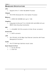
Chapter 1 MAINBOARD SPECIFICATIONS CPU • Supports VIA C7 1.0GHz NanoBGA2 Processor Chipset • VIA VX700 Advanced All-in-One System Processor Memory • 1 x DDR2 533 SODIMM slot (up to 1 GB) Graphics • Integrated UniChrome™... Acceleration IDE • 1 x UltraDMA 133/100 connector (2.0mm 40-pin connector) Serial ATA • 1 x SATA connector LAN • VIA VT6106S 10/100 Mbps Fast Ethernet Controller with Power Management Functions Audio • VIA VT1708A High Definition Audio Codec Back Panel I/O Port • 1 x RJ-45 LAN Port • 1 x VGA Port 2
Chapter 1 MAINBOARD SPECIFICATIONS CPU • Supports VIA C7 1.0GHz NanoBGA2 Processor Chipset • VIA VX700 Advanced All-in-One System Processor Memory • 1 x DDR2 533 SODIMM slot (up to 1 GB) Graphics • Integrated UniChrome™... Acceleration IDE • 1 x UltraDMA 133/100 connector (2.0mm 40-pin connector) Serial ATA • 1 x SATA connector LAN • VIA VT6106S 10/100 Mbps Fast Ethernet Controller with Power Management Functions Audio • VIA VT1708A High Definition Audio Codec Back Panel I/O Port • 1 x RJ-45 LAN Port • 1 x VGA Port 2

User Manual
Page 15
...; 1 Multimedia connector to support External TV-Out Interface, Video Capture Port Interface and Low Pin Count Interface. (One VT1625M add-on card is required.) • 1 x Pico-ITX power connector BIOS • Award BIOS with LPC 4/8Mbit flash memory capacity Form Factor •...
...; 1 Multimedia connector to support External TV-Out Interface, Video Capture Port Interface and Low Pin Count Interface. (One VT1625M add-on card is required.) • 1 x Pico-ITX power connector BIOS • Award BIOS with LPC 4/8Mbit flash memory capacity Form Factor •...

User Manual
Page 20
Then push down the plug firmly into the connector. Chapter 2 CONNECTING THE POWER SUPPLY The VIA EPIA-PX Pico-ITX mainboard supports a Pico-ITX power supply for the power system. Pico-ITX 12-Pin Power Connector To connect the power supply, make sure that all components are aligned. Pin Signal 1 +3.3V 2 +5V_SB 3 +12V 4 +5V 5 +5V 6 PWRGD 7 +3.3V 8 +3.3V 9 GND 10 PWRON 11 GND 12...
Then push down the plug firmly into the connector. Chapter 2 CONNECTING THE POWER SUPPLY The VIA EPIA-PX Pico-ITX mainboard supports a Pico-ITX power supply for the power system. Pico-ITX 12-Pin Power Connector To connect the power supply, make sure that all components are aligned. Pin Signal 1 +3.3V 2 +5V_SB 3 +12V 4 +5V 5 +5V 6 PWRGD 7 +3.3V 8 +3.3V 9 GND 10 PWRON 11 GND 12...
User Manual
Page 24
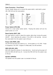
...light when the system is connected to this pin. Speaker (SPEAK) The speaker from the system case to this button will turn the system power on . Power On Suspend) or S3 (STR - Chapter 2 Case Connector: Front Panel This pin header allows you to reboot the system rather than turning the...#EXTSMI 13 SPEAK 15 NC Pin Signal 2 +5V 4 HDD_LED 6 PW_BN 8 GND 10 RST_SW 12 GND 14 +5V 16 #SLEEP_LED 1 2 15 16 Power Switch (PW_BN) Connect to this pin. Power LED (PWR_LED) The LED will blink. Connect the HDD LED from the system case is on or off when the HDD LED...
...light when the system is connected to this pin. Speaker (SPEAK) The speaker from the system case to this button will turn the system power on . Power On Suspend) or S3 (STR - Chapter 2 Case Connector: Front Panel This pin header allows you to reboot the system rather than turning the...#EXTSMI 13 SPEAK 15 NC Pin Signal 2 +5V 4 HDD_LED 6 PW_BN 8 GND 10 RST_SW 12 GND 14 +5V 16 #SLEEP_LED 1 2 15 16 Power Switch (PW_BN) Connect to this pin. Power LED (PWR_LED) The LED will blink. Connect the HDD LED from the system case is on or off when the HDD LED...

User Manual
Page 29
... on will explain how to pins 1 and 2 afterwards. Clear CMOS: CMOS Reset The onboard CMOS RAM stores system configuration data and has an onboard battery power supply. Removing the cap will damage the mainboard. 17 Avoid clearing the CMOS while the system is off. Return the jumper to change the settings...
... on will explain how to pins 1 and 2 afterwards. Clear CMOS: CMOS Reset The onboard CMOS RAM stores system configuration data and has an onboard battery power supply. Removing the cap will damage the mainboard. 17 Avoid clearing the CMOS while the system is off. Return the jumper to change the settings...

User Manual
Page 32
If you missed the BIOS setup entry point, you may restart the system and try again. 20 Chapter 3 ENTERING SETUP Power on the computer and press during the beginning of the boot sequence to enter the BIOS setup menu.
If you missed the BIOS setup entry point, you may restart the system and try again. 20 Chapter 3 ENTERING SETUP Power on the computer and press during the beginning of the boot sequence to enter the BIOS setup menu.

User Manual
Page 36
PnP/PCI Configurations Use this menu to set onboard power management functions. Power Management Setup Use this menu to set the PnP and PCI configurations. Advanced Chipset Features Use this menu to set the ...menu to set chipset specific features and optimize system performance. AwardBIOS CMOS Setup Utility Standard CMOS Features Advanced BIOS Features Advanced Chipset Features Integrated Peripherals Power Management Setup PnP / PCI Configurations Frequency / Voltage Control Load Fail-Safe Defaults Load Optimized Defaults Set Supervisor Password Set User Password Save &...
PnP/PCI Configurations Use this menu to set onboard power management functions. Power Management Setup Use this menu to set the PnP and PCI configurations. Advanced Chipset Features Use this menu to set the ...menu to set chipset specific features and optimize system performance. AwardBIOS CMOS Setup Utility Standard CMOS Features Advanced BIOS Features Advanced Chipset Features Integrated Peripherals Power Management Setup PnP / PCI Configurations Frequency / Voltage Control Load Fail-Safe Defaults Load Optimized Defaults Set Supervisor Password Set User Password Save &...

User Manual
Page 40
Chapter 3 ADVANCED BIOS FEATURES Phoenix - AwardBIOS CMOS Setup Utility Advanced BIOS Features CPU Feature Hard Disk Boot Priority Virus Warning Quick Power On Self Test First Boot Device Second Boot Device Third Boot Device Boot Other Device Boot Up NumLock Status Typematic Rate Setting Typematic ... Virus Warning Setting Enabled Disabled Description Turns on hard disk boot sector virus protection Turns off hard disk boot sector virus protection Quick Power On Self-Test Shortens Power On Self-Test (POST) cycle to enable shorter boot up time. Setting Enabled Disabled Description Shorten...
Chapter 3 ADVANCED BIOS FEATURES Phoenix - AwardBIOS CMOS Setup Utility Advanced BIOS Features CPU Feature Hard Disk Boot Priority Virus Warning Quick Power On Self Test First Boot Device Second Boot Device Third Boot Device Boot Other Device Boot Up NumLock Status Typematic Rate Setting Typematic ... Virus Warning Setting Enabled Disabled Description Turns on hard disk boot sector virus protection Turns off hard disk boot sector virus protection Quick Power On Self-Test Shortens Power On Self-Test (POST) cycle to enable shorter boot up time. Setting Enabled Disabled Description Shorten...

User Manual
Page 41
... Setting Enabled Disabled Description Enable alternate boot device No alternate boot device allowed Boot Up NumLock Status Set the NumLock status when the system is powered on. BIOS Setup First/Second/Third Boot Device Set the boot device sequence as arrow keys Typematic Rate Setting Enables "Typematic Rate" and "Typematic Delay...
... Setting Enabled Disabled Description Enable alternate boot device No alternate boot device allowed Boot Up NumLock Status Set the NumLock status when the system is powered on. BIOS Setup First/Second/Third Boot Device Set the boot device sequence as arrow keys Typematic Rate Setting Enables "Typematic Rate" and "Typematic Delay...
User Manual
Page 42
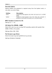
... Settings: [Non-OS2, OS2] Full Screen Logo Show Show full screen logo during BIOS boot up process. Chapter 3 Security Option Selects whether the password is powered on and when end users try to run BIOS Setup MPS Variation Control for OS Settings: [1.1, 1.4] OS Select For DRAM > 64MB Select OS2 only if...
... Settings: [Non-OS2, OS2] Full Screen Logo Show Show full screen logo during BIOS boot up process. Chapter 3 Security Option Selects whether the password is powered on and when end users try to run BIOS Setup MPS Variation Control for OS Settings: [1.1, 1.4] OS Select For DRAM > 64MB Select OS2 only if...

User Manual
Page 55
... (POS) is lost and hardware maintains all system contexts. In this state, no system context (CPU or chipset) is a low power state. In this state, power is supplied only to select S1 or S3. Depends on the OS to essential components such as main memory and wakeup-capable devices.... The system context is saved to main memory, and context is a power-down the hard disk. Settings: [Disabled, 1~15(minutes)] Suspend Mode Settings:[Disabled, 1 Min, 2 Min, 4 Min, 6 Min, 8 Min, 10 Min, 20 Min, 30 Min...
... (POS) is lost and hardware maintains all system contexts. In this state, no system context (CPU or chipset) is a low power state. In this state, power is supplied only to select S1 or S3. Depends on the OS to essential components such as main memory and wakeup-capable devices.... The system context is saved to main memory, and context is a power-down the hard disk. Settings: [Disabled, 1~15(minutes)] Suspend Mode Settings:[Disabled, 1 Min, 2 Min, 4 Min, 6 Min, 8 Min, 10 Min, 20 Min, 30 Min...

User Manual
Page 56
...back Former-Sts 44 Chapter 3 Video Off Option Select whether or not to turn off the screen when system enters power saving mode, ACPI OS such as a normal power-on/-off button Run VGABIOS if S3 Resume Select whether to run VGA BIOS if resuming from S3 state. Setting... Always On Suspend -> Off Description Screen is always on even when system enters power saving mode Screen is turned off when system enters power saving mode Video Off Method Settings:[Blank Screen, V/H SYNC+Blank, DPMS Support] MODEM Use IRQ Settings: [NA, 3, 4, 5, 7, 9,...
...back Former-Sts 44 Chapter 3 Video Off Option Select whether or not to turn off the screen when system enters power saving mode, ACPI OS such as a normal power-on/-off button Run VGABIOS if S3 Resume Select whether to run VGA BIOS if resuming from S3 state. Setting... Always On Suspend -> Off Description Screen is always on even when system enters power saving mode Screen is turned off when system enters power saving mode Video Off Method Settings:[Blank Screen, V/H SYNC+Blank, DPMS Support] MODEM Use IRQ Settings: [NA, 3, 4, 5, 7, 9,...

User Manual
Page 57
..., press Enter to an active state. WAKEUP EVENT DETECT BIOS Setup PS2KB Wakeup Select PS2KB Wakeup Key Select PS2MS Wakeup Key Select PS2 Keyboard Power On PS2 Mouse Power On PowerOn by PCI Card Modem Ring Resume RTC Alarm Resume Date (of characters is eight. Settings: [Ctrl+F1, Ctrl+F2, Ctrl+F3..., Ctrl+F5, Ctrl+F6, Ctrl+F7, Ctrl+F8, Ctrl+F9, Ctrl+F10, Ctrl+F11, Ctrl+F12, Power, Wake, Any Key] PS2MS Wakeup Key Select Enables any mouse activity to restore the system from the power saving mode to change password. Settings: [Any Botton, Left Botton, Right Botton] 45 The maximum number of...
..., press Enter to an active state. WAKEUP EVENT DETECT BIOS Setup PS2KB Wakeup Select PS2KB Wakeup Key Select PS2MS Wakeup Key Select PS2 Keyboard Power On PS2 Mouse Power On PowerOn by PCI Card Modem Ring Resume RTC Alarm Resume Date (of characters is eight. Settings: [Ctrl+F1, Ctrl+F2, Ctrl+F3..., Ctrl+F5, Ctrl+F6, Ctrl+F7, Ctrl+F8, Ctrl+F9, Ctrl+F10, Ctrl+F11, Ctrl+F12, Power, Wake, Any Key] PS2MS Wakeup Key Select Enables any mouse activity to restore the system from the power saving mode to change password. Settings: [Any Botton, Left Botton, Right Botton] 45 The maximum number of...

User Manual
Page 58
... the time for "RTC Alarm Resume". Settings: [Disabled, Enabled] Date (of Month) The field specifies the date for "RTC Alarm Resume". 46 Chapter 3 PS2 Keyboard Power On Settings: [Disabled, Enabled] PS2 Mouse Power On Settings: [Disabled, Enabled] PowerOn by PCI Card Enables activity detected from any PCI card to automatically...
... the time for "RTC Alarm Resume". Settings: [Disabled, Enabled] Date (of Month) The field specifies the date for "RTC Alarm Resume". 46 Chapter 3 PS2 Keyboard Power On Settings: [Disabled, Enabled] PS2 Mouse Power On Settings: [Disabled, Enabled] PowerOn by PCI Card Enables activity detected from any PCI card to automatically...

User Manual
Page 64
... the mainboard manufacturer to provide a stable system with basic performance. AwardBIOS CMOS Setup Utility Standard CMOS Features Advanced BIOS Features Advanced Chipset Features Integrated Peripherals Power Management Setup PnP / PCI Configurations Frequency / Voltage Control Load Fail-Safe Defaults Load Optimized Defaults Set Supervisor Password Set User Password Save & Exit Setup Load...
... the mainboard manufacturer to provide a stable system with basic performance. AwardBIOS CMOS Setup Utility Standard CMOS Features Advanced BIOS Features Advanced Chipset Features Integrated Peripherals Power Management Setup PnP / PCI Configurations Frequency / Voltage Control Load Fail-Safe Defaults Load Optimized Defaults Set Supervisor Password Set User Password Save & Exit Setup Load...