User Manual
Page 6
...2: Installation 2-1 CPU Installation 2-2 Memory Module Installation 2-4 Connecting the Power Supply 2-6 Back Panel Ports 2-7 Connectors 2-12 Jumpers 2-19 Slots 2-20 Chapter 3: BIOS Setup 3-1 Entering Setup 3-2 Control Keys 3-2 Gettings Help 3-3 The Main Menu 3-4 Standard CMOS Features 3-6 Advanced BIOS Features 3-8 Advanced Chipset Features 3-11 Integrated Peripherals 3-13 Power Management Setup 3-17 PNP / PCI Configurations 3-22 PC Health Status 3-25 Frequency / Voltage Control 3-26 Load Fail-Safe Defaults 3-28 Load Optimized Defaults 3-29 Set Supervisor / User Password...
...2: Installation 2-1 CPU Installation 2-2 Memory Module Installation 2-4 Connecting the Power Supply 2-6 Back Panel Ports 2-7 Connectors 2-12 Jumpers 2-19 Slots 2-20 Chapter 3: BIOS Setup 3-1 Entering Setup 3-2 Control Keys 3-2 Gettings Help 3-3 The Main Menu 3-4 Standard CMOS Features 3-6 Advanced BIOS Features 3-8 Advanced Chipset Features 3-11 Integrated Peripherals 3-13 Power Management Setup 3-17 PNP / PCI Configurations 3-22 PC Health Status 3-25 Frequency / Voltage Control 3-26 Load Fail-Safe Defaults 3-28 Load Optimized Defaults 3-29 Set Supervisor / User Password...
User Manual
Page 7
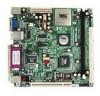
... VIA Processor, boasting ultra low power consumption and cool, quiet operation. This chapter includes the following sections: Mainboard Specifications 1-2 Mainboard Layout 1-4 Back Panel Ports 1-5 Slots 1-5 Connectors / Jumpers 1-6 1-1 The mainboard enables the creation of an exciting new generation of small, ergonomic, innovative and affordable embedded systems. Through high level of integration, miniITX only occupy 66% of the size of the company's open industry-wide total connectivity initiative. as part...
... VIA Processor, boasting ultra low power consumption and cool, quiet operation. This chapter includes the following sections: Mainboard Specifications 1-2 Mainboard Layout 1-4 Back Panel Ports 1-5 Slots 1-5 Connectors / Jumpers 1-6 1-1 The mainboard enables the creation of an exciting new generation of small, ergonomic, innovative and affordable embedded systems. Through high level of integration, miniITX only occupy 66% of the size of the company's open industry-wide total connectivity initiative. as part...

User Manual
Page 12
Chapter 1 Onboard Connectors and Jumpers Connecter/Jumper ATXPWR CD_IN CIR CLEAR_CMOS COM2 F_AUDIO F_PANEL Fans FIR SMBUS IDE 1-2 USB 3/4 WOL Description ATX power cable connector Onboard CD audio cable connector Consumer IR connector Jumper to reset CMOS settings to default Second serial port connector Connectors for optional front audio panel Case connectors CPU, System, Fan3 Fast Infrared Radiation connector SM Bus pin connector IDE hard disk drive connectors Universal Serial Bus connectors 3 - 4 Wake On LAN connector Page 2-6 2-16 2-13 2-18 2-15 2-17 2-12 2-2 2-13 2-16 2-11 2-14 2-14 ...
Chapter 1 Onboard Connectors and Jumpers Connecter/Jumper ATXPWR CD_IN CIR CLEAR_CMOS COM2 F_AUDIO F_PANEL Fans FIR SMBUS IDE 1-2 USB 3/4 WOL Description ATX power cable connector Onboard CD audio cable connector Consumer IR connector Jumper to reset CMOS settings to default Second serial port connector Connectors for optional front audio panel Case connectors CPU, System, Fan3 Fast Infrared Radiation connector SM Bus pin connector IDE hard disk drive connectors Universal Serial Bus connectors 3 - 4 Wake On LAN connector Page 2-6 2-16 2-13 2-18 2-15 2-17 2-12 2-2 2-13 2-16 2-11 2-14 2-14 ...

User Manual
Page 16
The modules will only fit if placed in place (see picture below). 2-4 With both hands, press the DDR SDRAM module down into the DIMM slot so that the white retaining latches rotate up and secure the module in the correct position. 3. Align the DDR SDRAM module with the corresponding notches on the DIMM slot. Push the white retaining latches at either end of the DIMM slot outwards. 2. DDR SDRAM Module Installation Procedures 1. Chapter 2 Memory Module Installation The VIA EPIA-ML Mini-ITX Mainboard provides one 184-pin DIMM slot for DDR266 SDRAM memory modules.
The modules will only fit if placed in place (see picture below). 2-4 With both hands, press the DDR SDRAM module down into the DIMM slot so that the white retaining latches rotate up and secure the module in the correct position. 3. Align the DDR SDRAM module with the corresponding notches on the DIMM slot. Push the white retaining latches at either end of the DIMM slot outwards. 2. DDR SDRAM Module Installation Procedures 1. Chapter 2 Memory Module Installation The VIA EPIA-ML Mini-ITX Mainboard provides one 184-pin DIMM slot for DDR266 SDRAM memory modules.
User Manual
Page 23
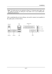
After completing the previous settings, you need to connect your desktop after installing the audio driver. Installation Note: The Audio ports can enable the function by clicking the "Vinyl Audio" icon on your speakers to the audio jacks as shown below. You can be switched to Smart 5.1 6-channel audio output. PS2_MS RJ45 PS2_KB VGA Out USB Parallel (LPT1) COM1 Line-In Line-Out Microphone 2-11
After completing the previous settings, you need to connect your desktop after installing the audio driver. Installation Note: The Audio ports can enable the function by clicking the "Vinyl Audio" icon on your speakers to the audio jacks as shown below. You can be switched to Smart 5.1 6-channel audio output. PS2_MS RJ45 PS2_KB VGA Out USB Parallel (LPT1) COM1 Line-In Line-Out Microphone 2-11

User Manual
Page 27
... to connect a network card with the Wake-On LAN function. Installation USB pin-header: USB3/4 The mainboard provides 1 front USB pin-header connector, allowing up the system when a signal is received through the network card. Pin Signal 1 VCC 3 USB2 5 USB2 + 7 GND 9 NC Pin Signal 2 VCC 4 USB 3 6 USB 3 + 8 GND 10 GND 2 10 1 9 USB 3/4 Wake-on LAN: WOL This connector allows you to 2 additional USB ports. Please note that the function of ACPI WOL may be disabled when users unplug the power cord or turn...
... to connect a network card with the Wake-On LAN function. Installation USB pin-header: USB3/4 The mainboard provides 1 front USB pin-header connector, allowing up the system when a signal is received through the network card. Pin Signal 1 VCC 3 USB2 5 USB2 + 7 GND 9 NC Pin Signal 2 VCC 4 USB 3 6 USB 3 + 8 GND 10 GND 2 10 1 9 USB 3/4 Wake-on LAN: WOL This connector allows you to 2 additional USB ports. Please note that the function of ACPI WOL may be disabled when users unplug the power cord or turn...

User Manual
Page 32
... 4 INT A# 2-20 When adding or removing expansion cards, make any necessary hardware or software settings for the expansion card to the PCI bus INT A# ~ INT D# pins as jumpers, switches or BIOS configuration. Chapter 2 Slots Peripheral Component Interconnect: PCI The PCI slot allows you unplug the power supply first. PCI Interrupt Request Routing The IRQ, abbreviation of interrupt request line and pronounced I-R-Q, are typically connected to make sure that you to...
... 4 INT A# 2-20 When adding or removing expansion cards, make any necessary hardware or software settings for the expansion card to the PCI bus INT A# ~ INT D# pins as jumpers, switches or BIOS configuration. Chapter 2 Slots Peripheral Component Interconnect: PCI The PCI slot allows you unplug the power supply first. PCI Interrupt Request Routing The IRQ, abbreviation of interrupt request line and pronounced I-R-Q, are typically connected to make sure that you to...
User Manual
Page 39
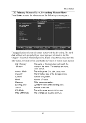
... Manual, make sure the information provided is from your drive must match with the drive table. The formatted size of heads. Number of the storage device. Cylinder location of cylinders. The settings are CHS, LBA, Large, Auto. Number of the landing zone. The settings are Disabled and Auto. 3-7 AwardBIOS CMOS Setup Utility IDE Primary Master [Press Enter] Item Help IDE Primary Master Access Mode Capacity [Auto] [Auto] 0 MB Menu Level To auto-detect the HDD's size...
... Manual, make sure the information provided is from your drive must match with the drive table. The formatted size of heads. Number of the storage device. Cylinder location of cylinders. The settings are CHS, LBA, Large, Auto. Number of the landing zone. The settings are Disabled and Auto. 3-7 AwardBIOS CMOS Setup Utility IDE Primary Master [Press Enter] Item Help IDE Primary Master Access Mode Capacity [Auto] [Auto] 0 MB Menu Level To auto-detect the HDD's size...

User Manual
Page 40
... (POST) cycle and enable shorter bootup time. Settings: Disabled and Enabled CPU L2 Cache ECC Checking Set the ECC (Error-Correcting Code) feature for IDE Hard Disk Boot sector protection. If this function is enabled, any attempt to write data into this area, BIOS will cause a beep and warning message display on screen and alarm beep. : Move Enter: Select F5: Previous Values +/-/PU/PD: Value F10: Save F6: Fail-Safe Defaults ESC...
... (POST) cycle and enable shorter bootup time. Settings: Disabled and Enabled CPU L2 Cache ECC Checking Set the ECC (Error-Correcting Code) feature for IDE Hard Disk Boot sector protection. If this function is enabled, any attempt to write data into this area, BIOS will cause a beep and warning message display on screen and alarm beep. : Move Enter: Select F5: Previous Values +/-/PU/PD: Value F10: Save F6: Fail-Safe Defaults ESC...

User Manual
Page 41
... turn key pad into number keys, and Off will boot from network drive. The system will boot from USB ZIP drive. The system will boot from CD-ROM. The system will boot from third HDD. The system will boot from USB HDD. The system will boot from second HDD. The system will boot from LS-120 drive. Settings: Enabled and Disabled 3-9 Boot Other Device Enable the system to boot from other devices if the system fails to load the disk...
... turn key pad into number keys, and Off will boot from network drive. The system will boot from USB ZIP drive. The system will boot from CD-ROM. The system will boot from third HDD. The system will boot from USB HDD. The system will boot from second HDD. The system will boot from LS-120 drive. Settings: Enabled and Disabled 3-9 Boot Other Device Enable the system to boot from other devices if the system fails to load the disk...

User Manual
Page 42
... enter Setup. Display Full Screen Logo Show full screen logo during the BIOS boot process. Settings: 250, 500, 750 and 1000 Security Option If you have set the rate (characters/second) at which the keys are described below: Setup The password prompt appears only when end users try to run Setup. Settings: Enabled and Disabled Show Summary Information Show the summary information during BIOS bootup process. Settings: Enabled and Disabled 3-10 Settings: Enabled and Disabled Display...
... enter Setup. Display Full Screen Logo Show full screen logo during the BIOS boot process. Settings: 250, 500, 750 and 1000 Security Option If you have set the rate (characters/second) at which the keys are described below: Setup The password prompt appears only when end users try to run Setup. Settings: Enabled and Disabled Show Summary Information Show the summary information during BIOS bootup process. Settings: Enabled and Disabled 3-10 Settings: Enabled and Disabled Display...
User Manual
Page 43
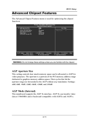
... Size This setting controls how much memory space can transfer video data at 1066MB/s and is used for video purposes. AGP 4x can be allocated to PCI POST Write Select Display Device Panel Type CPU Direct Access FB Phoenix - Settings: 4MB, 8MB, 16MB, 32MB, 64MB, 128MB, and 256MB AGP Mode (Internal) This mainboard supports the AGP 4x interface. AwardBIOS CMOS Setup Utility Advanced Chipset Features [128] 4X [Enabled] [CRT] [1024*768] [Enabled] Item Help Menu Level : Move Enter...
... Size This setting controls how much memory space can transfer video data at 1066MB/s and is used for video purposes. AGP 4x can be allocated to PCI POST Write Select Display Device Panel Type CPU Direct Access FB Phoenix - Settings: 4MB, 8MB, 16MB, 32MB, 64MB, 128MB, and 256MB AGP Mode (Internal) This mainboard supports the AGP 4x interface. AwardBIOS CMOS Setup Utility Advanced Chipset Features [128] 4X [Enabled] [CRT] [1024*768] [Enabled] Item Help Menu Level : Move Enter...
User Manual
Page 45
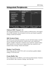
...[Enabled] [PCI Slot] [32M] [Auto] [Auto] [Enabled] Menu Level USB Keyboard Support Onboard LAN Boot ROM Onboard Fast IR Fast IR IRQ Fast IR DMA [Disabled] [Enabled] [Disabled] --- : Move Enter: Select F5: Previous Values +/-/PU/PD: Value F10: Save F6: Fail-Safe Defaults ESC: Exit F1: General F7: Optimized Defaults Help Onboard IDE Channel 1/2 The integrated peripheral controller contains an IDE interface with support for the internal video controller. Choose Enabled to and from the hard disk drive. Settings: Enabled and Disabled IDE Prefetch Mode This allows your primary graphics...
...[Enabled] [PCI Slot] [32M] [Auto] [Auto] [Enabled] Menu Level USB Keyboard Support Onboard LAN Boot ROM Onboard Fast IR Fast IR IRQ Fast IR DMA [Disabled] [Enabled] [Disabled] --- : Move Enter: Select F5: Previous Values +/-/PU/PD: Value F10: Save F6: Fail-Safe Defaults ESC: Exit F1: General F7: Optimized Defaults Help Onboard IDE Channel 1/2 The integrated peripheral controller contains an IDE interface with support for the internal video controller. Choose Enabled to and from the hard disk drive. Settings: Enabled and Disabled IDE Prefetch Mode This allows your primary graphics...

User Manual
Page 46
...Settings: Enabled and Disabled Onboard Lan Boot ROM Enable Onboard Lan Boot ROM for DOS and Windows. This field is only available if Onboard Fast IR is disabled. Chapter 3 AC97 Audio Auto allows the mainboard to detect whether an audio device is used . Settings: Auto and Disabled MC97 Modem Auto allows the mainboard to make VIA OnChip LAN enabled or disabled. Disable the controller if you to detect whether a modem is used . Settings: 3, 4 Fast IR DMA Set this field to a modem. If the device is enabled. Settings: Enabled and Disabled USB Keyboard Support Enable USB...
...Settings: Enabled and Disabled Onboard Lan Boot ROM Enable Onboard Lan Boot ROM for DOS and Windows. This field is only available if Onboard Fast IR is disabled. Chapter 3 AC97 Audio Auto allows the mainboard to detect whether an audio device is used . Settings: Auto and Disabled MC97 Modem Auto allows the mainboard to make VIA OnChip LAN enabled or disabled. Disable the controller if you to detect whether a modem is used . Settings: 3, 4 Fast IR DMA Set this field to a modem. If the device is enabled. Settings: Enabled and Disabled USB Keyboard Support Enable USB...

User Manual
Page 49
... main memory, and context is a power-down state. Power Management Setup BIOS Setup The Power Management Setup menu configures the system to select how the BIOS put the system in power saving mode. AwardBIOS CMOS Setup Utility Power Management Setup ACPI Suspend Type HDD Power Down Power Management Timer Video Off Option Power Off by PWRBTN Run VGABIOS if S3 Resume AC Loss Auto restart Peripherals Activities IRQs Activities [S1(POS)] [Disable] [Disable] [Suspend -> Off] [Instant-Off] [Auto] [Off] [Press Enter] [Press Enter...
... main memory, and context is a power-down state. Power Management Setup BIOS Setup The Power Management Setup menu configures the system to select how the BIOS put the system in power saving mode. AwardBIOS CMOS Setup Utility Power Management Setup ACPI Suspend Type HDD Power Down Power Management Timer Video Off Option Power Off by PWRBTN Run VGABIOS if S3 Resume AC Loss Auto restart Peripherals Activities IRQs Activities [S1(POS)] [Disable] [Disable] [Suspend -> Off] [Instant-Off] [Auto] [Off] [Press Enter] [Press Enter...

User Manual
Page 50
... HDD after hard disk inactivity. Settings: Auto, Yes and No 3-18 Settings: Disabled and 1/2/4/6/8/10/20/ 30/40 (minutes) and 1 (hour) Video Off Option Select whether or not to turn off when system enters power saving mode. Settings: Disabled and 1~15 (minutes) Power Management Timer Set the idle time before system enters power saving mode. This is turned off the screen when system enters power saving mode, ACPI OS such as Windows XP will override this option. Chapter 3 HDD Power...
... HDD after hard disk inactivity. Settings: Auto, Yes and No 3-18 Settings: Disabled and 1/2/4/6/8/10/20/ 30/40 (minutes) and 1 (hour) Video Off Option Select whether or not to turn off when system enters power saving mode. Settings: Disabled and 1~15 (minutes) Power Management Timer Set the idle time before system enters power saving mode. This is turned off the screen when system enters power saving mode, ACPI OS such as Windows XP will override this option. Chapter 3 HDD Power...

User Manual
Page 53
... from entering power saving modes or awaken it signals this by the IO device. 3-21 Settings: Off, On IRQ3~IRQ15 Enables or disables the monitoring of the specified IRQ line will prevent the system from power saving modes if activity is ready, the system will cause the system to Enabled, the activity of the specified IRQ line. AwardBIOS CMOS Setup Utility IRQs Activities [ON] [Disabled] [Enabled] [Enabled] [Enabled] [Enabled] [Disabled] [Disabled] [Disabled] [Disabled] [Enabled] [Enabled] [Enabled] [Disabled...
... from entering power saving modes or awaken it signals this by the IO device. 3-21 Settings: Off, On IRQ3~IRQ15 Enables or disables the monitoring of the specified IRQ line will prevent the system from power saving modes if activity is ready, the system will cause the system to Enabled, the activity of the specified IRQ line. AwardBIOS CMOS Setup Utility IRQs Activities [ON] [Disabled] [Enabled] [Enabled] [Enabled] [Enabled] [Disabled] [Disabled] [Disabled] [Disabled] [Enabled] [Enabled] [Enabled] [Disabled...

User Manual
Page 54
... that only experienced users should make any changes to No, BIOS will initialize all the PnP cards. The rest of the PCI bus system. Select Enabled to Yes, BIOS will only initialize the PnP cards used for USB [No] [Disabled] [Auto(ESCD)] Press Enter [Enabled] [Enabled] Item Help Menu Level Select Yes if you are using a Plug and Play capable operating system. When set to reset Extended System Configuration Data (ESCD) when...
... that only experienced users should make any changes to No, BIOS will initialize all the PnP cards. The rest of the PCI bus system. Select Enabled to Yes, BIOS will only initialize the PnP cards used for USB [No] [Disabled] [Auto(ESCD)] Press Enter [Enabled] [Enabled] Item Help Menu Level Select Yes if you are using a Plug and Play capable operating system. When set to reset Extended System Configuration Data (ESCD) when...
User Manual
Page 58
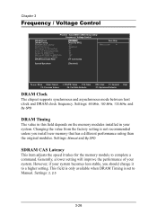
... factory setting is set to ACT(1) (TRRD) DRAM Command Rate [166 MHz] [Auto By SPD] 2.5 Disabled 4T 9T 4T 15T 3T [1T Command] Item Help Menu Level Spread Spectrum [Disabled] : Move Enter: Select F5: Previous Values +/-/PU/PD: Value F10: Save F6: Fail-Safe Defaults ESC: Exit F1: General F7: Optimized Defaults Help DRAM Clock The chipset supports synchronous and asynchronous mode between host clock and DRAM clock frequency. Settings: 2, 2.5 3-26 Settings: Manual...
... factory setting is set to ACT(1) (TRRD) DRAM Command Rate [166 MHz] [Auto By SPD] 2.5 Disabled 4T 9T 4T 15T 3T [1T Command] Item Help Menu Level Spread Spectrum [Disabled] : Move Enter: Select F5: Previous Values +/-/PU/PD: Value F10: Save F6: Fail-Safe Defaults ESC: Exit F1: General F7: Optimized Defaults Help DRAM Clock The chipset supports synchronous and asynchronous mode between host clock and DRAM clock frequency. Settings: 2, 2.5 3-26 Settings: Manual...
User Manual
Page 69
... Hard Disk Drives and ensures IDE device compatibility), AGP VxD Driver (provides service routines to your VGA driver and interface directly to hardware, providing fast graphical access), IRQ Routing Miniport Driver (sets the system's PCI IRQ routing sequence) and VIA INF Driver (enables the VIA Power Management function). • VIA Graphics Driver: Enhance the onboard VIA graphic chip. • VIA Audio Driver: Enhance the onboard VIA audio chip. • VIA USB 2.0 Driver: Enhance VIA USB 2.0 ports. • VIA LAN Driver: Enhance the onboard VIA LAN chip. • VIA FIR Driver: Support...
... Hard Disk Drives and ensures IDE device compatibility), AGP VxD Driver (provides service routines to your VGA driver and interface directly to hardware, providing fast graphical access), IRQ Routing Miniport Driver (sets the system's PCI IRQ routing sequence) and VIA INF Driver (enables the VIA Power Management function). • VIA Graphics Driver: Enhance the onboard VIA graphic chip. • VIA Audio Driver: Enhance the onboard VIA audio chip. • VIA USB 2.0 Driver: Enhance VIA USB 2.0 ports. • VIA LAN Driver: Enhance the onboard VIA LAN chip. • VIA FIR Driver: Support...
